Table of Contents
Advertisement
Quick Links
MULTICORE REMOTE ADAPTER
KA-M790G
Thank you for purchasing this product.
Before beginning to operate this unit, please read
the instruction manual carefully in order to make
sure that the best possible performance is
obtained.
For Customer Use:
Enter below the Serial No. which is located on the
body.
Retain this information for future reference.
Model No.
Serial No.
KA-M790G
INSTRUCTIONS
LST1109-001A
Advertisement
Table of Contents

Related Manuals for JVC KA-M790G


Summary of Contents for JVC KA-M790G
- Page 1 MULTICORE REMOTE ADAPTER KA-M790G INSTRUCTIONS Thank you for purchasing this product. Before beginning to operate this unit, please read the instruction manual carefully in order to make sure that the best possible performance is obtained. For Customer Use: Enter below the Serial No. which is located on the body.
- Page 2 Introduction FOR USA These are general IMPORTANT SAFEGUARDS and certain items may not apply to all appliances. IMPORTANT SAFEGUARDS Read all of these instructions. Save these instructions for later use. All warnings on the product and in the operating instructions should be adhered to. Unplug this appliance system from the wall outlet before cleaning.
-
Page 3: Safety Precautions
Cet appareil numérique de la Class A est conforme à la norme NMB-003 du Canada. CAUTION: CHANGES OR MODIFICATIONS NOT APPROVED BY JVC COULD VOID USER’S AUTHORITY TO WARNING: OPERATE THE EQUIPMENT. TO REDUCE THE RISK OF FIRE OR ELECTRIC... - Page 4 Introduction FOR EUROPE Safety Precautions This equipment is in conformity with the (contiuned) provisions and protection requirements of the corresponding European Directives. This equipment is designed for professional video appliances and can be used in the following NOTE: environments: The rating plate (serial number plate) is on the unit. ●...
- Page 5 Penalties may be applicable for incorrect disposal of this waste, in accordance with national legislation. (Business users) If you wish to dispose of this product, please visit our web page http://www.jvc.eu to obtain information about the take-back of the product. [Other Countries outside the European Union] If you wish to dispose of this product, please do so in accordance with applicable national legislation or other rules in your country for the treatment of old electrical and electronic equipment.
- Page 6 Introduction Safety Precautions (contiuned)
-
Page 8: Table Of Contents
Introduction Contents Introduction Safety Precautions ..... III Contents ......2 Main Features . -
Page 9: Main Features
: Indicates the reference page numbers and reference items. Content of this manual ● All rights reserved by JVC. Unauthorized duplication or reprinting of this manual, in whole or in part, is strictly prohibited. ● All other product names used in this manual are the trademarks or registered trademarks of the respective companies. -
Page 10: Precautions For Proper Use
Introduction Precautions for Proper Use Transportation Do not drop or hit this unit against a hard object when transporting. Moving this unit with the supporting tripod Storage and Usage Locations attached may cause the unit to fall off if they are subject to external impact or vibration. - Page 11 Genlock Signal and System Phase Adjustment When the remote control unit system is used, Genlock signal can either be input from the (GY-HM790CHU/GY-HM790U/GY-HM790CHE/ GY-HM790E) camera or the remote control unit. You can select the device to input the Genlock signal in [Genlock Input] of the [Others] menu on the camera.
-
Page 12: Names Of Parts And Functions
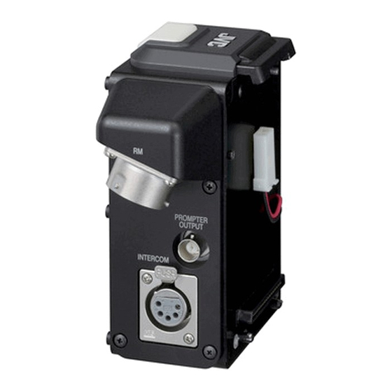
Introduction Names of Parts and Functions [RM] RM Multi-pin Connector (26- [INTERCOM] Intercom Input pin) Terminal (XLR 5 Pin) For connecting to a remote control unit (sold Input terminal for intercom headset. (For separately) using a 26-pin camera cable (sold dynamic microphones only.) separately). - Page 13 If no abnormality is found, press the [BREAKER] button to turn on the power again. If this unit does not function properly after turning on the power, consult our authorized JVC dealers.
-
Page 14: Installation
IA-60a, VL-2PLUS (IDX) [INTERCOM] Terminal [DC INPUT] Terminal Battery Mounting Folder HD Memory Card Camera Recorder GY-HM790CHU/GY-HM790U/GY-HM790CHE*/ Multicore Remote Adapter GY-HM790E* KA-M790G [RM] Terminal [PROMPTER OUTPUT] Terminal Headset DT109 (Beyerdynamic) 26-pin Camera Cable VC-P110 (5 m) VC-P112 (20 m) VC-P113 (50 m) -
Page 15: Attaching This Unit To The Camera
● Do not remove the rubber sheet of the camera. Velcro Fastener ● The plate is only available on IDX Batteries. Battery Mounting Folder Hook Screw A Guide Screw B KA-M790G Screws (x4) Connector A Plate (IDX Battery Rubber Sheet Only) Connectors Connector B... - Page 16 Note: ● Make sure that the connection wires and connectors are properly stored and do not protrude out. Battery Mounting Folder Rubber Sheet (Supplied with this unit) Screw A KA-M790G Screw B (For IDX) Plate (IDX Connectors Battery Only) Storage...
-
Page 17: Remote Control Unit Connection
Remote Control Unit Connection Connecting the Remote Control Unit Connection Connect the [RM] multi-pin connector of this unit to the remote control unit using a 26-pin camera cable. Note: ● Turn off the power of the remote control unit before connecting. Remote Control Unit RM-P210U/E*/RM-HP250AU/RM-HP250DE* Monitor... -
Page 18: Preparations
Remote Control Unit Connection Connecting the Remote Synchronizing with the Camera Control Unit (continued) Select the device to input the Genlock signal You can select the device to input the Genlock Preparations signal in [Genlock Input] of the [Others] menu on the camera. -
Page 19: Using The Tally Function And Call Function
Call signal Using the Tally Function and Call ● Send signal Function The [CALL] button on this unit lights up in red Setting the tally system when pressed. Call signals are sent to the remote control unit To use the tally signal from the remote control while the button is pressed down. -
Page 20: List Of Remote Control Unit Functions
Remote Control Unit Connection : Available Connecting the Remote -: Not available Control Unit (continued) Function RM-HP250AU/ RM-P210U/ RM-HP250DE RM-P210E GAIN VARIABLE List of Remote Control Unit Functions LEVEL : Available WHITE MODE -: Not available Function MANUAL RM-HP250AU/ RM-P210U/ PRESET RM-HP250DE RM-P210E... - Page 21 : Available -: Not available Function RM-HP250AU/ RM-P210U/ RM-HP250DE RM-P210E DETAIL MODE LEVEL V/H BAL DTL FRQ* MIDDLE HIGH AUTO AUTO KNEE KNEE POINT COLOR MATRIX GAMMA MODE LEVEL BLACK ASPECT RATIO MODE LEVEL SMOOTH TRANS LOLUX : Only when [Frame & Bit Rate] on the camera is set to A60B, A24B, or A30B.
-
Page 22: Others
Others Specifications RM multi-pin connector : Composite video signal and Y/PB/PR component video signal output (26-pin) PROMPTER OUTPUT : Prompter video signal output (composite video, BNC) Operating temperature : -5 f to 40 f (Humidity: 80 % and below) range Allowable storage : -20 f to 60 f temperature... - Page 24 2010 Victor Company of Japan, Limited LST1109-001A...