Table of Contents
Troubleshooting

Related Manuals for GreenWorks GPW 1951


Summary of Contents for GreenWorks GPW 1951
- Page 1 1950 PSI / 1.2 GPM ELECTRIC PRESSURE WASHER GPW 1951 OPERATOR’S MANUAL TOLL-FREE HELPLINE: 1-888-90WORKS (888.909.6757) Read all safety rules and instructions carefully before operating this tool. www.greenworkstools.com...
-
Page 2: Table Of Contents
INSTRUCTION Important Safety Instructions………………………………………………………..........3 Specific Safety Rules……………………………………………………………….........4-5 Symbols………………………………………………………………………………........6-7 Electrical………………………………………………………………………………........8 Know Your Pressure Washer…………………………………………………………........9 Packing List..............................10 Assembly………………………………………………………………………………........11-14 Operation………………………………………………………………………………........15-20 Maintenance…………………………………………………………………………........21-22 Troubleshooting……………………………………………………………………….........23-25 Warranty…………………………………………………………………………………….......26 Exploded View…………………………………………………………………………........….27 Parts List……………………………………………………………………………….........28-30 PRODUCT SPECIFICATION Induction Motor……………………………………………………….........120V,60Hz,13Amps Power Cord with In-Line GFCI........................35ft Max. Pounds Per Square Inch Pressure……………………………………........1950psi Rated Gallons Per Minute………………………………………………………........1.2gpm Maximum Inlet Water Temperature……………………………………………..……....104°F(40℃)... -
Page 3: Important Safety Instructions
IMPORTANT SAFETY INSTRUCTIONS W A R N I N G Read and understand all instructions. Failure to follow all instructions listed below may result. in electric W A R N I N G When using this product, basic precautions should always be followed. READ ALL INSTRUCTIONS BEFORE USING THIS PRODUCT children. -
Page 4: Specific Safety Rules
SPECIFIC SAFETY RULES Know your product. Read the operator’s manual carefully. Learn the machine’s applications and To reduce the risk of injury, keep children and visitors away. ep a safe distance from the work area. Use the right product for the job. Don’t force the product or the attachments designed for. - Page 5 SPECIFIC SAFETY RULES W A R N I N G High pressure jets can be dangerous if subject to misuse. Check bolts and nuts for looseness before each use. A loose bolt or nut may cause serious motor problems. Before storing, allow the motor to cool. When servicing use only identical replacement parts.
-
Page 6: Symbols
SYMBOLS Some of the following symbols may be used on this product. Please study them and learn their meaning. Proper interpretation of these symbols will allow you to operate the product better and safer. SYMBOL NAME Volts Voltage Amperes Current Hertz Frequency (cycles per second) Watt... -
Page 7: Symbols
SYMBOLS with this product. SYMBOL SIGNAL MEANING Indicates an imminently hazardous situation, which, if not DANGER Indicates a potentially hazardous situation, which, if not WARNING Indicates a potentially hazardous situation, which, if not CAUTION (Without Safety Alert Symbol) Indicates a situation that may result in property damage. -
Page 8: Electrical
ELECTRICAL ELECTRICAL CONNECTION This product has a precision-built electric motor. It should be connected to a power supply that is 120 If the product does not operate when plugged into an outlet, double check the power supply. DRIP LOOP (See Figure 1.) plug, we recommend using a simple drip loop as shown below. -
Page 9: Know Your Pressure Washer
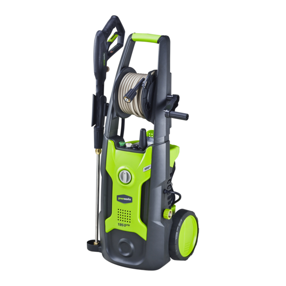
KNOW YOUR PRESSURE WASHER The safe use of this product requires an understanding of the information on the tool and in this familiarize yourself with all operating features and safety rules. (See Figure 2.) Trigger and Wand Assembly Detergent Tank High Pressure Hose Power Cord Storage Tip Storage... -
Page 10: Packing List
PACKING LIST PART NAME ERP NO. FIGURE PART NO. soap tip 40 degree spray tip 25 degree spray tip 31140363 31145363 31208363 Gun Holder 1 341111825 Gun Holder 2 341121825 Spray Tip Cleaning Tool 33201671 388011825 WARNING: ASSEM LING 2 GUN H LDERS Set-up 1950 PSI / 1.2 GPM ELECTRIC PRESSURE WASHER... -
Page 11: Assembly
ASSEMBLY UNPACKING This product requires assembly. packing list are included. W A R N I N G Do not use this product if any parts on the Packing List are already assembled to your product when you unpack it. Parts on this list are not assembled to the product by the manufacturer and require customer Inspect the product carefully to make sure no breakage or damage occurred during shipping. - Page 12 ASSEMBLY ASSEMBLING THE GUN HOLDER (See Figure 3-4.) Insert the gun holder into the gun holders slot until it locks into place. Gun Holder 1 Gun Holder Slot Fig. 3 Gun Holder 2 Gun Holder Slot Fig. 4 EN - 12...
- Page 13 ASSEMBLY CONNECTING HIGH PRESSURE HOSE TO TRIGGER HANDLE (See Figure 5.) 1. Align the pressure hose with the trigger handle and push up and into position. 2. With hose pushed into position on the trigger handle, secure in place by turning the hose lock clockwise until fully tightened.
- Page 14 ASSEMBLY CONNECTING THE GARDEN HOSE (See Figure 7.) C A U T I O N : NOTE:There must be a minimum of 10 feet of unrestricted garden hose between the water intake and the garden hose faucet or shut off valve (such as a “Y” shut off connector). Run water through the hose for 30 seconds to clean any debris from the hose.
-
Page 15: Operation
OPERATION W A R N I N G Do not allow familiarity with the product to make you careless. Remember that a careless fraction of a W A R N I N G Always wear eye protection with side shields marked to comply with ANSI Z87.1. Failure to do so could W A R N I N G Do not use any attachments or accessories not recommended by the manufacturer of this product. - Page 16 OPERATION To add detergent: Place pressure washer upright on a flat surface Pour detergent into tank Reinstall cap Detergent Use Black Soap Tip Only Fig. 8-1 Fig. 8-2 C A U T I O N : acids. To use: Connect low pressure black soap spray tip to the wand connector. (See Figure 8-2.) Squeeze the trigger and the detergent will automatically be mixed with the water and dispensed from the spray tip.
- Page 17 OPERATION STARTING AND STOPPING THE PRESSURE WASHER (See Figure 9.) C A U T I O N : Do not run the pump without the water supply connected and turned on. Connect the garden hose. Turn the garden hose on then squeeze the trigger and run water hose with motor in OFF position until a steady stream of water appears.
- Page 18 OPERATION USING THE SPRAY TIPS (See Figure 10.) spray tip for your application. Turn off the pressure washer and shut off the water supply. Pull trigger to release water pressure. Engage the lock-out on the trigger handle by pushing the trigger lock button to the right. Pull out the desired spray tip from the tip storage on the handle.
- Page 19 OPERATION W A R N I N G NEVER change spray tips without engaging the lock-out on the trigger handle and NEVER point the TO DISCONNECT A SPRAY TIP FROM THE SPRAY WAND ONCE THE CLEANING JOB IS COMPLETE: Turn off the pressure washer and shut off the water supply. Pull trigger to release water pressure. spray tip in the tip storage area on the units folding handle.
- Page 20 OPERATION OPERATING THE PRESSURE WASHER (See Figure 12.) Use only detergents designed for pressure washers. Many detergents may requrie mixing prior to use. Prepare cleaning solution as instructed on the solution bottle. Fig. 12 To clean: Pour detergent in the detergent tank. Install the black soap tip on the spray wand.
-
Page 21: Maintenance
MAINTENANCE W A R N I N G cause product damage. W A R N I N G to release water pressure and disconnect the high pressure hose. Failure to follow these instructions GENERAL MAINTENANCE oil, grease, etc. W A R N I N G Do not at any time let brake fluids, gasoline, petroleum based products, penetrating oils, etc.,come in contact with plastic parts. - Page 22 MAINTENANCE QUICK WINTERIZING PROCEDURE If you cannot do the Optimum Winterizing procedure, you can still protect your pressure washer from winter damage by doing below: Disconnect all water connections. Turn on the machine for a few second, until the remaining water in the pump exits. Turn off immediately. Do not allow high-pressure hose to become kinked.
-
Page 23: Troubleshooting
TROUBLESHOOTING PROBLEM POSSIBLE CAUSE SOLUTION Turn switch to the “ON” ( | ) position. “OFF” (O) position. Power cord is not Plug in power cord. plugged in. Electrical outlet does not supply adequate Try a different outlet. Motor will not start. power. - Page 24 TROUBLESHOOTING PROBLEM POSSIBLE CAUSE SOLUTION Detergent is too thick. Dilute detergent. Filter on detergent suction tube is clogged. Detergent is not coming Damaged or clogged out. detergent suction suction tube. tube. Spray tip is obstructed. Loose connection. Tighten connection. Garden hose connection leaks.
-
Page 25: Troubleshooting
TROUBLESHOOTING PROBLEM POSSIBLE CAUSE SOLUTION Verify that only the pressure washer is running minimum. on this circuit. System has residual Turn unit “OFF”, squeeze trigger on spray pressure. wand to release pressure, then turn unit "ON". Voltage loss due to Unplug any extension cords attached and plug Motor buzzes but fails to extension cord. -
Page 26: Warranty
GREENWORKS™ hereby warranties this product, to the original purchaser with proof of purchase, for a period of one (1) years against defects in materials, parts or workmanship. GREENWORKS™, at its own the instructions in the owners’ manual supplied with the product from new. -
Page 27: Exploded View
EXPLODED VIEW EN - 27... -
Page 28: Parts List
PARTS LIST ITEM NO. PART NO. DESCRIPTION 341091639 Switch knob 341071825 Front panel 341111630 Performance label panel 341111825 Gun holder 1 31208363 Turbo nozzle 31225363 25 degree nozzle 31240363 40 degree nozzle 34139319 Soap nozzle(black) 34211319 Nozzle grommet 341011825 Front housing 341021633 341031633 Wire box seal... - Page 29 PARTS LIST ITEM NO. PART NO. DESCRIPTION 36499363-1 Power cord 36401661 Capacitor 34222302 3410801 Power cord clip 3320303 Screw ST3.5*16-F 341141639 Inlet connector 1 34223302 Power cord seal 34900363 Inlet tube 33911302 Tube clamp 34116365 Inlet connector 2 34216302A O-ring 12*2 33307671 U-clip 311051825...
-
Page 30: Parts List
PARTS LIST ITEM NO. PART NO. DESCRIPTION 342011626 Soap tank cap 33201671 Cleaning tool 31140363 Metal gun handle assy 31145363 Metal wand assy 34145363-2 Hose reel handle 34144363-2 Hose reel axle 33203363 34143363-2 Hose reel axle 32211316A Screw ST3.5*12 341131825 Right hose reel 31141363 Rubber high pressure hose assy 1... - Page 31 TOLL-FREE HELPLINE: 1-888-90WORKS (888.909.6757)
Need help?
Do you have a question about the GPW 1951 and is the answer not in the manual?
Questions and answers