
Related Manuals for Hydro-Gear ZT-5400 Powertrain


Summary of Contents for Hydro-Gear ZT-5400 Powertrain
- Page 1 Hydro Gear Parts or New Units Call 606-678-9623 or 606-561-4983 ZT-5400 Powertrain™ Service and Repair Manual BLN-0014 August 2010 www.mymowerparts.com...
- Page 2 Hydro Gear Parts or New Units Call 606-678-9623 or 606-561-4983 www.mymowerparts.com...
-
Page 3: Table Of Contents
Troubleshooting . . . . . . . . . . . . . . . . . . . . . . . . . . . . . .8 ZT-5400 Powertrain Exploded View . . . . . . . . . 38-39 Service and Maintenance . -
Page 4: Foreword
H e a d q u a r t e r e d i n S u l l i v a n , I l l i n o i s , Internal repair procedures require that the Hydro-Gear is a world leader in the design, transaxle unit be removed from the vehicle . -
Page 5: Description And Operation
Km/h) without starting the engine. General desCrIpTIOn The ZT-5400 Powertrain utilizes an internal in- The ZT-5400 Powertrain is a self contained unit line floating disc brake controlled by a “cam” designed for the transfer and control of power . style actuating arm . -
Page 6: Hydraulic Schematic
. The oil supply for the hydraulic system During the operation of the transaxle, fluid of the ZT-5400 Powertrain ™ is also utilized for is “lost” from the hydraulic loop through leak lubricating the components of the final drive paths designed into the product for lubrication assembly . -
Page 7: External Features
Hydro Gear Parts or New Units Call 606-678-9623 or 606-561-4983 eXTernal feaTures ZT-5400 pOwerTraIn ™ TWO SPEED ARM (OPTIONAL) INPUT SHAFT BRAKE ARM EXPANSION TANK PORT OIL COOLER PORT (OPTIONAL) FILTER CAP BYPASS ACTUATOR — Inboard View— OIL FILL VENT PORT CHARGE PUMP —... - Page 8 Hydro Gear Parts or New Units Call 606-678-9623 or 606-561-4983 eXTernal feaTures ZT-5400 pOwerTraIn ™ EXPANSION TANK PORT/FILL PORT OIL FILL VENT PORT — Top View— INPUT SHAFT INPUT SHAFT CONTROL ARM Control arm return to neutral — Outboard View—...
-
Page 9: Technical Specifications
5 Bolt Flange parking brake Type Internal Disc weight of unit 55 lb (24 .9) kg prOduCT IdenTIfICaTIOn The model and configuration of the ZT-5400 Powertrain can be determined from the label shown below . HYDRO-GEAR 1015-1001R 1015-1001R Assembled in USA... -
Page 10: Safety
Keep the work area neat and orderly . Be sure ZT-5400 powertrain ™ transaxle, fully it is well lit, that extra tools are put away, trash read and understand the safety precau- and refuse are in the proper containers, and dirt tions described in this section. -
Page 11: Troubleshooting
Disengage Brake, Replace Broken or Missing Brake Return Spring Tr a n sa x le l e a ks oil Damaged seals, housing, or gaskets Replace damaged components Air trapped in hydraulic system Purge hydraulic system, Page 11 ZT-5400 Powertrain www.mymowerparts.com... -
Page 12: Service And Maintenance
. 6 . Inspect the vehicle control linkage to the directional control arm on transaxle . Also, Fill the ZT-5400 Powertrain to the top of the oil insure the control arm is securely fastened fill port. to the trunnion arm of the transaxle . -
Page 13: Fluid Change Procedure
Note: The oil volume figure shown does not ing . include what is in the expansion tank 3. Install a new filter (Hydro-Gear part number line or the expansion tank. That will 71943). Install a new O-ring onto the filter have to be determined by the OEM/end cover and install the filter cover. See Figure user due to varying line sizes/lengths 3a. -
Page 14: Purging Procedures
. complete . Before starting, make sure the transaxle/trans- mission is at the proper oil level. If it is not, fill to the specifications outlined on page 9. ZT-5400 Powertrain www.mymowerparts.com... -
Page 15: Return To Neutral Setting
(bypass disengaged) . Raise the vehicle’s drive tires off the ground to allow free rotation . NOTE: It may be necessary to remove the drive tire from the axle hub to access the linkage control and the transaxle return arm. 2 . Remove the Original Equipment Manufac- turer’s (OEM’s) control linkage at the control arm . figure 4, return to neutral ZT-5400 Powertrain www.mymowerparts.com... -
Page 16: 2-Speed Option Settings
2-speed lock down arm (165) with the THE DISASSEMBLY OF THIS UNIT. 2-speed control arm (168) against the stop . 6 . Stop the engine and reconnect any OEM linkage . figure 5, 2-speed Control arm figure 6, Transaxle Control arm ZT-5400 Powertrain www.mymowerparts.com... -
Page 17: Tear Down And Reassembly
IMPORTANT: When internal repair is performed pages 38 and 39 . on the ZT-5400 Powertrain ™ , the filter assem- bly must be replaced . Many of the parts and subassemblies of this... -
Page 18: Tools
Oil Fill Vent Port Plug, Metal 200-280 in-lbs [22 .5-31 .6 Nm] Exspansion Tank Port Plug Metal 180-240 in-lbs [20 .33-27 .11 Nm] External Cooler Port Plug Nut, HEX, 1/2-20 W/ PATCH 360-520 in-lbs [40 .6- 58 .7Nm] * If a 275 ft-lbs torque wrench is not available please use the alternative torque procedure outlined on page 36. ZT-5400 Powertrain www.mymowerparts.com... -
Page 19: Transaxle Removal
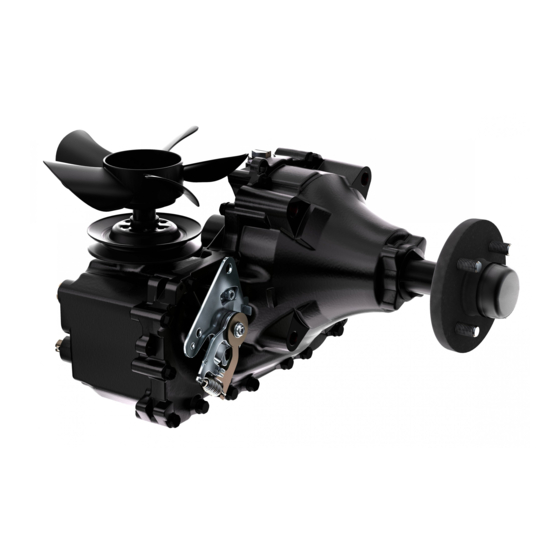
Do not disassemble the unit any far- performing the repair procedures pre- ther than necessary to accomplish the sented in this section. required repairs. Before starting any disassembly, make Reassembly is accomplished by per- certain that your work area is neat and forming the “Assembly” portions of the clean. Clean the external parts of the procedures. If the unit has been com- transaxle. pletely disassembled, a summary of The following procedures are pre- the assembly procedures, in the order sented in the order recommended for a in which they should occur, is given on page 33. figure 7, ZT-5400 powertrain Transaxle ZT-5400 Powertrain www.mymowerparts.com... -
Page 20: Fan And Pulley
2 . When tightening the castle nut (113)*, refer to the table on page 15 for the required torque values . NOTE: As a general rule, use the low end of the torque specification on fasteners when reassembling the unit. *SEE PAGE 36 FOR ALTERNATE TORQUE METHOD. figure 8, fan and Hub ZT-5400 Powertrain www.mymowerparts.com... -
Page 21: Return To Neutral Assembly Option
5 . Remove the neutral arm (59) and the spacer when reassembling the unit. (58) . NOTE: Only remove the seal (51) and the RTN control arm stroke limiter (65) if dam- aged or worn. Mark the orientation of the stroke limiter before removal. Inspection 1 . Inspect all parts for excessive wear or dam- age . Replace if necessary . figure 9 return To neutral ZT-5400 Powertrain www.mymowerparts.com... -
Page 22: Control Arm Assembly
NOTE: Only remove the lip seal (51) and stop plate (65) if damaged or worn, or if doing a complete disassembly. Mark the orientation of the stop plate before removal. Inspection 1 . Inspect all parts for excessive wear or dam- age . Replace if necessary . figure 10, Control arm ZT-5400 Powertrain www.mymowerparts.com... -
Page 23: Filter And Filter Cover
15 . Inspection 1 . Inspect all parts for wear or damage . Re- place as necessary . 2. Check for old filter grommet stuck on the filter tube. Remove if present. figure 11, filter and filter Cover ZT-5400 Powertrain www.mymowerparts.com... -
Page 24: Brake Assembly
4 . Remove the brake handle (130) and the bushing (128) . 5 . Remove the seal (127) and discard . NOTE: Only remove the seal (127) if damaged or worn, or if doing a complete disas- sembly. Inspection 1 . Inspect all parts for wear or damage . Re- place as necessary . figure 12, brake assembly ZT-5400 Powertrain www.mymowerparts.com... -
Page 25: 2-Speed Arm
5 . Remove the seal (164) and discard . 4 . Install the 2-speed actuating arm (168) . screw (167) . NOTE: Only remove the seal (164) if damaged or worn, or if doing a complete disas- 5 . Install the new external retaining ring sembly. (169) . figure 13, 2- speed arm ZT-5400 Powertrain www.mymowerparts.com... -
Page 26: Bypass Actuator
1 . Inspect the actuator bypass rod (43) for wear or damage . Replace if necessary . NOTE: Take care to insure that the actuator bypass rod is free of burrs that may cut the rubber lip seal. 2 . Inspect the housing bore . figure 14, bypass actuator ZT-5400 Powertrain www.mymowerparts.com... -
Page 27: Side Housing
Refer to the screw tightening pattern on Replace if necessary . page 35 . 5 . When tightening the fasteners, refer to the table on page 15 for the required torque values . figure 15, side Housing ZT-5400 Powertrain www.mymowerparts.com... -
Page 28: Axle Shaft And Planetary Gear Set
(95), planet gears (96), sun gear (97) and the carrier (98) . figure 17, planetary Gear set Inspection 1 . Inspect all items of the planetary gear set NOTE: When installing the ring gear assembly for wear and or damage . — line up the ring gear tabs with the housing tabs. figure 16, planetary Gear set ZT-5400 Powertrain www.mymowerparts.com... -
Page 29: Charge Pump And Oil Tube
6 . Remove and discard the O-ring (146) housing when it is installed . Inspection 1 . Inspect items of the charge cover assem- bly for wear and or damage . Replace if necessary . figure 18, Charge pump ZT-5400 Powertrain www.mymowerparts.com... -
Page 30: Input Shaft
(70) . Inspection 1 . Inspect the bearing and input shaft for wear or damage . Inspect the splines on the shaft for possible damage . Replace if neces- sary . figure 19, Input shaft ZT-5400 Powertrain www.mymowerparts.com... -
Page 31: Swashplate
. Replace the pump block assembly if necessary . 3 . Inspect for scratches on the machined sur- faces of the swashplate (50) . figure 21, pump block assembly PUMP BLOCK ASSEMBLY figure 20, swashplate ZT-5400 Powertrain www.mymowerparts.com... -
Page 32: Center Section
. Inspection 1 . Inspect for surface wear damage(scartches or scoring) on the machined surfaces of the center section (20) . MOTOR BLOCK ASSEMBLY MOTOR SHAFT (90) CENTER SECTION ASSEMBLY figure 22, Center section ZT-5400 Powertrain www.mymowerparts.com... -
Page 33: Brake Assembly And Motor Shaft
4 . Remove the brake shaft nut (126) and washer (125) . 5 . Remove the brake shaft (120), the splined cam (121), the puck cam (122) and brake puck (124) . figure 23, brake assembly and motor shaft ZT-5400 Powertrain www.mymowerparts.com... -
Page 34: Motor Cyl Block, 2-Speed Shaft & Swashplate
2 . Apply a light coating of oil to all running surfaces . 3 . Reassemble the items of the motor block assembly . place the thrust bearing as- sembly (80) so the thick race contacts the motor block pistons. figure 24, motor Cylinder block assembly ZT-5400 Powertrain www.mymowerparts.com... -
Page 35: Center Section And Magnet
(36), the spring (35) and the ball (34) . Inspection 1 . Inspect the all items of the charge galley assembly for wear or damage . Replace if necessary . 2 . Clean off the magnet (39) . figure 25, Charge Galley assembly and magnet ZT-5400 Powertrain www.mymowerparts.com... -
Page 36: Assembly After A Complete Teardown
. — OR — 12. Install any removed plugs/fittings into the main housing located above the bypass RTN assembly installation: Install the spacer bore . (58), neutral arm (59), washer (60) and ZT-5400 Powertrain www.mymowerparts.com... -
Page 37: Assembly After A Complete Teardown
(110) into the keyway on the axle . Slide the hub (111) onto the axle and secure with the castle nut (113) . 20 . Perform the purge procedures listed on page 11 . NOTE: Prior to applying the new sealant, the figure 26, sealant application diagram ZT-5400 Powertrain www.mymowerparts.com... -
Page 38: Screw Tightening Sequence
Starting with the number “1” screw location, tighten sequentially through to “17.” Torque each screw to 230 – 290 lb-in (25 .9 – 32 .7 Nm) . NOTE: As a general rule, use the low end of the torque specification. From Opposite Direction figure 27, screw tightening sequence ZT-5400 Powertrain www.mymowerparts.com... -
Page 39: Alternate Castle Nut Torque Method
. Install cotter pin . 10 . Reinstall nut cover . Placement mark Placement mark figure 29 figure 28 figure 28 / figure 29, alternate Torque method ZT-5400 Powertrain www.mymowerparts.com... - Page 40 Hydro Gear Parts or New Units Call 606-678-9623 or 606-561-4983 ZT-5400 Powertrain www.mymowerparts.com...
-
Page 41: Zt-5400 Powertrain Exploded View
Hydro Gear Parts or New Units Call 606-678-9623 or 606-561-4983 ZT-5400 pOwerTraIn™ eXplOded VIew ZT-5400 Powertrain www.mymowerparts.com... - Page 42 Gear, Planet, 23T Fan, 9 .0 (5 Blade, Cw) Gear, Sun, 22T Washer, Od Slotted, 53 X 1 .63 X .06 Carrier Nut, Hex, 1/2-20 W/ Patch Ball, Thrust, .75 Washer Ring, Retaining, 1 .25 Kit, RTN ZT-5400 Powertrain www.mymowerparts.com...
-
Page 43: Glossary Of Terms
Hydrostatic Transaxle: A multi component assembly including a gear case and a hydrostati- transmission . Hydrostatic Transmission: The combination of a hydraulic pump and motor in one housing to form a device for the control and transfer of power . Inlet Line: A supply line to the pump . ZT-5400 Powertrain www.mymowerparts.com... - Page 44 Valve: A device which controls fluid flow direction, pressure, or flow rate. Variable Displacement Pump: A pump in which the displacement per revolution can be var- ied . Volumetric Displacement: The volume for one revolution . ZT-5400 Powertrain www.mymowerparts.com...
-
Page 45: Notes
Hydro Gear Parts or New Units Call 606-678-9623 or 606-561-4983 nOTes ZT-5400 Powertrain www.mymowerparts.com... - Page 46 Hydro Gear Parts or New Units Call 606-678-9623 or 606-561-4983 nOTes ZT-5400 Powertrain www.mymowerparts.com...
- Page 47 Hydro Gear Parts or New Units Call 606-678-9623 or 606-561-4983 www.mymowerparts.com...
- Page 48 Hydro Gear Parts or New Units Call 606-678-9623 or 606-561-4983 © 2010 HYDRO-GEAR Printed in U.S.A. Rev. P9 www.mymowerparts.com...
Need help?
Do you have a question about the ZT-5400 Powertrain and is the answer not in the manual?
Questions and answers