Table of Contents

Related Manuals for Quintum Tenor DX

Summary of Contents for Quintum Tenor DX
- Page 1 Tenor DX ® VoIP MultiPath/Gateway Switch Tenor and Quintum are registered trademarks. PacketSaver, Quintum Technologies, Inc., Risk Free VoP, VoIP Made Easy, TASQ, SelectNet, and SelectNet Technology are trademarks of Quintum Technologies, Inc.
-
Page 2: Table Of Contents
What is the Tenor DX? ........ - Page 3 What is a CDR? ............6-3 Establish connection between Tenor DX and CDR Server ......6-4...
- Page 4 Change CDR Password ..........6-5 Tenor DX Establishes Connection with CDR Server ......6-6 CDR Server Establishes Connection with Tenor DX .
-
Page 5: About This Guide
bout this Guide P/N 480-0049-00-13 Preface-1... -
Page 6: What's Included
Chapter 2: Hardware Components. Hardware description, including the front and rear panels, as well as LEDs and required cables. • Chapter 3: Installation. Describes how to install the Tenor DX unit, including how to connect, power up and assign the IP address. •... -
Page 7: Typographical Conventions
About this Guide Typographical Conventions Product Guide Conventions Certain typographical conventions are used throughout this product guide. See below. • All commands you enter via keystrokes appear in bold (e.g., Press Enter or Press Ctrl-I). • All text commands you enter via Telnet session or command line typing appear in italics (e.g., type active). -
Page 8: Finding Help
About this Guide Finding Help Refer to the Product Guide for help. The Table of Contents and Index tells you where to find information eas- ily. Extensive configuration help is available via the Tenor Configuraton Manager and Tenor Monitor online help systems or the Command Line Interface online help system. -
Page 9: Chapter 1: Overview
1: Overview This chapter gives you a general overview of the Tenor DX including feature descriptions and capa- bilities. Specifically, the following topics are covered: Tenor DX A description of Features Capabilities Call Routing/Management Options H.323 Gatekeeper Services P/N 480-0049-00-13... -
Page 10: What Is The Tenor Dx
Chapter 1: Overview What is the Tenor DX? The Tenor DX is a high-density VoIP (Voice over Internet Protocol) H.323/SIP switch that converts voice, fax, and modem data on digital circuit switched trunks, and transmits it over the IP network. - Page 11 Your network stays as is, and the call type is transparent to the user. This technology boasts superior voice quality without compromising reliability. The Tenor DX is available in the versions listed in Table 2-1. Table 2-1 Tenor DX MultiPath Switch configurations Tenor Digital DX...
-
Page 12: Features
Tenor DX will switch the call to the PSTN automatically and transparently. The Tenor continu- ously monitors your data network for jitter, latency and packet loss, and transparently switches cus- tomer calls to the PSTN when required. -
Page 13: Packetsaver™ Reduces Bandwidth Consumption
Chapter 1: Overview PacketSaver™ reduces bandwidth consumption PacketSaver packet multiplexing technology reduces the amount of IP bandwidth required to sup- port multiple calls flowing between two endpoints. PacketSaver minimizes bandwidth usage by aggregating samples from multiple VoIP conversations and packing them into a larger IP packet with a single IP header. -
Page 14: Capabilities
Virtual Tie Line Tenor DX can emulate a tie trunk. It provides all of the functionality of a tie trunk, including the con- siderable cost savings, but eliminates the need for a PBX trunk to be configured, or marked as a tie trunk. -
Page 15: Nataccess
Chapter 1: Overview NATAccess™ NATAccess is an intelligent network address translation technology. It enables VoIP networks with multiple H.323 endpoints to operate behind firewalls equipped with H.323 Network Address Trans- lation (NAT); this provides maximum network security. NATAccess simplifies deployment by elim- inating the need to place the Tenor on a public IP network. -
Page 16: Call Routing/Management Options
VoIP call, a Line Circuit, or trunk typically for connection to a termination device on the user’s premises such as a PBX. The routing decision made by the Tenor DX is based upon your configuration and the dialed number. - Page 17 (IP Network) Ethernet Intra-trunk Routing - “Hairpinning”. As a result of intra-trunk routing, incoming calls from a particular Trunk Circuit are switched by Tenor DX to be routed back out the same trunk circuit rout- ing group. Figure 1-5 Intra-Trunk Routing...
-
Page 18: Routing Table Options
Static Routes. Static Routes are used between networks and other H.323 devices that are not regis- tered to the network through the Border Element (such as non-Quintum gateways). A static route associates endpoints (as represented by their IP address) with Directory Number patterns. -
Page 19: Call Management Features
PBX. Trunk Group Support. The Tenor DX supports trunk groups, which are groups of T1 or E1 chan- nels used to connect the Tenor to other carriers (such as local telephone company) or to PBX equip- ment used for circuit aggregation. -
Page 20: H.323 Gatekeeper Services
Gateways, IP phones, and H.323 terminals. The Gatekeeper communicates with other Gatekeepers through a Border Element. When using a group of Tenor DX units, you can assign one unit as the Gatekeeper for the network. We recommend you configure each as its own gatekeeper. -
Page 21: Call Services
In addition, if you are using more than one Tenor unit, you can configure one of the border elements for that zone. The Tenor DX unit can use two border elements: primary and secondary. These work together as one entity to provide redundancy and fault tolerance; there are no hierarchal differences. - Page 22 Chapter 1: Overview Admissions Control. All H.323 endpoints must register and request permission to enter the gate- keeper’s zone; the gatekeeper will confirm or deny access to the network. The gatekeeper authorizes network access and protects the integrity of the network using Admissions Request (ARQ), Admis- sions Confirmation (ACF) and Admissions Reject (ARJ) messages.
-
Page 23: Sip User Agent
Chapter 1: Overview SIP User Agent SIP (Session Initiation Protocol) is a signaling protocol used to establish a session on an IP network for voice control and management; it is a request-response protocol that closely resembles Hypertext Transfer Protocol (HTTP), which forms the basis of the World Wide Web. SIP re-uses many of the constructs and concepts of Internet protocols such as HTTP and Simple Mail Transfer Protocol (SMTP). -
Page 24: Chapter 2: Hardware Components
hapter 2: Hardware Components This chapter tells you what is contained in your hardware package. A description of each component is also included. Specifically, the following topics are covered: Hardware Description Cables P/N 480-0049-00-13... -
Page 25: Hardware Description
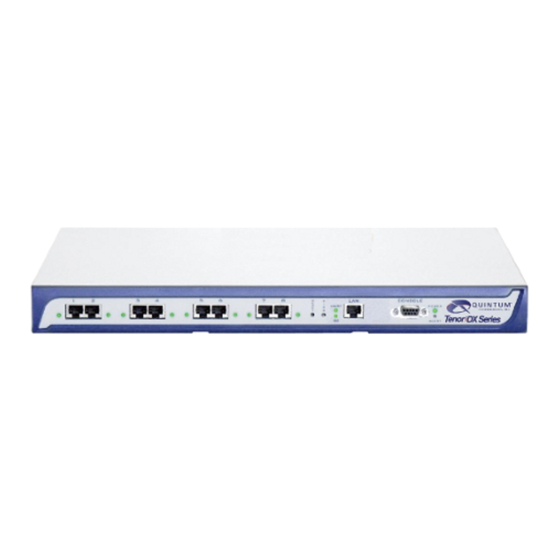
Chapter 2: Hardware Components Hardware Description The Tenor DX is a stackable/rack mountable device which provides PSTN and PBX connections (through T1/ E1/PRI lines), as well as connections to the Ethernet LAN and a PC. The unit provides eight RJ-45 ports in which you can connect to a PBX or the PSTN. - Page 26 Chapter 2: Hardware Components Figure 2-2 10/100 BASE-T Ethernet Port Pin Order Table 2-1 Input/Output 10/100 Ethernet port Pin # Signal Definition Color TX + Transmit Data White w/orange TX - Transmit Data Orange RX + Receive Data White w/green RSVD Reserved Blue...
- Page 27 Chapter 2: Hardware Components Pin # Function Description N.C. No Connect N.C. No Connect N.C. No Connect P/N 480-0049-00-13...
-
Page 28: Front Panel Leds
Off: Activity is being transmitted at 10 Mbps. Power Power Green On: Indicates power is on. Off: Power is off. Alert Alert Amber Operational Status. Off: Tenor DX is working prop- erly. On: One or more diagnostic tests have failed. P/N 480-0049-00-13... -
Page 29: Back Panel
Chapter 2: Hardware Components Back Panel AC Receptacle Power Switch Ground Screw Label • AC Receptacle. Receptacle in which to plug in a power cord; the other end will plug into an AC outlet for power. • Power Switch. Switch to turn power on and off. •... -
Page 30: Rj-45 Cables
Chapter 2: Hardware Components Cables The cables listed in Table 2-4 are required to connect a Tenor DX to various interfaces. Contact Quintum for ordering information, if necessary. NOTE: A crossover cable is required when connecting to a Line side (PBX) interface (when supplied by Quintum, this is a red RJ-45 cable). - Page 31 Chapter 2: Hardware Components RJ-45 Ethernet Cable (10/100) An RJ-45 (10/100BaseT) straight through shielded cable is used to connect Tenor DX to an Ethernet LAN. Cable pinouts are listed in Table 2-5. Color specifications are applicable to the RJ-45 cable provided.
- Page 32 RJ-45 to RJ-45 Straight Cable (T1/E1/PRI WAN to Trunk Side) An RJ-45 (T1/E1) straight cable is used to connect Tenor DX T1/E1 (1-8) port to the Trunk Side (PSTN). Cable pinouts are provided below. If this cable is provided by Quintum, the color is green. The color specifica- tions are applicable to the RJ-45 straight cable provided.
- Page 33 RJ-45 to RJ-45 Crossover Cable (T1/E1/PRI WAN to PBX) An RJ-45 (T1/E1) crossover cable is used to connect Tenor DX T1/E1 (1-8) port to the Line Side (PBX). Cable pinouts are provided below. If this cable is provided by Quintum, the color is red. The color specifica- tions are applicable to the RJ-45 crossover cable provided.
-
Page 34: Db-9 Serial Rs-232 Cable
The Serial RS-232 9-pin cable with a DB-9 male connector (with RS-232 interface) is used to connect the Tenor DX to your PC’s asynchronous serial port. The pin order for DB-9 male and female connectors are shown in Figure 2-9 and Figure 2-10. -
Page 35: Chapter 3: Installation
3: Installation This chapter gives you installation instructions, as well as how to position the Tenor DX successfully within your network. Specifically, the following topics are covered: Installation Connection Install Ground Safety Cable Power up the System Assign IP Address... -
Page 36: Pre-Installation Guidelines
Ensure no equipment is put on top of the chassis. Inspect Package Contents Before you install the hardware, ensure the following components are included in your shipment: • Tenor Tenor DX and Mounting Hardware • 1 AC Power Cable •... -
Page 37: Rack Install
1. Choose a position for the chassis within the rack. WARNING: If the Tenor DX unit is the only equipment installed in the rack, ensure it is level with the rack to avoid the rack from becoming unbalanced. Mount as low as possible to avoid a high center of gravity. - Page 38 Chapter 3: Installation Figure 3-1 Rack Installation (Front View) Tenor DX Rack Mounting Holes Wall Mount There are two mounting brackets available to mount the unit to the wall. Pre-installation Guidelines • Ensure the wall is level and stable. •...
- Page 39 Chapter 3: Installation Attach the unit to the wall as follows: 1. Determine the wall area to mount the unit. With chalk or a soft pencil, mark the install area according to Figure 3-2. NOTE: Ensure the unit is level. Figure 3-2 Wall Mounting Dimensions 3/16”...
-
Page 40: Connection
The instructions which follow tell you how to connect an RJ-45 cable (included in your package) between one of the eight network ports on the Tenor DX and a PBX. See Chapter 2: Hardware Components for a list of RJ- 45 cable pinouts you can use to make a custom cable. -
Page 41: Connect To Trunk Interface - Pstn
1. Plug one end of the straight through RJ-45 cable into one of the eight network ports on the front of the unit. The cable from Quintum would be the green RJ-45 cable. See Chapter 2: Hardware Components for cable pinouts if you are making your own cables, or if you wish to attach the table to a punch down block. -
Page 42: Connect To Ethernet Lan
You can use these instructions for general connection purposes only. The Ethernet hub/switch manufacturer’s documentation should provide specific instructions for connection to another device, such as the Tenor DX. Only LAN 1 is available for use; LAN 2 is reserved for future use. -
Page 43: Connect To Pc Console
Connect to PC Console You will need to connect the Tenor DX to your workstation’s serial port via RS-232 connection. (This connec- tion will be used when you assign an IP address to the unit.) For the instructions below, it is assumed you are connecting to a Windows PC. -
Page 44: Install Ground Safety Cable (If Required)
Install Ground Safety Cable (if required) The Tenor DX provides an Earth Ground screw (a #6 screw). This screw provides earth ground to the unit if the AC power receptacle you are plugging into does not contain a ground prong (the Quintum supplied power cable has a three prong connector). -
Page 45: Power Up The System
Chapter 3: Installation Power up the System Once you have all cables connected properly, you are ready to turn the system on as follows: 1. Plug in the power cord to an AC outlet. 2. Locate the on/off switch on the back of the unit and click the switch to On. The unit will power up and the LEDs will flash and turn off;... -
Page 46: Assign Ip Address
Assign IP Address Before you can configure a Tenor DX, you need to assign a valid IP address. When a Tenor DX is shipped to a customer, you need to assign a valid IP address for each unit. An IP address is a 32 bit (up to 12 numeric char- acters) address used to identify each network device in the TCP/IP network. -
Page 47: Change Ip Address
2. Click on Start> Programs> Accessories> Communications>HyperTerminal> Run. The Connection Description window will be displayed. 3. Enter a connection name (i.e., name for each unit such as Tenor DX New Jersey). 4. Click Ok. 5. Choose the serial port on your PC from the Connect Using drop down list box (i.e., Direct to Com 1). Click Ok. - Page 48 IP address, Subnet Mask and Default Gate- way. 14. At the Quintum prompt, type ei to reach the Ethernet prompt and then type config to change to the Con- figuration mode. 15. To set the IP address, type set ipa followed by the IP address.
-
Page 49: Load Software Upgrade
Chapter 3: Installation Load Software Upgrade To upgrade the software, download the upgrade from the CD ROM you received with the unit, or download the latest software/documentation from www.quintum.com. P/N 480-0049-00-13 3-15... - Page 50 4: Getting Started: Tenor Configu- ration Manager/Tenor Monitor This chapter tells you how to get started configuring and monitoring the Tenor DX through the Tenor Config- uration Manager and the Tenor Monitor. Overview Tenor Configuration Manager Tenor Monitor P/N 480-0049-00-13...
-
Page 51: Chapter 4: Getting Started: Tenor Configuration Manager/Tenor Monitor
Quintum products, including the Tenor DX. The software was designed to run on any PC; you simply designate the IP address for the Tenor product (i.e., Tenor DX) on which you would like to configure or perform monitoring functions. -
Page 52: Tenor Configuration Manager
Chapter 4: Getting Started: Tenor Configuration Man- Tenor Configuration Manager The Tenor Configuration Manager is used to configure all aspects of the Tenor DX, including system, Ether- net, CDR, signaling, circuit, and VoIP configuration. Through the Configuration Manager, you are able to configure all aspects of the Tenor unit. -
Page 53: Tenor Monitor
1. Access the Tenor Monitor icon (located in the area in which you specified during installation. For example, click on Start > Programs >Quintum Tenor Monitor>Tenor Monitor. The Tenor Monitor will open up. The User Name and Password window will be displayed. - Page 54 hapter 5: Getting Started: Command Line Interface (CLI) This chapter tells you how to use access and use the CLI. Specifically, the following topics are included: CLI Description Access CLI Configuration via CLI P/N 480-0049-00-13...
-
Page 55: Chapter 5: Getting Started: Command Line Interface (Cli)
Through the CLI, there are also commands you execute to simplify the process of configuring and monitoring the Tenor DX unit. Some of these commands are globally used, others are specific to the mode in which you are working. For example, the set command, available globally from within the Configuration mode, enables you to set attributes for different options. -
Page 56: User Login Ids
Once the Tenor DX has been initially configured with an IP address network and is connected, the easiest way to connect to the Tenor DX and use the CLI is through a standard Telnet session from any PC on your IP net- work. -
Page 57: Serial Port Connection
Serial Port Connection When the Tenor DX is first shipped to you, you must connect to the unit using this method to assign an IP address. Once this is assigned, you can use the CLI to reach the serial port of the Tenor. A null-modem cable must be used to connect to the CLI using this port, if you are directly connected to the unit. -
Page 58: Configuration Via Cli
Chapter 5: Getting Started: Command Line Interface Configuration via CLI Once you are connected to the Command Line Interface, you can configure the system, as well as perform diagnostics and monitor system information. For specific information, see the Online Help you received with the CD. -
Page 59: Chapter 6: Call Detail Recording
hapter 6: Call Detail Recording This chapter tells you how to display and understand the Call Detail Recording (CDR) feature. Examples are included later. Specifically, the following topics are included. Overview CDR Description Establish Connection CDR Output P/N 480-0049-00-13... -
Page 60: Overview
Chapter 6: Call Detail Recording Overview There are two ways to view CDRs for the Tenor DX unit: through the Command Line Interface (CLI) or through Tenor Monitor. The information for accessing CDRs via CLI is detailed in this chapter: see the Tenor Configuration Manager/ Tenor Monitor User’s Guide for information about viewing alarms via Tenor Monitor. -
Page 61: What Is A Cdr
A CDR file can be created each day to collect CDRs from each Tenor DX that connects to the server. From this information you can capture billing type data which can be used by separate software components to cre- ate billing reports, view call records, and generate daily/weekly/monthly statistics reports. -
Page 62: Establish Connection Between Tenor Dx And Cdr Server
In order to capture CDRs, a connection between the Tenor DX unit and the CDR server must be established. A Tenor DX can be configured to connect up to two CDR servers via port 9002, 9003, 9004, and 9005. Based on configuration, the Tenor DX unit can either establish a TCP/IP session with one or all of these CDR servers. -
Page 63: Configure Tenor Dx For Connection To Cdr Server
Once you configure this information, you will be able to capture CDR reports through the CDR server and the Tenor DX unit, it will be able to establish a TCP/IP session with the server on its own. Setup CDR Server and assign password Before the CDR server can collect CDRs, you must install the cdrserver.cfg file as follows:... -
Page 64: Tenor Dx Establishes Connection With Cdr Server
IP address and unit name of the Tenor DX. The CDR server will then supply the sequence num- ber of the last CDR that it has received from the Tenor DX unit. If the last CDR number is unknown, the server should send 0 for the sequence number. -
Page 65: Cdr Output
1 again. If the system has a problem and loses connectivity, the CDR server can send the Tenor DX unit the last Call ID that is received. The Tenor DX unit will reply with all records that con- tain a Call ID which is greater than the one last received. - Page 66 Resource Unavailable, Unspecified. This cause is used to report a resource unavailable event only when no other cause applies. Local IP Address: The IP address for the Tenor DX unit originating the CDR. The entry will be in the follow- ing format: xxx.xxx.xxx.xxx.
- Page 67 Chapter 6: Call Detail Recording Remote IP Address: IP address for the remote destination Tenor DX. This will be generated only if the call is VoIP; if the call is circuit based, this field will be blank. The entry will be in the following format: xxx.xxx.xxx.xxx.
-
Page 68: Sample Record For Extended Tenor Dx Cdr Format 3, 4, 103, 104
1 again. If the system has a problem and loses connectivity, the CDR server can send the Tenor DX unit the last Call ID that it received. The Tenor DX unit will reply with all records that con- tain a Call ID which is greater than the one last received. - Page 69 Resource Unavailable, Unspecified. This code is used to report a resource unavailable event only when no other code applies. Local IP Address: The IP address for the Tenor DX unit originating the CDR. The entry will be in the follow- ing format: xxx.xxx.xxx.xxx.
- Page 70 PIN Code. PIN code entered. 14 digits maximum. This field will be blank if a PIN code is not configured. Local Call ID #. Unique identification number, generated by the local-side Tenor DX, for call record matching purposes. Generated only for IP calls.
-
Page 71: Chapter 7: System Alarms
hapter 7: System Alarms This chapter tells you how to use the Alarm Manager to view and understand alarms generated by the system. Specifically, the following topics are included: Overview Monitor Alarms View Alarms P/N 480-0049-00-13... -
Page 72: Overview
Chapter 7: System Alarms Overview There are two ways to view alarms for the Tenor DX unit: through the Command Line Interface (CLI) or through Tenor Monitor. The information for accessing alarms via CLI is detailed in this chapter: see the Tenor Configuration Man- ager/Tenor Monitor User’s Guide for information about viewing alarms via Tenor Monitor. - Page 73 Chapter 7: System Alarms Field Definition Valid Entry Severity Level or alarm severity. 1 = Critical (complete system is affected). 2 = Major (major problem is detected). 3 = Minor (minor problem is detected). 4 = Info (Information about a minor problem).
-
Page 74: Valid Alarms
Loss of Framing (Red Alarm) Signal is not being transmitted; there is no layer 1 syn- chronization. Critical Remote Alarm indication (Yellow Tenor DX is receiving a yellow alarm signal from the Alarm) network. Critical Loss of signal A loss of signal (32 consecutive zeros) at least once dur- ing a 1 second period. - Page 75 Chapter 7: System Alarms Severity Alarm Description (appears as Definition part of severity (text appears in desc field) field) Critical IVR Configuration Missing Appears if an attempt to make an IVR call has been made when a valid IP address is not configured. Occurs if an IVR call has been passed through acci- dently, without a real intention to use IVR for subse- quent calls, while both of the servers were disabled.
- Page 76 Chapter 7: System Alarms Severity Alarm Description (appears as Definition part of severity (text appears in desc field) field) Minor Hardware component failed A hardware component has failed. Check all compo- nents, hardware connections, etc. Minor Log RADIUS server error Displayed when the RADIUS server fails to send required data or the data sent by the RADIUS server has improper values.
-
Page 77: View Alarms
Chapter 7: System Alarms View Alarms The Command Line Interface (CLI) enables you to view alarms through the Monitor mode. You can view active alarms, as well as view an alarm history list. You are now ready to view active alarms and an alarm history, or both. See the sections which follow: Display all Alarms You are able to display both active alarms and an alarm history as follows: 1. -
Page 78: Display Alarm History
Chapter 7: System Alarms Display Alarm History 1. Through CLI, access the Monitor prompt. 2. Type alarm h. An alarm history will be displayed. See section How to Read Alarms for field definitions. If you enter alarm without a command following it, both active alarms and the alarm history will be dis- played. -
Page 79: Chapter 8: Diagnostics/Maintenance
8: Diagnostics/Maintenance This chapter tells you how to troubleshoot Tenor DX operation, as well as how to maintain the health of your system. You will find information about how to view the unit’s LEDs, as well as how to interpret the chassis’... -
Page 80: Before You Begin
Chapter 8: Diagnostics/Maintenance Before you Begin Before you begin troubleshooting a potential malfunction, it is a good idea to check your basic hardware con- nections. See below. • Ensure power cord is firmly installed in the back panel’s power jack and the other end is plugged into the AC power source. -
Page 81: Diagnostics
Network issues may cause a number of problems. Contact the Central Office to perform test procedures. Communication with Command Line Inter- The IP address of the Tenor DX unit may be incorrect. face (CLI) cannot be established using Tel- net. -
Page 82: Verify Unit Provisioning
Verify Unit Provisioning An error with Tenor DX‘s provisioning may cause a number of problems. It may be a simple error, such as an incorrect IP address or telephone number, or it may be something more complex, such as incorrect T1/E1 parameters. -
Page 83: Monitoring
Monitoring Alarms Alarms help you identify where a specific problem is occurring with the Tenor DX unit. Through the CLI, you can review alarms via Command Line Interface (CLI). Verify all severity 1 alarms first; these alarms indicate that the unit is in critical condition and the entire system is affected. -
Page 84: Change Unit Date And Time
Chapter 8: Diagnostics/Maintenance Change Unit Date and Time You can change the unit’s date and time via Command Line Interface (CLI) as follows: 1. Access the CLI through a Telnet session. See Chapter 5: Getting Started: Command Line Interface (CLI) for more information. -
Page 85: If You Need Additional Help
If you suspect the problem to be on the network end, contact your Central Office to verify proper operation. After completing all troubleshooting/maintenance procedures and reviewing the Common Symptoms/Prob- lems section, you can contact the Customer Service Department at the following: Quintum Technologies, Inc. 71 James Way Eatontown, NJ 07724... - Page 86 ppendix A: Specifications/Approvals P/N 480-0049-00-13...
- Page 87 T1 - 100 Ohms balanced Jack: RJ48C (Cable to trunk side interference, RJ-45 straight through twisted pair. A green cable provided by Quintum). RJ48C (Cable to line side interface, RJ-45 crossover twisted pair. A red cable provided by Quintum). P/N 480-0049-00-13...
- Page 88 Appendix A: Specifications/Approvals LAN Connection LAN Support: 10/100 Mbps Ethernet Connection Type: Full Duplex/Half Duplex Physical Position: 19” (48.7 cm) rack mountable or wall-mountable Depth: 10 3/4” (27.6 cm) Width 17 3/8” (44.5 cm) Height: 1 3/4 ” (4.5 cm) Weight 7.2 lbs (3.24 kg) Electrical...
- Page 89 Appendix A: Specifications/Approvals Agency Approvals FCC Part 15, Class A ICES-003 AS/NZS 354:95 EN55022:98 Class A EN55024:98 EN61000-3-2:95 EN61000-3-3:95 TELECOM FCC Part 68 CS-03 TS016 TS038 TBR4 ISDN Layer4 SAFETY UL/cUL 60950 EN60950:92 TS001 P/N 480-0049-00-13...
- Page 90 Appendix A: Specifications/Approvals FCC WARNINGS This equipment has been tested and found to comply with the limits for Class A digital device, pursuant to Part 15 of the FCC Rules. These limits are designed to provide reasonable protection against harmful interfer- ence in a residential installation.
- Page 91 In the event of device malfunction, all repairs should be performed by Quintum Technologies, Inc. or an authorized agent. It is the responsibility of users requiring service to report the need for service to Quintum Technologies or to one of our authorized agents. In the event service is required, refer to the Technical Support insert for information.
- Page 92 Appendix A: Specifications/Approvals Canadian Notice The Industry Canada label identifies certified equipment. This certification means that the equipment meets certain telecommunications network protective, operation, and safety requirements. The Department does not guarantee the equipment will operate to the users' satisfaction. Before installing this equipment, users should ensure that it is permissible to be connected to the facilities of the local Telecommunications Company.
- Page 93 Appendix A: Specifications/Approvals EU Directive on Disposal of Waste Electrical and Electronic Equip- ment (WEEE) This equipment is classified as Type 3 IT and Telecommunications Equipment under the terms of EU Directives 2002/96/EC and 2003/108/EC. These directives are now being transposed into law by the individual EU member states.
-
Page 94: Declaration Of Conformity
Eatontown NJ Type of Equipment: Digital VoIP Gateway Model Number: Tenor DX Series, Call Relay 60 We, the undersigned, hereby declare that the equipment specified above conforms to the above Directive(s) and standard(s) as of this date. Place: Eatontown, NJ, USA Date: 9/15/05 Karl V. - Page 95 INDEX overview access via serial port access via Telnet configuration configuration options About this guide description Alarms modes definition config 5-2 display via CLI diagnostic 5-2 field definitions maintenance 5-2 list of monitor 5-2 monitor navigation user login IDs Configuration Back panel getting started AC receptacle...
- Page 96 Tenor Configuration Manager required materials Tenor DX VoIP MultiPath Switch wall mount capabilities description product types What is Tenor DX MultiPath Switch LEDs Tenor Monitor front panel getting started monitor Troubleshoot common problems general maintenance Maintenance...
- Page 97 10 to 100 Mbps. Border Element. Provides access into or out of an admin- Ethernet port. A port on the Tenor DX which provides istrative domain. The Tenor DX has two types of Bor- RJ-45 jacks for connection to a 10/100 Ethernet LAN der Elements: Primary and Secondary.
- Page 98 Los Angeles. When these sites connect together over the data network or the public network, it is consid- RJ-45. A CAT 5 cable used to connect the Tenor DX to ered a WAN. As a result, intra-corporate information an Ethernet, Line Circuit or Trunk Circuit.
- Page 99 Zone. A group of endpoints (e.g, gateways, terminals, etc.) in one corporate site. P/N 480-0049-00-13 Glossary-3...
- Page 100 Customers are responsible for shipping and insurance charges to return the defective product. Quintum shall pay for shipping and insurance charges for the part being sent to the customer.
- Page 101 PLEASE NOTE: All shipments require an authorized RMA number. If the Customer does not comply with this procedure as set out above, Quintum reserves the right to charge Customer for the cost of the replace- ment Product and/or freight (including duties and taxes) from Quintum regardless of the reason for the return. Quintum also reserves the right to invoice the Customer for a replacement Product at the same time as the replacement is cross-shipped.
Need help?
Do you have a question about the Tenor DX and is the answer not in the manual?
Questions and answers