Table of Contents
Advertisement
Advertisement
Table of Contents

Related Manuals for Leica MX400


Summary of Contents for Leica MX400
- Page 1 MX400 GPS Navigator Operator’s Manual M A D E T O M E A S U R E...
-
Page 2: Product Information
Operator’s Manual DGPS Navigator Version 3.3 MX400 Series GPS MX400 MX400B MX412 MX412B MX412BR Product Information The model and serial number of your instrument are given on the instrument. Enter the model and serial number in the spaces provided below. Always refer to this information when you contact your dealer. -
Page 3: Symbols Used In This Manual
Symbols Used In This Manual Danger Indicates an imminently hazardous situation which, if not avoided, will result in death or serious injury. Warning Indicates a potentially hazardous situation which, if not avoided, could result in death or serious injury. Caution Indicates a potentially hazardous situation which, if not avoided, may result in minor or moderate injury and/or appreciable material, financial and envirtonmental damage. -
Page 4: Scope Of This Manual
Scope Of This Manual This manual reflects the software capabilities in version 3.2 software. We have attempted to take care and develop manuals which provide in-depth information. Where possible, we have attempted not only to describe what you see on the screen, but how to understand or use it as well. -
Page 5: How To Contact Us
Unlike many other consumer electronics industries which only sell consumer electronic devices, your marine dealer is often your best advisor for installation and service of your new GPS receiver. Leica strongly encourages you to utilize the knowledge and experience of your sales and service dealer. -
Page 6: Table Of Contents
Table of Contents Operator’s Manual Table of Contents Product Information ................ i Product Information ................ i Symbols Used In This Manual ............ii Symbols Used In This Manual ............ii Scope Of This Manual ..............iii Related Documents ............... iii Scope Of This Manual ..............iii Related Documents ............... - Page 7 Operator’s Manual Table of Contents Keypad & Display Description........... 10 Differential GPS Traffic Light Operation: ........11 Red Flashing ................11 Red/Yellow Solid ................ 11 Red Solid ................... 11 Yellow/Green Solid ..............11 Yellow Solid ................12 Green Solid ................12 GPS Traffic Light Operation: ............
- Page 8 Table of Contents Operator’s Manual Navigate ................... 20 Dead Reckoning ................21 NAV1 - The Panorama Screen ............22 NAV2 - Basic Steering Information ..........24 NAV 3 - Expanded Navigation Information ........26 NAV4 - Sensor Input Navigation ............ 27 Route ..................
- Page 9 Operator’s Manual Table of Contents Removing Waypoints..............60 Moving waypoints ................61 Downloading Waypoints & Routes To Other Devices ....63 Rnn - Routes: ................63 RTE - Active Route: ..............64 WPL - Waypoint Location - NMEA 0183 Standard: ....65 WPL - Waypoint With Symbols &...
- Page 10 Table of Contents Operator’s Manual Auxiliary ..................92 AUX1 - Alarm Log ..............92 AUX2 - Speed Graph ..............93 AUX3 - Fuel Information .............. 93 AUX4 - Sun Almanac ..............94 AUX5 - Moon Phases ..............94 AUX6 - Batteries ................94 AUX7 -Unit Information ...............
- Page 11 Operator’s Manual Table of Contents Configuration ................113 Alarms ..................113 Anchor - Anchor Watch Alarm ............. 114 COG SOG - Course & Speed Filter Settings & Setup ....114 Compass - External Compass Input & Magnetic Variation Table ..............115 Datum - Current Position Calculation ..........
- Page 12 Table of Contents Operator’s Manual Security ..................149 Set & Drift ..................149 SJB - Smart Junction Box Control ..........150 Time - Mode And Format Control ..........152 Wind .................... 153 Wpt & Rte Input - Uploading Waypoints Into the receiver ... 154 Appendix A - Datum List ............
- Page 13 Operator’s Manual Table of Contents viii Version 3.3...
-
Page 14: About Gps Navigation
DGPS navigator, and a communication link to transmit the pseudorange corrections. Leica has pioneered the development of the DGPS Beacon System. This system allows the user to benefit from the accuracy of DGPS... -
Page 15: Special Notes
Operator’s Manual About GPS Navigation receiving equipment, and navigators). Marine radio beacons operating in the 283.5 to 325.0 KHz fre- quency range are in widespread use for direction finding in coastal navigation. Because the beacon system has been in place and widely used for many years, it provides an effective means for the transmission of DGPS signals. -
Page 16: Charts And Navigational Aids
About GPS Navigation Operator’s Manual wave length bands. Charts and Navigational Aids Positions obtained from charts are not always as accurate as your navigator (due to environmental changes, the dates of charts, and datum offsets if the datum differs from the one in use by the navigator). -
Page 17: Functional Description
Operator’s Manual Functional Description Functional Description Receiver Configurations This GPS receiver is available in six basic configurations, identified by product description and part number. Refer to the Auxiliary Unit Information section of the manual to view sample screens to identify your particular model. 6 Channel GPS The basic 6 channel GPS navigator is capable of receiving DGPS corrections in the RTCM SC-104 version 2 format via one of the... -
Page 18: 12 Channel Gps With Built-In Beacon
Functional Description Operator’s Manual ports. However, it does not have an internal marine beacon DGPS receiver. This model is supplied with a GPS only Volute, Discus, or Globe style antenna. Should you decide at a later date to upgrade your 6 channel to a 12 channel receiver or your 12 channel receiver to a 12 channel with built-in beacon, the display unit must be returned to the factory to install the appropriate components and software. -
Page 19: 12 Channel Dual Control Integrity Monitor
Operator’s Manual Functional Description as a slave unit) and one 12 channel with built-in beacon (operating as a master unit) with one GPS and Loop (H-Field) combined Discus style antenna. It is capable of receiving DGPS corrections in the RTCM SC-104 version 2 format via one of the four input data ports, or via its internal marine beacon DGPS receiver. - Page 20 Functional Description Operator’s Manual differences detailed in the GPS, DGPS, & CFG sections of the manual. Note: In general, this manual will refer to all versions of this product line simply as the receiver, navigator, or GPS. Where distinction between models is necessary, the particular model type will be called out.
-
Page 21: Dgps Beacon System
Operator’s Manual Functional Description DGPS Beacon System As Maritime Safety Administrations, Navy, and Coast Guard Organizations realize the limitations of standard GPS positioning, many have begun installing DGPS Beacon Stations. While an understanding of this system is not necessary for operating receiv- ers with internal beacon receivers, you may want to read on to have a better understanding of how your receiver is capable of achieving the high levels of accuracy made possible by this network of... - Page 22 Keypad & Display Description Operator’s Manual Because of the limited range of the beacon transmitters, typically 150 to 400km, the corrections generated by the reference station are always valid for users who can receive the correction signals and maintain a 5 meter or better accuracy figure. Just like the satellite segment which maintains in-orbit spare satellites, most beacon stations operate two live running GPS reference stations.
-
Page 23: Keypad & Display Description
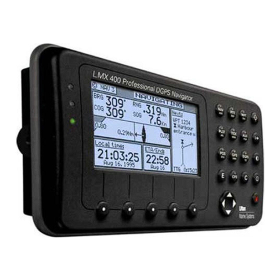
Operator’s Manual Keypad & Display Description Keypad & Display Description Traffic Display Function Keys Lights RT E N AV PLOT T I D E A U X PO S GP S DGPS 6289-01A.400 Softkeys Cursor Key Refer to the illustration above. The Traffic Lights on the left side of the display will tell you how your navigator is operating. -
Page 24: Red Flashing
Keypad & Display Description Operator’s Manual Red Flashing not tracking satellites (no position update). This is normally for the first 2 minutes or so when turning the unit on. The very first time you turn the unit on, or if the memory is reset or lost, this condition is also normal. -
Page 25: Green Solid
Operator’s Manual Keypad & Display Description from time to time during normal operation. It usually occurs when you are tracking 3, 4, or 5 satellites, and the satellites have poor geometry relative to your position. If you are patient, the condition will normally go back to Green Solid, when you pick up another satellite, or the geometry of the existing satellites improves. -
Page 26: Red Solid
Keypad & Display Description Operator’s Manual available, this LED sequence is provided to quickly identify the DR navigation mode. A DR indicator is also displayed on all screens in the upper left hand corner of the display Red Solid tracking one or more satellites (no position update). This is also normal for the first 2 minutes or so when turning the unit on. -
Page 27: The Softkeys
Operator’s Manual Keypad & Display Description The receiver uses a Transflective LCD display screen. It provides optimum viewing in virtually all lighting conditions. To change the display contrast or backlight condition, select the CFG function key and scroll down to the Lighting menu choice. Refer to the CFG section of the manual for a complete description of menu options. -
Page 28: Mark Position
Keypad & Display Description Operator’s Manual the power on/off key. The ten function keys with alpha abbreviations on them are described in the ensuing chapters. The eight function keys with symbols are described below. The function keys are also used in the edit mode to enter alpha- numeric information into screen data fields. -
Page 29: Power On/Off
Operator’s Manual Keypad & Display Description Configuration section of the manual for a complete description of the Lighting menu options. POWER ON/OFF This function key turns the unit on and off. When depressed while the unit is on, you will be prompted to select a YES or NO softkey to confirm your action. -
Page 30: E E (Edit)
Keypad & Display Description Operator’s Manual Ø Navigation data output on the NMEA ports (i.e. BWC and BWR), are changed to reflect the current crisis situation. This way, other interfaced equipment can also help guide you back to the MOB position. When the MOB condition is canceled via a MOB screen softkey, the NMEA sentences will automatically revert to the active route information. -
Page 31: C C (Clear)
Operator’s Manual Keypad & Display Description for some reason that you don’t want to use the changes you have made, and you can’t quite remember what the original information was, pressing the Escape softkey will restore the original informa- tion. However, once you press the E key, all changes are accepted and the original data is lost. - Page 32 Keypad & Display Description Operator’s Manual depressions on the function key (when not in the edit mode) allow you to page through all of the screens available for that particular function. You can accomplish the same thing by selecting a function and using the left and right arrows on the cursor key (which is sometimes faster).
-
Page 33: Navigate
Operator’s Manual Navigate Navigate There are four basic NAV screens. NAV4 only provides data if appropriate sensors (i.e. wind speed/direction logs, NMEA com- pass, etc.) are interfaced and activated on the receiver. The NAV functions are highly interactive with the RTE1 screen, and a number of CFG menu selections. -
Page 34: Dead Reckoning
Navigate Operator’s Manual Ø Position - sets 2D or 3D mode, antenna height, Lat/Lon, Loran or Decca TDs, or UTM, and some alarm limits. There is an optional software package available (on most models, refer to the Options Manual) to setup a user grid as well. The option is explained in the Position, and CFG Position sections of this manual Ø... -
Page 35: Nav1 - The Panorama Screen
Operator’s Manual Navigate upper left portion of the screen. NAV1 - The Panorama Screen This screen is designed to give you a unique 3 dimensional look at the active route you are to follow. We typically refer to it as a runway view, because you can see navigation markers, your course line, the cross-track error lines, and waypoint flags as you pass them. - Page 36 Navigate Operator’s Manual water (LOG). The distance value displayed as the Range (RNG) is calculated from your present position to the waypoint. Time To Go (TTG) is the calculated time it will take you to reach the waypoint, based on your Waypoint Closure Velocity (see NAV4 description). To keep the screen from jumping around when you are stopped, the screen freezes the graphic representation when your speed is under 0.5 Kn in DGPS mode or 2.0 Kn in GPS mode.
-
Page 37: Nav2 - Basic Steering Information
Operator’s Manual Navigate graphic screen. If you drift outside of your cross-track error limit and you decide not to return to your original course line, you can reset your course line from your present position to the waypoint by selecting Reset XTE from the display. - Page 38 Navigate Operator’s Manual In the bottom half of the window, the vertical line in the center represents your course line. The checkered area on the left and right side of this area represents the out of bounds or beyond the cross- track error limit area.
-
Page 39: Nav 3 - Expanded Navigation Information
Operator’s Manual Navigate work hard to get you back on course. Press the E key again to get back into normal display mode. In addition, if you decide you want to skip this waypoint, and go on to the next one, Press the E key, and the Skip Waypoint softkey one time. -
Page 40: Nav4 - Sensor Input Navigation
Navigate Operator’s Manual You will find the right hand window to be a nice tool. In addition to identifying the waypoint you are currently approaching, it identifies the waypoint at the end of the next leg as well. But the really unique feature of this screen is the graphical representation of your actual course line approach angle relative to the next leg of your course. - Page 41 Operator’s Manual Navigate Log - Sets the input port number, sensor type (pulse or NMEA 0183), sensor offset, alarms, and a correction factor (if needed). Set & Drift - Sets the mode to manual or automatic (derived from GPS). Sets the time-out before applying calculated values. GPS calculated values are used prior to the time-out period.
- Page 42 Navigate Operator’s Manual your course and speed. You will find the Course Over Ground (COG, which is calculated by GPS), Heading (HDG, which is your NMEA 0183 compass input), and Heading To Steer (HTS) data on the left side of the window. HTS data is calculated by considering your Heading , minus COG and adding BRG to the waypoint.
- Page 43 Operator’s Manual Navigate Velocity Made Good: Next Present Beginning Position Waypoint Waypoint SOG 13 Kn Effect of Distance to Set & Drift Waypoint Travelled Original Course Line Waypoint Closure Velocity: Present Next Beginning Position Waypoint Waypoint SOG 13 Kn WCV 9 Kn Effect of Set &...
-
Page 44: Route
Route Operator’s Manual Route There are two RTE screens. The NAV functions are highly interactive with the RTE1 screen. The RTE2 screen allows you to create a pool of predetermined routes that you might use often, so you need only create the route one time. Routes are created from waypoints. -
Page 45: Rte1 - The Active Route
Operator’s Manual Route (refer to Creating a Multi-Waypoint Active Route section of this manual). When you are finished using the copied route in RTE1, you can erase the route from the RTE1 screen and the original stored route will remain intact in the RTE2 screen. The following CFG1 menus directly impact the RTE functions: Ø... -
Page 46: Creating A Route Using The Goto Key
Route Operator’s Manual You can enter waypoints using different datums into the route The RTE1 screen is where you are likely to do most of your trip preparation. There are several methods you can use to create routes, you are sure to find one or more methods which meet your needs in the sections which follow. - Page 47 Operator’s Manual Route Choose In Bank - allows you to scroll through the Waypoint Bank. Align the cursor with the desired waypoint and press the E key. The waypoint is automatically inserted in to the active route and the unit will revert to the NAV screens, displaying bearing and distance to this waypoint.
- Page 48 Route Operator’s Manual If you make a mistake, you can use the cursor key to position the cursor over the mistake and over write the error. Use the 9 key to insert a space in the description, if needed. Use the 0 key to select a special character, if needed. International characters are available by selecting the associated function key.
-
Page 49: Erasing An Existing Route
Operator’s Manual Route approaching. Keep in mind that these are the fixed calculated values between these two coordinates and not the real time changing values that you will see in the navigate screens between your present position and your next waypoint during normal navigation. Below Waypoint 0 is the waypoint you defined in the GOTO function. -
Page 50: Creating A Multi-Waypoint Active Route
Route Operator’s Manual The active route is now empty and ready for new input. If you want to work in other areas of the receiver first, you will need to press the E key to exit the edit mode. Creating A Multi-Waypoint Active Route There are four methods to create a multi-waypoint route: Ø... -
Page 51: Insert By Number
Operator’s Manual Route damage (i.e. erase waypoints in the Waypoint Bank, or routes in the Route Bank), so have some fun and find out how helpful this GPS receiver really is. You might want to skip the examples which follow and jump ahead to the Maneuvering Within The Route section later in this section to understand some of the more advanced features of the software, if you are already comfortable with setting up a basic route. -
Page 52: Choose In Bank
Route Operator’s Manual When you have found the waypoint you want, press the Insert This WPT softkey. You can then choose to select another waypoint using the same method, select Escape to go back one level and use another method to enter waypoints, or select Done to go back to the main menu. -
Page 53: Insert New Waypoint
Operator’s Manual Route 6. When you have found the waypoint you want, press the Insert This WPT softkey. 7. When you are finished, press the Done softkey to get back to the main menu. 8. You can then choose to select another waypoint using the same method, select Escape to go back one level and use another method to enter waypoints, or select Done do go back to the main menu. -
Page 54: Insert Route
Route Operator’s Manual 5. Choose either Bearing Distance or Lat/Lon (Grid Point, or TD if you are using other coordinate systems). Use the keypad to type in the range and bearing from the previous waypoint (or present position in the case of the first waypoint) or the coordinates you want and their appropriate description. -
Page 55: Maneuvering Within The Route
Operator’s Manual Route 5. Use the cursor key to scroll through the available defined routes, which are created in the RTE 2 screen, in numerical order. 6. When you have found the route you want, press the Insert Fwd or the Insert Reverse softkey. Insert Fwd enters the route from the top of the defined list into the active route. -
Page 56: Inserting Waypoints Or Routes Into An Existing Route
Route Operator’s Manual The easiest way to accomplish either of these tasks, is to scroll through the route with the cursor key until the cursor arrow is at the bottom of the last waypoint you want designated as passed (that is, white characters on a black background), whether this waypoint was passed several waypoints ago, or is yet to be passed. - Page 57 Operator’s Manual Route Then press the E key. 4. Use one or more of the insert methods described in the Creating A Multi-Waypoint Active Route section above. This example shows Waypoint 7 inserted into the route, using the Insert By Number method: Press the E key to end editing.
- Page 58 Route Operator’s Manual 3. Use the cursor key to move the magnifying glass icon over the waypoint or marker that you want to go to. Verify that the waypoint number and coordinates are correct in the left hand window. Press the GOTO function key. Press the E key to exit the edit mode.
-
Page 59: Reversing The Active Route
Operator’s Manual Route Reversing The Active Route Once you get to your final destination, you might want to follow the same route home. To quickly accomplish this, simply use the Reverse Direct. softkey from the main RTE1 menu. 1. Select the RTE key until the RTE1 screen is displayed. 2. -
Page 60: Eta Setup
Route Operator’s Manual ETA Setup If you choose to use this function, it is probably better to operate the unit in UTC time mode if you are going to cross one or more time zones. Note that the time entered uses the offset to UTC applied in the CFG1 Time display. -
Page 61: Sog Based On Arrival Date & Time
Operator’s Manual Route SOG Based on Arrival Date & Time: Enter the arrival time and date. Be sure to enter the date as day, month, year, as indicated on the screen. Press the Done softkey. In this mode, the actual SOG is compared to the required SOG to meet the specified arrival date and time. -
Page 62: Rte2 - The Route Bank
Route Operator’s Manual RTE2 - The Route Bank The Route Bank is a convenient place for you to preprogram segments of a long voyage, or to program routes that you follow over and over again. Creating routes for the Route Bank uses the same methods as the Active Route with a few exceptions: you can’t use the GOTO key, and you can’t use the Plotter screen. - Page 63 Operator’s Manual Route Press the Done softkey when you are finished editing the name. Note: It is a good idea at this point to select Lock Route so that way you won’t accidentally erase the route sometime in the future. Finally press the E key to exit the edit mode.
-
Page 64: Waypoint
Waypoint Operator’s Manual Waypoint The Waypoint Bank (WPT) is a single list of up to 2000 waypoints that you store for use in the routes you create. It also stores special coordinates and time for you, through the use of the Mark or Event function key or external input, or the MOB function key or external input. -
Page 65: Creating And Editing Waypoints
Operator’s Manual Waypoint Search For WPT - allows you to type a symbol, or name and the screen displays all waypoints having the exact match of the name you type. If you are unsure of the complete name, type a few of the characters you know are in the name, and the software will display all waypoints having the corresponding characters. - Page 66 Waypoint Operator’s Manual 3 Make New WPT 4a Use WGS-84 Datum 4b Use Datum Other 4c Create a new WPT Based Than WGS-84 on a Range & Bearing Se l ect Lat/Lon (W84) from an existing WPT Select Lat/Lon Datum Select Range Bearing Select desired datum Enter desired range...
- Page 67 Operator’s Manual Waypoint Lat/Lon (W84) - allows you to enter coordinates in the WGS 84 datum. This choice takes you directly into the coordinate input screen. Go to step 5. Lat/Lon Datum - allows you to choose a datum (see the list in the screen sample above) from the more than 110 available Datums.
- Page 68 Waypoint Operator’s Manual press Change to choose from the more than 110 available Datums. Highlight the desired datum and press the Select softkey. Refer to Appendix A - Datum List, for a complete list of datums and their WGS-84 offset. 5.
- Page 69 Operator’s Manual Waypoint For your reference, the following symbols are available: The following international characters are supported by cycling through the standard letter function key: ABC = Ä, Å, Æ, À, Ç DEF = É, È GHI = Í MNO = Ñ, Ó, Ö STU = Ú, Ü...
-
Page 70: Waypoint Lock/Unlock
Waypoint Operator’s Manual Note: Locked waypoints can not be over written by waypoints downloaded from the NMEA port or saved by the Mark or MOB functions. 9. Then press the E function key to end editing. You can press the E key when you finish editing a waypoint, this is treated the same as pressing the Done softkey. -
Page 71: To Lock A Waypoint
Operator’s Manual Waypoint To lock a waypoint 1. Select the WPT key until the WPT1 screen is displayed. 2. Move the cursor to the desired waypoint. 3. Press the E key. 4. Press the Lock this WPT softkey. 5. Press the E key. To unlock a waypoint 1. -
Page 72: To Lock All Waypoints
Waypoint Operator’s Manual To lock all waypoints 1. Select the WPT key until the WPT1 screen is displayed. 2. Move the cursor to the desired waypoint. Press the E key. Press the More softkey. 5. Press the More softkey again. 6. -
Page 73: Removing Waypoints
Operator’s Manual Waypoint Removing Waypoints Unlocked waypoints can be over written by waypoints received on the NMEA port containing the same waypoint number, by the Mark function or the MOB function. The Mark and MOB functions start storing waypoints beginning at waypoint 1999 and work their way backwards. -
Page 74: Moving Waypoints
Waypoint Operator’s Manual 5c If you select Remove Range, the receiver will delete all unlocked waypoints that are not stored in a route between a range of waypoint numbers that you enter. You will be prompted to comfirm the deletion: 6. - Page 75 Operator’s Manual Waypoint 5a. To move a single waypoint, enter the original waypoint number on the First WPT Number and Last WPT Number. 5b.To move a range of waypoints, enter the first and last waypoint numbers to move on the First WPT Number and Last WPT Number.
-
Page 76: Downloading Waypoints & Routes To Other Devices
Waypoint Operator’s Manual Downloading Waypoints & Routes To Other Devices Refer to the Installation & Service Manual for hardware interfacing guidelines. The receiver can download all of your stored waypoints and routes, and your active route to other NMEA 0183 devices which accept the RTE, Rnn, and WPL data sentences. -
Page 77: Rte - Active Route
Operator’s Manual Waypoint can be set on or off (default on). RTE - Active Route: Waypoint identifiers, listed in order with starting waypoint first, for the identified route. Two modes of transmission are provided: ‘c’ indicates that the complete list of waypoints in the route are being transmitted;... -
Page 78: Wpl - Waypoint Location - Nmea 0183 Standard
Waypoint Operator’s Manual Checksum can be set on or off (default on). WPL - Waypoint Location - NMEA 0183 Standard: Latitude and Longitude of specified waypoint. The content of this sentence will normally be the position of the next waypoint in the route. -
Page 79: Downloading Waypoints To A Personal Computer
Operator’s Manual Waypoint and may not work with all equipment. It is provided for your use to store data on a PC using normal ASCII text editors. WPL can be sent as version 1.5, 2.0 or 2.1. field#: 2 ³ ³... - Page 80 Waypoint Operator’s Manual terminal emulation program as Windows 3.11, and we have found it is not a reliable interface. We suggest that a third party program be used with Windows 95. Using Windows Terminal, do the following (from the Program Manager): 1.
-
Page 81: Uploading Waypoints From Other Devices
Operator’s Manual Waypoint 1 stop bit Parity - none Flow Control - none Connector - Com1 (or Com2, depending where the external interface is) Parity Check - blank Carrier Detect - blank Click on the Transfers menu 17.Double click on the Receiver Text File menu item and make the following settings: [give the file a name.txt] [select a location (folder) to store the file]... -
Page 82: Uploading Waypoints From A Personal Computer
Waypoint Operator’s Manual Uploading Waypoints From A Personal Computer You can use any terminal or communications program to download or upload waypoints and routes to or from the receiver and a PC. Set the PC to: 4800 baud 8 bits 1 stop bit no parity no flow control... - Page 83 Operator’s Manual Waypoint 7. Press the E key 8. On the computer, double click on the Accessories icon 9. Double click on the Terminal icon 10.Click on the Settings menu 11.Double click on the Communications menu item and make the following settings: 4800 baud 8 data bits...
-
Page 84: Mark Or Event
Mark or Event Operator’s Manual Mark or Event This function key stores your present position, date and time at the next available waypoint location in the Waypoint Bank. A window pops up on the screen to confirm your key depression, and to tell you where the Mark position is being stored. - Page 85 Operator’s Manual GOTO GOTO Using the GOTO function key is the fastest way to create a single leg route. Using this method will cause the existing active route to be erased and overwritten with the new position you define. From any screen, press the GOTO key. Press the E key.
-
Page 86: Goto O
GOTO Operator’s Manual If you decide you don’t want to continue with this function, press the Escape softkey, then select another function key (i.e. NAV) and your original route will have been left intact. Press the RTE function key. You will see two waypoints defined in the center of the screen. - Page 87 Operator’s Manual GOTO Below Waypoint 0 is the waypoint you defined in the GOTO function. Notice that this information is in standard video, black characters on a white background, and that an ETA time is dis- played in the same position as the waypoint passed time in Way- point 0.
-
Page 88: Plot
Plot Operator’s Manual Plot There are two PLOT screens. The RTE1 and WPT functions are highly interactive with the PLOT screens. The primary difference between the PLOT1 and PLOT2 screens is the point of reference. The PLOT1 screen displays graphic information around the boat, your present position. - Page 89 Operator’s Manual Plot Take a quick look at both screens. They both have a graphical area to the right, and a text data area to the left. The bottom left softkey is the Zoom-In softkey; the second softkey from the left is the Zoom-Out softkey. These two softkeys are active without pressing the E key.
-
Page 90: Plot 1 - Relative To Boat
Plot Operator’s Manual PLOT 1 - Relative To Boat The information in PLOT1 is always relative to your present position. The boat always remains in the center of the screen and the bearing and range is always from your present position to the next waypoint identified in RTE1. - Page 91 Operator’s Manual Plot 1. Move the magnifying glass to the new waypoint you want to go 2. Press the GOTO function key. 3. Press the E key. You are done! What the above routine actually does is insert two new waypoints into your active route.
-
Page 92: Customizing The Display
Plot Operator’s Manual RTE1 Is Changed To RTE1 Was: WPT 21 WPT 21 Waypoints Added WPT 22 WPT 22 By GOTO Function: WPT 23 WPT 23 WPT 24 WPT 24 WPT 1996 WPT 1996 WPT25 WPT 35 WPT 35 WPT 26 WPT 25 WPT 27 WPT 26... - Page 93 Operator’s Manual Plot displayed. No causes the course lines not to be displayed. Note that these lines can only be displayed in Rhumb Line navigation mode (see CFG1 Navigation). Ø Show Recorded Track - Yes is the default condition, which causes the course you have already traveled to be displayed.
- Page 94 Plot Operator’s Manual Ø Automatic Zoom - No is the default condition, which causes the displayed scale to be controlled by you. Yes causes the boat icon to be placed along one edge of the screen and the next waypoint flag to be placed along the opposite edge of the screen.
-
Page 95: Plot 2 - Relative To Marker
Operator’s Manual Plot Selecting Record Track allows you to define how your course is saved. Choosing not to save your track may free the processor up to run other functions a little bit faster; however, you are not likely to notice any difference in performance unless the four data ports are near their full throughput capacity. -
Page 96: Plot Screen Use Examples
Plot Operator’s Manual If you want to relocate the marker, press E to enter the edit mode, then press the Move Marker softkey. You can move the marker by: defining a coordinate (see the flashing cursor over the coordinates in the upper left window), moving the magnifying glass using the cursor keys and pressing the To softkey, or by pressing the To softkey which moves the cursor to the boat’s present position. -
Page 97: Grid Search
Operator’s Manual Plot By doing this and putting the coordinate you want to maintain in the RTE1 screen, you will always get the bearing and distance to the waypoint in the PLOT1 and NAV screens, regardless of your angle of approach. Note for the plot example above, we turned off the cross-track error lines, the active route, and track saving to keep the screen from getting cluttered as you drift. - Page 98 Man Over Board Operator’s Manual allows you to quickly define your search pattern, control the pattern separation, and view your progress along the way. The receiver will prompt you to turn at the predetermined waypoints you defined. This allows you to pay more attention to the task at hand, rather than having to keep a close eye on the GPS receiver.
-
Page 99: Man Over Board
Operator’s Manual Man Over Board Man Over Board The Man Over Board function key is located at the bottom right hand corner of the receiver. When depressed for a few seconds, it activates a number of automatic functions described below. You can also active it by pressing E and selecting the Activate MOB softkey. -
Page 100: Remote Mob
Tide Operator’s Manual screens all reflect your bearing and range back to the MOB position, not active route, until the MOB is canceled. NMEA 0183 sentences (i.e. BWC and BWR) and the printer output are changed to reflect the current crisis situation by also indicating the bearing and range back to the MOB position (until the MOB is canceled). -
Page 101: Tide
Operator’s Manual Tide Tide There are two TIDE screens. The TIDE1 screen displays graphic and digital information about the tide conditions at your present position. This is based on tide table constants which you must enter in the TIDE2 screen, then access through the TIDE1 screen. You can store up to 100 tide tables in TIDE2. -
Page 102: Tide2 - Tide Table Port List
Tide Operator’s Manual present time, the marker changes to a + sign. The marker will remain at the manually positioned mark until you either press one of the manual marker control softkeys, or until you press the Marker to Now softkey - which returns the marker to automatic mode (indicated by the clock marker). - Page 103 Operator’s Manual Tide Admiralty Tide Tables and Tidal Stream Tables Published By The Hydrographer Of The Navy, United Kingdom Hydrographic Office Tauton, Somerset TA1 2DN United Kingdom +44-1823-337-900 +44-1823-323-753 Fax 46274 Telex This is a three volume set of tide tables, divided as follows: Volume 1 Volume 2 Volume 3...
-
Page 104: Adding A Port
Tide Operator’s Manual phone number provided at the back of this manual if you have not received a copy of these tide table lists. Adding A Port To add a port to the list, first locate it in Part III of the tide table book, then align the cursor with Add port to the Port List and press E. - Page 105 Operator’s Manual Auxiliary might apply, the receiver provides you the opportunity to input a Fixed value or the seasonal Table values. Select the first softkey to toggle between these two selections. Use the second softkey, Edit Table, to make the necessary corrections. Press the Done softkey when you finish the seasonal table, otherwise press the E key when the necessary data is entered.
-
Page 106: Auxiliary
Auxiliary Operator’s Manual Auxiliary There are seven Auxiliary screens described in this section: AUX1 - Alarm Log AUX2 - Speed Graph AUX3 - Fuel Information AUX4 - Sun Almanac AUX5 - Moon Phases AUX6 - Batteries AUX7 - Unit Information AUX1 - Alarm Log All alarms are registered in this screen whether or not they have been corrected, until the log is erased or the log is full. - Page 107 Operator’s Manual Auxiliary AUX2 - Speed Graph The graph scales automatically to the speed you are at. You can zoom out to the last 56 minutes or in to the last 3.5 minutes. It is a handy tool if you are trying to maintain a certain speed. AUX3 - Fuel Information When a calibrated fuel log is connected, you can enter the tank’s content and refueling amounts and the receiver will keep track of...
- Page 108 Auxiliary Operator’s Manual AUX4 - Sun Almanac This almanac provides the sunrise and sunset times for a given day and location. You can enter another date or location of interest by pressing the E key, and editing the appropriate date and/or place. AUX5 - Moon Phases There are no edit functions available here.
- Page 109 Operator’s Manual Position AUX6 - Batteries The supply voltage indicates the approximate power being applied to the receiver. This screen is intended to give you a rough indica- tion of the supply voltage. It is not a digital voltmeter and can be off by 0.5 VDC or more.
- Page 110 Position Operator’s Manual serial number of your receiver. If you are having problems with your receiver, refer to this screen for information to provide to customer service people. A special softkey sequence displays sub-version levels, the actual software build date and time, and allows access to a selftest sequence.
-
Page 111: Position
Operator’s Manual Position Position There are three POS screens in the receiver. The POS functions are highly interactive with a number of CFG1 menu selections. The following CFG1 menus directly impact the POS functions: Ø COG SOG - sets the filtering time for the displayed values Ø... -
Page 112: Loran-C
Position Operator’s Manual coordinate information from the receiver. In addition to the coordi- nates and datum in use, this screen displays the current course and speed over ground. There are no edit functions available in this screen, unless you are in Demonstration mode. Refer to Appedix E - Demonstration Mode for a full description of this feature. -
Page 113: Utm
Operator’s Manual Position Contact your dealer or us at the address or number provided at the back of this manual to learn how to upgrade your receiver to this special feature. When using the UTM reference system in the polar regions of the Earth, the receiver displays position using the UPS coordinate system instead of invalid UTM coordinates. -
Page 114: Pos3 - Position & Log
Position Operator’s Manual Mean Sea Level - MSL), altitude mode (2D or 3D), the magnetic variation (Variation) for your present position, and the present datum in use for calculating your position. The lower left window displays your course and speed over ground. If the degree symbol has a small ‘c’... - Page 115 Operator’s Manual The lower left window is also the same as POS2 and displays your course and speed over ground. If the degree symbol has a small c under it, this indicates the magnetic variation and compass devia- tion table are being calculated and displayed. Refer to the CFG Compass section for more details on how to set this up.
-
Page 116: Gps
Operator’s Manual There are two GPS screens in the receiver. The GPS functions are highly interactive with these CFG1 menu selections: Ø DGPS - sets the internal or external control for RTCM SC-104 corrections which affects your position accuracy and number of satellites used in the position calculation Ø... - Page 117 Operator’s Manual tracking performance information. The HDOP and VDOP values indicate the current Horizontal and Vertical Dilution Of Precision. In simple terms, these are scaled estimates of error in your position, based on the number of satellites you are tracking and the geometry of the satellites relative to your position.
-
Page 118: For 12 Channel Gps Models
Operator’s Manual discretion of the US Department of Defense. The receiver must have the satellite almanac to determine the number of visible satellites, and their azimuth and elevation relative to your present position. The Elevation Mask sets the lowest elevation at which a satellite will be tracked. -
Page 119: Gps2 - Gps Health (All Models)
Operator’s Manual The graphic on the right hand side of the screen indicates where the satellites are relative to your present position. The outer ring represents 0° elevation. The inner ring represents 45° elevation. The + sign represents 90° elevation and your present position. Under normal conditions, the best satellites to track are usually between 15°... - Page 120 Operator’s Manual 6 Channel Screen 12 Channel Screen The legend to the right of the table explains what each of the satellite indicators represent. H Healthy Satellite - This satellite is healthy and available for navigation as reported by the US Department of Defense. U Unhealthy Satellite - This satellite is unhealthy and is not recommended for navigation as reported by the US Department of Defense.
- Page 121 Operator’s Manual receiver navigation solution by the user, regardless of the DoD health setting. This is accomplished by pressing the E key. Use the cursor key to move the flashing cursor over the satellite ID you want to change. Next, press the Force Unhealthy softkey. There may be circumstances when using a Healthy satellite actually causes errors in the receiver.
- Page 122 DGPS Operator’s Manual the 6 Channel GPS section above. The Used Sats value indicates the number of satellites used in the navigation filter to calculate your position as described in the 6 Channel GPS section above. In the 12 channel receivers,this value is often between 5 and 9, sometimes 10, rarely 11, and probably never at 12.
-
Page 123: Dgps
Operator’s Manual DGPS DGPS There are two DGPS screens in the receiver. The DGPS functions are highly interactive with two CFG1 menu selections. Ø DGPS - sets the internal or external control for RTCM SC- 104 corrections which affects your correction source either from the internal beacon receiver (built-in beacon only models) or the external data port (any model) Ø... - Page 124 DGPS Operator’s Manual built-in beacon only). When the receiver is in the Manual mode, you can use the cursor key to scroll down into the large window below Station Selection and edit the Reference Station name. The name you enter will always be associated with the frequency you programmed the receiver to.
-
Page 125: Dgps3 - Dgps Messages
Operator’s Manual DGPS Previous Station softkeys. These softkeys are only displayed if you have entered a name for the reference station. The bottom window of the display indicates the internal beacon receiver Noise and Signal values. Typical performance values are given below: Noise Typical 10 to 500... -
Page 126: Configuration
Configuration Operator’s Manual Configuration There is one CFG screen in the receiver during normal operation. Additional configuration screens can be activated for special purposes, as described in the Engineering Mode section for ex- ample. The CFG screen includes setup and control of all of the receiver’s primary functions. -
Page 127: Anchor - Anchor Watch Alarm
Operator’s Manual Configuration Anchor - Anchor Watch Alarm This screen allows you to drop anchor, and set in a maximum drift radius. When you actually drop the anchor, set the alarm to Yes and set the maximum drift distance. The receiver will remember the drop coordinates and provide an alarm if the antenna drifts beyond the maximum distance you enter. -
Page 128: Compass - External Compass Input & Magnetic Variation Table
Configuration Operator’s Manual Compass - External Compass Input & Magnetic Variation Table The receiver will accept a magnetic compass input using the NMEA 0183 data record of xxHDT, xxHDG, xxHDM, xxHCC, xxHCD, xxVHW, or any of the above. “xx” refers to the Talker Identifier as specified in the NMEA 0183 standard. -
Page 129: Datum - Current Position Calculation
Operator’s Manual Configuration Gyro: Leica offers a Smart Junction Box to convert analog gyro signals to NMEA 0183 data sentences. Refer to the Configura- tion SJB secttion of this manual and the Installation & Service Manual. Set the constant Gyro Heading Offset (or bias) if any. -
Page 130: Depth - Nmea Input Control
Configuration Operator’s Manual pressed the E key. Depth - NMEA Input Control This screen allows you to configure the depth unit (meters, feet, or fathoms) for the NAV 4 and TIDE 1 screens . Depth information is accepted by the receiver from the NMEA 0183 data sentence DBK, DBS, DBT, or DPT on any input NMEA port. -
Page 131: Dgps - Differential Correction Input Control
Operator’s Manual Configuration measurement you are most interested in. If your boat draws about the same amount of water each time you use it, you may want to put in the difference between the sensor and the height and the waterline height. If your boat’s draw changes from one trip to another, as would be the case when the receiver is used on a frieght ship, you may want to put in the difference between the sensor and the lowest point of the ship’s hull. - Page 132 Configuration Operator’s Manual Internal Beacon Settings External Beacon Settings DGPS Mode: On - sets the receiver to automatic DGPS or GPS modes. This is the default setting. If DGPS corrections are being received and their age is less than the Max Age limit, the receiver will operate in DGPS mode (assuming you are receiving corrections for enough satellites to operate in DGPS mode).
- Page 133 Operator’s Manual Configuration Apply DGPS corrections to the receiver immediately? The default setting is Yes. Each DGPS correction message actually contains DGPS corrections for multiple satellites. Selecting Yes causes the receiver to apply the correction of each satellite as soon as it is decoded from the correction message. Selecting No causes the receiver to apply the correction only after decoding the entire DGPS correction message.
- Page 134 Configuration Operator’s Manual Alarm For No Corrections: Sets the alarm to on or off if DGPS corrections are not received within the Max Age. The default setting is Yes. If the alarm is set to Yes, you should notice that the receiver drops out of DGPS mode and into the mode selected in DGPS Mode described earlier in this section at the same time the alarm sounds.
-
Page 135: Dr - Dead Reckoning
Operator’s Manual Configuration DR - Dead Reckoning DR, or Dead Reckoning, is an added navigation capability the receiver can use, should GPS become unavailable, when appropri- ate compass/heading and speed log sensors are connected and activated. Set the following CFG menus along with the DR screen: Compass - Sets the input port number, compass type (true or magnetic), compass deviation table, and the input NMEA 0183 sentence to derive the compass information from. -
Page 136: Dual Contr. - Dual Station Control
Configuration Operator’s Manual whether Set & Drift are used in the DR mode in this screen (default is No). Dual Contr. - Dual Station Control This screen sets the functional control between two receiver’s interfaced together. The default setting is No. When this selection is changed to Yes, one receiver is set to Master, the other receiver is set to Slave. - Page 137 Operator’s Manual Configuration monitoring systems. However, using both pulse input ports for the fuel log eliminates the possibility to also connect a speed log to the pulse input port. You can still get speed input to the receiver using the VHW NMEA-0183 data record in this scenario. The receiver can also calculate your fuel consumption based on a user input estimate, if you don’t have any fuel sensors on board.
-
Page 138: Gps - Elevation Mask & Antenna Offset Control
Configuration Operator’s Manual Consumption - is the value you program into the receiver to estimate your actual usage upon. Flow Sensor - is the calibrated input from a real time fuel sensor connected to the Fuel input port. Pulse Input Port No. - select between Pulse Input Port 1, Pulse Input Port 2, or Pulse Input Port 1+2. -
Page 139: Init Pos - Initial Position Entry
Operator’s Manual Configuration tracked. The Signal Validation ??? The Antenna Offset allows you to virtually offset your antenna. That is, if you are forced to place the antenna in a location other than where you want your position fix calculated (due to super- structure or other high power antennas), you can place the antenna in a practical location. -
Page 140: Language - Foreign Language Setup
Configuration Operator’s Manual when the receiver has been moved over 300 miles from the last location it was used while being turned off. Again, the receiver will calculate a position fix without any user input in this circumstance. However, moving the receiver to a new location and not inputting a new initial position will cause the receiver to select a satellite constellation consistent with the last known receiver coordinates. -
Page 141: Lighting - Display/Keyboard Light & Contrast Control
Operator’s Manual Configuration Press the E key. Use the cursor key to scroll down the list until you find the desired language. Press the E key again. The CFG menu list will resort the menu selections in alphabetical order based on the language selected. -
Page 142: Log - Speed Log Input (Pulse Or Nmea 0183)
Configuration Operator’s Manual Log - Speed Log Input (Pulse or NMEA 0183) This screen controls the input port (NMEA-0183 or Pulse) and format of the speed log input to the receiver. The default condition is that the speed log is not connected. NMEA 0183 speed is accepted from the xxVHW data sentence originating in any of the version 1.5, 2.0 or 2.1 formats, where xx is a valid talker ID as specified in the NMEA 0183 standard. - Page 143 Operator’s Manual Configuration Pulse Input Port 1 is pin 18 of the 31 pin connector and Pulse Input Port 2 in pin 21 of the 31 pin connector. Both ports share pin 14 as a common ground. These are separate from NMEA-0183 Input Ports 1 and 2.
-
Page 144: Log Pulses - Gps Sog Log Pulse Output
MX 480 - MX 480 PC Chart Interface Control The MX400 Series GPS receiver can be interfaced with MX 480 personal computer based electronic charting software program. When the MX 480 mode is enabled, the chart program assumes the following functions of the receiver: Active Route Creation, Waypoint Library, and Tides. -
Page 145: Navigation - Navigation Method & Waypoint Pass Criterion Control
Operator’s Manual Configuration Navigation - Navigation Method & Waypoint Pass Criterion Control This screen sets: the navigation mode Rhumb Line or Great Circle, Cross-track Error limits and alarms, Waypoint Pass Criterion and Waypoint Approach alarms. These settings have a direct affect on your route calculation, and how data is displayed in the NAV and PLOT screens. - Page 146 Configuration Operator’s Manual Direction: Sets all displays which indicate direction to True or Compass. If you want the receiver to agree with your magnetic compass, select Compass. The receiver will automatically add or subtract the appropriate magnetic variation and deviation. Enter the compass deviation table into the receiver in this screen.
- Page 147 Operator’s Manual Configuration This is the default setting. Passing the waypoint is determined by reaching an imaginary perpendicular line. Further, you can pass the waypoint by crossing the bisector line of an acute angle (providing you are within 0.2NM of the waypoint or an obtuse angle between your present course line and the next leg of your route.
-
Page 148: Nmea Out 1 Thru 4 - Nmea 0183 Output Data Control
Configuration Operator’s Manual Perpendicular Line: Passing the waypoint is determined by reaching an imaginary perpendicular line from your present course line. Approach Alarm: Causes an alarm to sound if your position is within the radius defined in Approach Distance (below) when Yes is selected. To disable the alarm, select No (the default condition) with the Change softkey. - Page 149 Operator’s Manual Configuration selection is changed to Yes, you can turn on individual data records one by one. Refer to the installation manual of the device you interfaced with the receiver to determine which output records are required. Refer to Installation & Service Manual for receiver hardware interface information.
- Page 150 Configuration Operator’s Manual are available to you for most or all of the records: All: Checksum On or Off; NMEA 0183 version 2.1 requires that the checksum is present. Versions 1.5 and 2.0 do not require the checksum. The receiver provides you the option of turning the checksum on or off to provide flexibility in interfacing.
- Page 151 Operator’s Manual Configuration Decimals In Lat/Lon: The software allows you to select from 2 to 5 decimal places in records containing position or waypoint informa- tion. It has been our experience that other manufacturers sometimes hard code these data records to 2 decimal places (approximately 18 meters for each change in the hundreds place value).
- Page 152 Configuration Operator’s Manual xxx Loads The Port By: The NMEA 0183 standard limits the port baud rate to 4800 bits per second. It is impossible to turn on every NMEA 0183 data record on one port in the receiver at a once per second output rate, due to the NMEA standard limitation.
-
Page 153: Other Special Cases Affecting Nmea 0183 Records
Chart Plotters. However, Leica realizes that with 2000 waypoints, you have spent a lot of time preparing your library of waypoints with definitions and symbols. You probably will want to record these to a PC, just in case the memory in the receiver fails in the future. -
Page 154: Operation - General Setup And Control Settings
Configuration Operator’s Manual During the period when the Man Over Board function is activated, NMEA 0183 records which contain bearing and range data, such as those identified above (but not limited to these), will reflect the bearing and range back to the MOB position until the MOB function is canceled. - Page 155 Beeper to Off. Engineering Display: This enables an expanded series of display screens in some of the functions. In general, these screens are used by the technician during troubleshooting, or by Leica engineers during development testing. Screens which Version 3.3...
-
Page 156: Organizer - Automated Message Reminders
Traffic Lights will be illuminated, and a D symbol is displayed in the upper left corner of every display. Gener- ally speaking, this feature is used by Leica and your dealer for show room or trade show demonstrations. However, you can use it as a training tool until you become familiar with the receiver. -
Page 157: Position - Positioning Reference, Mode, & Alarm Control
Operator’s Manual Configuration Leica, or refer to the Options Manual for details on this software package. The setup is straight forward. Use the Change softkey to increment forward through the available choices. Use the Go Back softkey to increment backward through the available choices. You can also use the left and right cursor keys to accomplish these same opera- tions. - Page 158 Configuration Operator’s Manual than these minimum number of satellites to provide a position fix, based on their geometric relationship to your actual position. The HDOP and VDOP values described in the GPS section of this manual will give you a good clue as to the satellite geometry.
-
Page 159: Printout 2 - Printer Output Control
Operator’s Manual Configuration let the receiver calculate the zone for you (Auto, default). Likewise, when you select Loran C, you can set the Chain yourself (Man), or let the receiver calculate the chain for you (Auto, default). Alarm For High HDOP: This allows the receiver to create an alarm for HDOP values which rise above a number that you determine. - Page 160 Configuration Operator’s Manual The receiver has two formats to print data out: Full, or Brief. A sample of the Full printer output format is given below: (Model) Navigator ==================================== 20:42:41 08 Dec 1996 POS Mode : DGPS 3D Datum:W84 Position : N 33 48.5056 W 118 21.0073 Altitude : 5.6 m...
- Page 161 Operator’s Manual Configuration Here is a sample of the Brief format without an active route: (Model) Navigator ==================================== 21:24:00 11 Aug 1997 POS Mode : DGPS 3D Datum:W84 POS: N 33 48.5124 W 118 21.0213 COG: 152T SOG: 0.1 Kn ------------------------------------ Here is a sample of the Brief format with an active route or MOB condition:...
-
Page 162: Security
Configuration Operator’s Manual Data Bits: This allows you to match the printer’s requirement of 7 or 8 (default) bit serial data. Stop Bits: This allows you to match the printer’s requirement of 1 (default) or 2 stop bits. Parity Check: This allows you to match the printer’s requirement of No (default), Even or Odd parity. -
Page 163: Sjb - Smart Junction Box Control
SJB - Smart Junction Box Control The Smart Junction Box (SJB) is a product previously used with the older Leica MX 200 and MX 300 GPS navigators. The SJB’s primary purpose is to provide an analog to digital conversion of gyro inputs, but it also has other features, which are described in the Installation &... - Page 164 Configuration Operator’s Manual Data Input Port No.: When wired per Table 9 of the Installation & Service Manual, select port 3. The SJB can be configured on any of the receiver four interface ports. The input and output to and from the SJB must be on the same port.
-
Page 165: Time - Mode And Format Control
Operator’s Manual Configuration you must get from the speed log manufacturer. When the speed log moves, you can view the Log speed in the lower window. The value displayed in this lower window should change with the speed log. Log Input Filter: This input provides the ability for the user to enter a constant filter or smoothing value in seconds. -
Page 166: Wind
Configuration Operator’s Manual Time Offset: Sets the local offset to UTC time. 0:00 is the default. Summer Time: Sets the local clock ahead one hour in the summer for daylight savings time when set to Yes, or to the Local Offset time when set to No. -
Page 167: Wpt & Rte Input - Uploading Waypoints Into The Receiver
Operator’s Manual Datum List choices are Yes (default) and No. AWA Offset: Allows you to input a constant angle correction value. AWS Correction Factor: Allows you to input a wind speed correc- tion factor. Input Sentence: Specifies the NMEA 0183 data sentence to read the depth data from. -
Page 168: Appendix A - Datum List
Datum List Operator’s Manual Appendix A - Datum List The receiver supports more than 100 datums. Table A-1 provides the names and abbreviations for these datums. Table A-1. Datum Names And Abbreviations HJORSEY 1955 WGS-84 HONG KONG 1963 WGS-84 + OFFSET INDIAN (VIETNAM) WGS-72 INDIAN (INDIA) - Page 169 Operator’s Manual Datum List A full datum shift has 9 terms: Ellipsoid Semi-Major Axis, Flatten- ing, Scaling Factor, Delta X/Y/Z, Rotation X/Y/Z. The following tables describe these terms: Table A-2. Ellipsoid Semi-Major Axis 6378137 WGS84 6378135 WGS72 6378388 INTERNATIONAL 6378206.4 Clarke 1866 6378249.145 Clarke 1880...
- Page 170 Datum List Operator’s Manual 298.2572236 WGS84 298.26 WGS72 INTERNATIONAL 294.9786982 Clarke 1866 293.465 Clarke 1880 300.8017 Everest 300.8017 Modified Everest 299.1528128 Bessel 298.25 Australian National 299.3249646 Airy 299.3249646 Modified Airy Hough 298.25 South American 1969 298.2572221 GRS 80 298.3 Helmert 1906 298.3 Krassovsky 298.3...
- Page 171 Operator’s Manual Datum List Note: The element “Abbv” is primarily taken from: International Hydrographic Organization Special Publication No. 60 Appendix E.1 For datums not listed in that datum, new non-official abbreviations have been made. The non-official ones can be recognized by the first character being small (a through z) as oppose to official IHO abbreviations starting with a capital letter (A through Z).
- Page 172 Datum List Operator’s Manual ASCENSION ISL. 1958 INTERNATIONAL -207 ASTRO BEACON E INTERNATIONAL -272 ASTRO B4 SOROL ATL INTERNATIONAL -116 -333 ASTRO DOS 71/4 INTERNATIONAL -320 -494 ASTRONOMIC ST. 1952 INTERNATIONAL -234 AUSTRALIAN 1966 AUS_NATIONAL -133 AUSTRALIAN 1984 AUS_NATIONAL -134 Table A-5.
- Page 173 Operator’s Manual Datum List DOS 1968 INTERNATIONAL -199 -752 EASTER ISLAND 1967 INTERNATIONAL EURO 1950 (Western) INTERNATIONAL -120 EURO 1950 (Cyprus) INTERNATIONAL -104 -101 -140 EURO 1950 (Egypt) INTERNATIONAL -130 -117 -151 EURO 1950 (Iran) INTERNATIONAL -117 -132 -164 EURO 1950 (Sicily) INTERNATIONAL -135 EUROPEAN 1979...
- Page 174 Datum List Operator’s Manual KERTAU 1948 MOD_EVEREST L.C. 5 ASTRO CLARKE_1866 LIBERIA 1964 CLARKE_1880 LUZON CLARKE_1866 -133 LUZON (MINDANAO) CLARKE_1866 -133 MAHE 1971 CLARKE_1880 -220 -134 MARCO ASTRO INTERNATIONAL -289 -124 MASSAWA BESSEL MERCHICH CLARKE_1880 MIDWAY ASTRO 1961 INTERNATIONAL 1227 MINNA CLARKE_1880 NAHRWAN (MASIRAH)
- Page 175 Operator’s Manual Appendix G - 1 Pulse Per Second Output NAD 27 (CANAL ZONE) CLARKE_1866 NAD 27 (CARIBBEAN) CLARKE_1866 NAD 27 (CENT. AMER) CLARKE_1866 NAD 27 (CUBA) CLARKE_1866 NAD 27 (GREENLAND) CLARKE_1866 NAD 27 (MEXICO) CLARKE_1866 OBERVATORIO 1966 INTERNATIONAL -425 -169 OLD EGYPTIAN HELMERT...
- Page 176 Appendix G - 1 Pulse Per Second Output Operator’s Manual ALGERIA BERMUDA REF1: REF2: RAX CAXINE LT. ST. DAVIS HEAD TROIS RIVIERES xxºxx’N.xxºxx’W 32º22’ N.64º39’W. 46º23’ N. 72º27’W. 162.5 kHz 311.5 kHz 321.0 kHz xxx baud 100 baud 100 baud ID:420 ID:928 REF 1:...
-
Page 177: Appendix B - Beacon List
Operator’s Manual Appendix B - Beacon List EAST POINT REF1: 348 296.0 kHz, 100 baud REF2: 349 ID:935 46º27’ N. 61º58’W. CAP. DES REF1: 334 314.0 kHz REF2: 335 100 baud ROSIERS CAPE RACE ID:937 48º51’ N.64º12’W. REF1: 330 46º39’ N.53º04’W. TBA kHz REF2: 331 288.0 kHz... - Page 178 Appendix B - Beacon List Operator’s Manual RACE ROCKS 200 baud REF2: 701 ID: QH SKAGEN 48º18’ N.123º32’W. REF1: 606 309.9 kHz 57º45’N. 10º36’E. REF2: 607 100 baud 298.0 kHz DA SAN SHAN 100 baud REF1: 38º52’ N. 121º50’E. ID: 453 REF2: 301.5 kHz REF1:...
- Page 179 Operator’s Manual Appendix B - Beacon List OUTOKUMPU REYKJANES 287.0 kHz 100 Baud 62º41’N.26º01’E. 63º49,N. 22º42’E. 293.5 kHz 292.5 kHz REF1: ID: 100 baud 100 baud REF2: ID: ID:403 ID:411 MEDITERRANEAN REF1: 603 REF1: REF2: REF2: Planned: PUUMALA BJARGTANGAR CAP BEAR 61º24’N.28º14’E.
- Page 180 Appendix B - Beacon List Operator’s Manual REF2: REF2: 30º16’ N.141º35’E. 40º00’ N.144º18’E. 316.0 kHz IRELAND 309.0 kHz 100/200 baud ENCRYPTED 100/200 baud REF1: SIGNALS REF1: REF2: MIZEN HEAD REF2: 35º42’ N.140º52’E. 51º27,N. 09º48’E. 43º22’ N.140º28’E. 295.0 kHz 300.5 kHz 316.0 kHz 100/200 baud 100 baud...
- Page 181 Operator’s Manual Appendix B - Beacon List UTSIRA 309.0 kHz REF2: 100/200 baud SKLINNA 59º18,N. 04º52’E. 307.0. kHz, 65º12,N.10º59’E. REF1: 100 baud 288.5 kHz REF2: ID: 505 100 baud REF1: 785 LATVIA ID: 511 REF2: REF1: Planned: UTVAER REF2: VENTSPILS TORSVAAG 61º02,N.
- Page 182 Appendix B - Beacon List Operator’s Manual REF2: REF1: HOBURG ID: 523 REF2: REF1: 56º55’N. 18º09’E. MEDITERRANEAN REF2: 302.0 kHz CABO GATA POLAND 100 baud 36º43’N. 02º11’W. ID: 465 DZIWNOW 298.5 kHz REF1: ? baud 54º01,N.14º44’E. REF2: 288.0 kHz KULLEN REF1: 100 baud 56º18’N.
- Page 183 Operator’s Manual Appendix B - Beacon List GUSTAVUS, AK REF1: 680 REF1: 686 REF2: REF2: 58°25¢N.135°42¢ W LIZARD FLAMBOROUGH 288 KHz 100 baud 49º57’ N. 05º12’ W. HEAD ID: 892 284.0 kHz 54º07’ N. 00º04’ W. REF 1: 284 100 baud 302.5 kHz REF 2: 285 ID: 441...
- Page 184 Appendix B - Beacon List Operator’s Manual REF 2: REF 2: 025 Message: TYPE-9 40°26¢N.124°24¢ Message: TYPE-9 POINT LOMA, CA MIAMI, FL (Virginia 292 KHz 32°40¢N.117°15¢ W Key) 100 baud 302 KHz 25°44¢N.080°10¢ W ID: 885 100 baud 322 KHz REF 1: 270 ID: 881 100 baud...
- Page 185 Operator’s Manual Configuration REF 1: None REF 1: 116 46°46¢N.084°57¢ W REF 2: None REF 2: 117 318 KHz Message: TYPE-9 Message: TYPE-9 100 baud ID:834 ENGLISH TURN, LA NEEBISH ISLAND, REF 1: 108 29°53¢N.089°56¢ W REF 2: 293 KHz 46°19¢N.084°09¢...
- Page 186 Configuration Operator’s Manual 40°28¢N.074°00¢ Message: TYPE-9 Message: TYPE-9 SALLISAW, OK ARANSAS PASS, TX 286 KHz 35°22¢N.094°49¢ W 27 ° 50 ¢N 97°03¢W 200 baud 299 KHz 304 KHz Site ID: 200 baud 100 baud REF 1: ID: 866 ID: 816 REF 1: None REF 1: 032...
- Page 187 Operator’s Manual Appendix B - Beacon List Message: TYPE-9 ROBINSON PT, STURGEON BAY, 47°02¢N.122°22¢ 44°48¢N.087°19¢ 323 KHz 322 KHz 200 baud 100 baud ID: 887 ID: 832 REF 1: REF 1: REF 2: REF 2: Message: TYPE-9 Message: TYPE-9 WISCONSIN POINT, WHIDBEY IS- LAND, WA 46°42¢N.092°01¢...
-
Page 188: Appendix C- Engineering Mode
In general, these screens are used by the technician during troubleshooting, or by Leica engineers during testing and software debugging. This section describes what information is relevant to you, or the information we need to help you trouble- shoot your receiver. - Page 189 Operator’s Manual Appendix C - Engineering Mode The receiver will go on to conduct a Contrast test. Observe that the display goes through its full range of contrast from white to black. Press OK if it varies correctly or Fail if it doesn’t. Next, the receiver will conduct a Backlight test.
-
Page 190: Receiver Cold Start - Clearing Memory To Factory Default
A cold start sets the receiver back to factory default settings. Otherwise, record the failure(s) and contact your dealer or Leica to arrange for service or repairs. It is possible, but unlikely, that a cold start will correct other failures noted during the selftest. -
Page 191: Gps - Gps Receiver Troubleshooting
Operator’s Manual Appendix C - Engineering Mode Hold the right most softkey down while applying power to the receiver; continue holding the softkey until you hear a normal key click for the softkey. Release the softkey. ° Press the POS function key. If the position reads N 00 00.0000, °... -
Page 192: Gps7 - Gps Position Uncertainty
There are many other possibilities of noise sources in the normal operating environment of the receiver. While Leica has designed the receiver to handle most of these circumstances, there is a limit to what we can do to protect the unit from high power and aging components. -
Page 193: Gps8 - Oscillator Offset Temperature Curve Fit
GPS8 - Oscillator Offset Temperature Curve Fit This screen is for Leica engineering use only. In general, it repre- sents an oscillator temperature and frequency relationship for the GPS receiver. This helps the GPS receiver select an appropriate frequency offset to find satellites quickly. -
Page 194: Gps9 - Gps Debug Screen
Appendix C - Engineering Mode Operator’s Manual software into the unit. If these actions do not correct the tracking problem, the unit will have to be sent into the factory for repair. Again, don’t worry about the meaning of the values displayed, and only use this screen as a fault troubleshooting tool when you are having problems tracking satellites. - Page 195 Operator’s Manual Appendix C - Engineering Mode 3: the receiver channel found the correct carrier for the satellite identified, and is collecting the satellite ephemeris. A new ephemeris is collected once a satellite is first acquired and once an hour thereafter. 4: the receiver channel is decoding the navigation data from the satellite.
-
Page 196: Dgps8 - Beacon Receiver Status
Oscillator: represents the current oscillator offset value. This value is present for Leica engineering use only. It has a wide range of variation possibilities. Refer to the GPS8 - Oscillator Offset Temperature Curve Fit section in this manual. -
Page 197: Beacon Signal Scope
Operator’s Manual Appendix C - Engineering Mode Freq.: is the frequency in Hz. RSSI: is the beacon relative signal strength indicator. Refer to DGPS1 section of this manual. Time: is the last time a carrier or modulated signal was received on the given frequency. - Page 198 Appendix D - Dual Control Head Mode Operator’s Manual this can also be useful in looking at subtle noise sources. Nice sharp transitions, as are displayed on the fourth line in the example above, indicate good decoding of beacon MSK signals. Squiggley transi- tion lines indicate increased noise.
-
Page 199: Appendix D - Dual Control Head Mode
Operator’s Manual Appendix D - Dual Control Head Mode Appendix D - Dual Control Head Mode The Dual Control mode, which is enabled in the CFG Dual Contr. screen, allows you to connect two receivers in a Master / Slave configuration where a common data base is shared between the two receiver control heads. - Page 200 Appendix D - Dual Control Head Mode Operator’s Manual Table D-1. Master / Slave Common Data Base Data Base Comments Present Position Update once per second Time Update once per second. Displayed in the same mode on both units. Date Routes Only one unit can make changes at any given time.
-
Page 201: Turning Master And Slave Units Off
Operator’s Manual Appendix E - Demonstration Mode Turning Master And Slave Units Off Before turning the power off to either the master or slave unit, make sure you go to the CFG1 screen and disable the dual control function. If the master unit is turned off while in dual control mode, the slave unit will not be connected to the antenna nor display a position. -
Page 202: Appendix E - Demonstration Mode
No. When set to Yes, all three Traffic Lights will be illuminated, and a D symbol is displayed in the upper left corner of every display. Generally speaking, this feature is used by Leica and your dealer for show room or trade show demonstrations. However, you can use it as a training tool until you become familiar with the receiver. - Page 203 Operator’s Manual Appendix E - Demonstration Mode Before you adjust your position, set your WPT Pass Criterion to Distance in the CFG1 Navigation screen. To adjust your position, pick a point near your first waypoint. A distance of 1 or 2 miles from the first waypoint is good to start with.
-
Page 204: Appendix F - Software Updates
Appendix H - Software Updates Operator’s Manual Appendix F - Software Updates When you upgrade the receiver from version 3.0 to higher levels of software which may be released in the future, the receiver will maintain all of your Waypoint data, Route data, Tide tables, Configuration menu and port settings. - Page 205 Operator’s Manual Appendix H - Software Updates Table H-1. Software Releases To Version 3.1 (continued) Version Release Date Changes March 24, 1997 Added filter control for the COG/SOG Added a shortened output format (Brief format) for the printer output Added user input to allow Loran-C Station Corrections Enhanced log pulse output emulation Added user GPS constellation selection of...
- Page 206 Appendix H - Software Updates Operator’s Manual Table H-1. Software Releases To Version 3.1 (continued) Version Release Date Changes 3.0 (cont.) Updated Finnish KKJ datum Implemented new symbols for waypoints Added up to four Loran-C stations in the POS1 screen Expanded TTG from HH:MM:SS to HHHH:MM:SS Added a new traffic light combination for DR...
- Page 207 99. Allow BWR and BWC NMEA 0183 messages to be turned on and off independently. Refresh the MOB display if the MX400 is dead reckoning. Correct error in water speed in VHW NMEA 0183 sentence when using the pulse input for the speed log.
- Page 208 Glossary Operator’s Manual Table H-1. Software Releases To Version 3.1 (continued) Version Release Date Changes 3.1(2) continued Revise CFG2 screen so that all selected options (including 'customer defined' options) are visible. Correct error in set and drift calculation when using the pulse input for the speed log. Added Scorpio decryption capability to allow the MX400B to successfully receive the Scorpio encrypted differential messages...
-
Page 209: Glossary
Operator’s Manual Glossary Glossary ALARM Message by which the navigator signals the occurrence of an event. The alarm is indicated by an audible tone and/or a message (or icon) on the display. ALMANAC Library of coarse satellite orbital characteristics used to calculate satellite rise times, set times, angles of elevation, etc. - Page 210 Glossary Operator’s Manual Transmission rate unit of measurement for binary coded data (bit per second). BEARING The direction of one terrestrial point from another, expressed as angular distance from North, clockwise through 360°. Short form of Binary Digit. The smallest element of data in a binary-coded value.
- Page 211 Operator’s Manual Glossary The value F that quantitatively describes by how much the earth’s ellipsoid semimajor axis (A) is shorter than the semimi- nor axis (B). F = (A-B)/A. See COURSE OVER GROUND COMPASS BIAS Angle of misalignment between the steering compass and the keel line of the vessel or long axis of the vehicle.
- Page 212 Glossary Operator’s Manual A flashing rectangle superimposed on a character position in the display window, indicating that a character may be entered in that position, or that the existing character may be changed via the keyboard. DATUM The framework on which the coordinates used to define position on the earth’s surface are based.
- Page 213 Operator’s Manual Glossary A figure of merit for the quality of GPS-derived position and clock bias estimates, based on the geometry of the selected satellite constellation. The smaller the DOP, the less the magnification of the range measurement error into position and clock bias errors.
- Page 214 Glossary Operator’s Manual Tabulations of accurate data describing celestial position and health of the satellites over a 24-hour period. The data is up- loaded to the satellites every 12 hours. Estimated Time of Arrival. Calculated on basis of the distance to the destination and the current (or estimated) speed.
- Page 215 Operator’s Manual Glossary GEOGRAPHIC COORDINATES Angular displacements along parallels of latitude and meridians of longitude on an ellipsoidal surface. Ellipsoidal coordinates. GEOID The earth’s surface with all topographical undulations removed (equipotential surface) so that all points on the surface approxi- mate mean sea level.
- Page 216 Glossary Operator’s Manual Navigation based on Great Circle. The advantage of Great Circle navigation is that it brings you the shortest way through the active route. The disadvantage is that a Great Circle track may differ from the straight rhumb line that is easily drawn on a Mercator projected chart.
- Page 217 Operator’s Manual Glossary pass to the navigator processor. IONOSPHERE A layer of ionized air about 80 kilometers (50 miles) above the earth’s surface. IONOSPHERIC INTERFERENCE Distortion imparted to a broadcast radio signal as it passes through the ionosphere. KALMAN FILTER A software routine that produces the navigation solution (see NAVIGATION SOLUTION).
- Page 218 Glossary Operator’s Manual The phantom Loran-C Time Differences used in the navigator are based on mathematical models. Local deviations in propa- gation speed and Additional Secondary Factors (ASF) are not included. The calculated positions may therefore differ from positions obtained by dedicated Loran-C receivers by several hundred meters.
- Page 219 Operator’s Manual Glossary MOTION DYNAMICS Characteristics of changes in attitude and location of a moving object according to its application and/or environment. For example, vessels at sea in rough waters may have low forward velocity but high-rate, short-term changes in attitude due to yaw, pitch and roll.
- Page 220 Glossary Operator’s Manual the binary-coded message has the parity bit set to make up an even number of message bits. P-CODE A limited-access signal broadcast by the NAVSTAR satellites currently available only to military users. PDOP An indicator of the accuracy in position (latitude , longitude, and altitude).
- Page 221 Operator’s Manual Glossary The difference between the expected satellite range and the measured satellite range for the last measurement taken from each satellite in the constellation. REFERENCE COMPASS The compass against which the steering compass (see STEER- ING COMPASS) may be calibrated. REFERENCE ELLIPSOID A mathematical description of the earth’s ellipsoidal shape (see ELLIPSOID), which is the reference frame for positioning...
- Page 222 Glossary Operator’s Manual event will happen 68% of the time. In terms of position update accuracy, 68 position updates out of 100 will be accurate to within specified system accuracy. ROUTE A route is a sequential list of waypoints describing a planned voyage.
- Page 223 Operator’s Manual Glossary receiving condition. See SIGNAL-TO-NOISE RATIO SOFTWARE Values programmed and preloaded into memory. The values represent a permanent set of instructions for running the automatic functions (computations) of the navigator. See SPEED OVER GROUND SPACE SEGMENT The orbiting satellite part of the Global Positioning System. SPEED OVER GROUND Speed in relation to the sea bed.
- Page 224 Glossary Operator’s Manual One of 24 longitudinal segments around the world, each generally 15 degrees and 1 hour wide. Please check locally for the exact time zone offset relative to UTC (see below). TRACK In routes: The course lines between the waypoints. In the plotter: The line showing the past movements of the vessel.
- Page 225 Operator’s Manual Glossary distance from north clockwise through 360°. TRUE WIND SPEED (TWS) The wind speed relative to either ground or water rather than to the moving vessel. UNCERTAINTY In the navigator, an indication of the expected accuracy ex- pressed as the radius of a circle around the calculated (dis- played) position.
- Page 226 (elevation angle >0°) from the location of the navigator and is, therefore, available for acquisition. The navigator will not use satellites with an elevation angle < 5°. See VELOCITY MADE GOOD. WAYPOINT A point, usually along the track of the vessel or vehicle, whose position coordinates may be stored in the navigator.
- Page 227 We look forward to finding out how we can improve our information services. All of your comments and suggestions become the property of Leica. Please send them to: Leica Geosystems, Inc. 23868 Hawthorne Blvd. Torrance, CA 90505...
- Page 228 Operator’s Manual P/N 10500 Jun 1998, Rev C Leica welcomes your evaluation of this manual. Please note errors, suggest additions, or make general comments below. Use extra pages if you like. All comments and suggestions become the property of Leica.
- Page 229 Place Stamp Here Leica Geosystems, Inc. 23868 Hawthorne Blvd. Torrance, CA 90505, ---------------------------------------------------------------------------------------------------...
- Page 230 REQUEST FOR SERVICE Leica is represented by a worldwide network of service representa- tives who are available to service the complete range of Leica marine and survey products. Contact Leica for the location of your nearest authorized service representative.
- Page 231 Leica Geosystems, Inc. 23868 Hawthorne Blvd. Torrance, CA 90505, U.S.A. Phone +1 310 791 5300 Fax +1 310 791 6108 www.leica.com...
Need help?
Do you have a question about the MX400 and is the answer not in the manual?
Questions and answers