Table of Contents
Advertisement
Copyright
This publication, including all photographs, illustrations and software, is protected
under international copyright laws, with all rights reserved. Neither this manual, nor
any of the material contained herein, may be reproduced without written consent of
the author.
Version 1.0
Disclaimer
The information in this document is subject to change without notice. The manufac-
turer makes no representations or warranties with respect to the contents hereof and
specifically disclaims any implied warranties of merchantability or fitness for any
particular purpose. The manufacturer reserves the right to revise this publication and
to make changes from time to time in the content hereof without obligation of the
manufacturer to notify any person of such revision or changes.
Trademark Recognition
Microsoft, MS-DOS and Windows are registered trademarks of Microsoft Corp.
MMX, Pentium, Pentium-II, Pentium-III, Celeron are registered trademarks of Intel
Corporation.
Other product names used in this manual are the properties of their respective
owners and are acknowledged.
Federal Communications Commission (FCC)
This equipment has been tested and found to comply with the limits for a Class B
digital device, pursuant to Part 15 of the FCC Rules. These limits are designed to
provide reasonable protection against harmful interference in a residential installa-
tion. This equipment generates, uses, and can radiate radio frequency energy and, if
not installed and used in accordance with the instructions, may cause harmful inter-
ference to radio communications. However, there is no guarantee that interference
will not occur in a particular installation. If this equipment does cause harmful
interference to radio or television reception, which can be determined by turning the
equipment off and on, the user is encouraged to try to correct the interference by one
or more of the following measures:
•
Reorient or relocate the receiving antenna
•
Increase the separation between the equipment and the receiver
•
Connect the equipment onto an outlet on a circuit different from that to
which the receiver is connected
•
Consult the dealer or an experienced radio/TV technician for help
Shielded interconnect cables and a shielded AC power cable must be employed with
this equipment to ensure compliance with the pertinent RF emission limits govern-
ing this device. Changes or modifications not expressly approved by the system's
manufacturer could void the user's authority to operate the equipment.
Preface
Preface
Advertisement
Table of Contents

Related Manuals for ECS H67H2-1


Summary of Contents for ECS H67H2-1
- Page 1 Preface Copyright This publication, including all photographs, illustrations and software, is protected under international copyright laws, with all rights reserved. Neither this manual, nor any of the material contained herein, may be reproduced without written consent of the author. Version 1.0 Disclaimer The information in this document is subject to change without notice.
-
Page 2: Declaration Of Conformity
Declaration of Conformity This device complies with part 15 of the FCC rules. Operation is subject to the following conditions: • This device may not cause harmful interference, and • This device must accept any interference received, including interfer- ence that may cause undesired operation Canadian Department of Communications This class B digital apparatus meets all requirements of the Canadian Interference- causing Equipment Regulations. -
Page 3: Table Of Contents
T T T T T ABLE OF CONTENTS ABLE OF CONTENTS ABLE OF CONTENTS ABLE OF CONTENTS ABLE OF CONTENTS Preface Chapter 1 Introducing the Motherboard Introduction...................1 Feature....................2 Specifications................4 Motherboard Components............5 Chapter 2 7 7 7 7 7 Installing the Motherboard Safety Precautions................7 Choosing a Computer Case.............7 Installing the Motherboard in a Case..........7... - Page 4 Boot Menu................47 Security Menu ..............48 Save & Exit Menu..............49 .............. Updating the BIOS Chapter 4 53 53 Using the Motherboard Software About the Software DVD-ROM/CD-ROM........53 Auto-installing under Windows XP/Vista/7........53 Running Setup..............54 Manual Installation.................56 Utility Software Reference..............56 Chapter 5 57 57 57 57 57 Setting Up eJIFFY Introduction..................57 Installation and BIOS Setup............58...
-
Page 5: Introducing The Motherboard
Chapter 1 Introducing the Motherboard Introduction Thank you for choosing the H67H2-I motherboard. This motherboard is a high performance, enhanced function motherboard designed to support the LGA1155 ® socket for Intel Sandy Bridge Core i7/Core i5/Core i3/Pentium/Celeron new genera- tion desktop processors. ®... -
Page 6: Feature
Feature Processor ® The motherboard uses an LGA1155 type of Intel Sandy Bridge processor that carries the following features: • LGA1155 socket for latest new Core i7/i5/i3/Pentium/Celeron high-end desktop processors • Supports “Hyper-Threading” technology CPU • One x16 PCI Express Gen2 slot supporting up to 5 GB/s peak band- width in each direction “Hyper-Threading”... -
Page 7: Bios Firmware
Audio This motherboard supports either of the following: • 7.1+2 Channel High Definition Audio Codec • Meets Microsoft WLP3.x (Windows Logo Program) audio requirements • All DACs supports 44.1k/48k/96k/192kHz sample rate • Software selectable 2.5V/3.2V/4.0V VREFOUT • Direct Sound 3D. compatible •... -
Page 8: Specifications
Specifications • LGA1155 socket for latest new Sandy Bridge Core i7/i5/i3/ Pentium/Celeron processors • Supports “Hyper-Threading” technology CPU Chipset • Intel H67 Express Chipset • Dual-channel DDR3 memory architecture Memory • 2 x 240-pin DDR3 DIMM sockets support up to 8 GB •... -
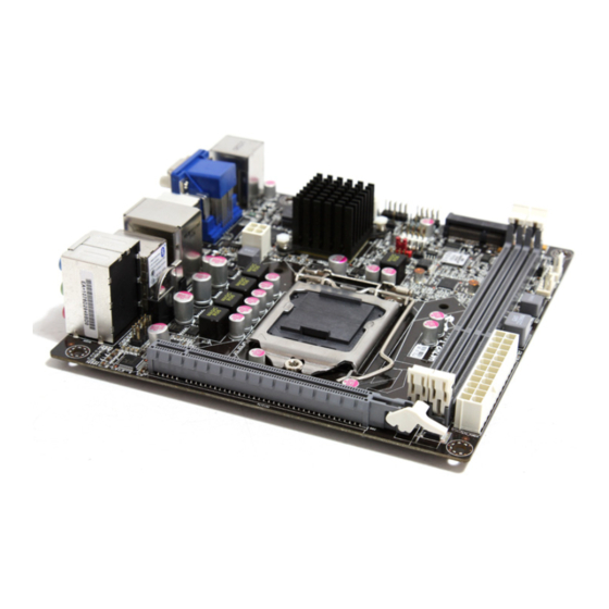
Page 9: Motherboard Components
Motherboard Components Introducing the Motherboard... - Page 10 Table of Motherboard Components LABEL COMPONENTS LGA1155 socket for latest new Core i7/i5/i3/ 1. CPU Socket Pentium/Celeron processors 2. SCN For Mini PCIE1X card or mSATA card 3. DDR3_1~2 240-pin DDR3 SDRAM slots 4. SYS_FAN System cooling fan connector 5. CPU_FAN CPU cooling fan connector 6.
-
Page 11: Installing The Motherboard
Chapter 2 Installing the Motherboard Safety Precautions • Follow these safety precautions when installing the motherboard • Wear a grounding strap attached to a grounded device to avoid dam- age from static electricity • Discharge static electricity by touching the metal case of a safely grounded object before working on the motherboard •... -
Page 12: Checking Jumper Settings
Do not over-tighten the screws as this can stress the motherboard. Checking Jumper Settings This section explains how to set jumpers for correct configuration of the motherboard. Setting Jumpers Use the motherboard jumpers to set system configuration options. Jumpers with more than one pin are numbered. -
Page 13: Checking Jumper Settings
Checking Jumper Settings The following illustration shows the location of the motherboard jumpers. Pin 1 is labeled. Jumper Settings Jumper Type Description Setting (default) 1-2: NORMAL 2-3: CLEAR CMOS 3-pin Clear CMOS CLR_CMOS CLR_CMOS Before clearing the CMOS, make sure to turn off the system. -
Page 14: Installing Hardware
Installing Hardware Installing the Processor Caution: When installing a CPU heatsink and cooling fan make sure that you DO NOT scratch the motherboard or any of the surface- mount resistors with the clip of the cooling fan. If the clip of the cooling fan scrapes across the motherboard, you may cause serious damage to the motherboard or its components. -
Page 15: Cpu Installation Procedure
CPU Installation Procedure The following illustration shows CPU installation components. A. Opening of the Load Plate · Put your thumb on the tail of the load plate and press the tail down. · Rotate the load plate to fully open position. -
Page 16: Installing Memory Modules
Installing Memory Modules This motherboard accommodates four memory modules. It can support two 240-pin DDR3 1333/1066. The total memory capacity is 8 GB. DDR3 SDRAM memory module table Memory module Memory Bus DDR3 1066 533 MHz DDR3 1333 667 MHz You must install at least one module in any of the two slots. -
Page 17: Expansion Slots
Expansion Slots Installing Add-on Cards The slots on this motherboard are designed to hold expansion cards and connect them to the system bus. Expansion slots are a means of adding or enhancing the motherboard’s features and capabilities. With these efficient facilities, you can in- crease the motherboard’s capabilities by adding hardware that performs tasks that are not part of the basic system. - Page 18 Follow these instructions to install an add-on card: Remove a blanking plate from the system case corresponding to the slot you are going to use. Install the edge connector of the add-on card into the expansion slot. Ensure that the edge connector is correctly seated in the slot. Secure the metal bracket of the card to the system case with a screw.
-
Page 19: Connecting Optional Devices
Connecting Optional Devices Refer to the following for information on connecting the motherboard’s optional devices: SATA1~2: Serial ATAIII connectors These connectors are used to support the new Serial ATAIII devices for the highest data transfer rates (6.0 Gb/s), simpler disk drive cabling and easier PC assembly. It doubles the transfer rate of current SATA 3.0Gb/s interface. - Page 20 F_AUDIO: Front Panel Audio header for Azalia This header allows the user to install auxiliary front-oriented microphone and line- out ports for easier access. Signal Name Signal Name PORT 1L AUD_GND PORT 1R PRESENCE# PORT 2R PORT1_JD AUD_GND PORT 2L PORT2_JD F_USB1~2: Front Panel USB 2.0 headers The motherboard has four USB 2.0 ports installed on the rear edge I/O port array.
- Page 21 COM: Onboard serial port header Connect a serial port extension bracket to this header to add a serial port to your system. Signal Name Function DCDB Data Carrier Detect SINB Serial Input SOUTB UART B Serial Output DTRB UART B Data Terminal Ready Ground DSRB Data Set Ready...
-
Page 22: Installing A Sata Hard Drive
Installing a SATA Hard Drive This section describes how to install SATA hard drives. About SATA Connectors Your motherboard features four SATA connectors supporting a total of four drives. SATA refers to Serial ATA (Advanced Technology Attachment) is the standard inter- face for the IDE hard drives which are currently used in most PCs. -
Page 23: Connecting I/O Devices
Connecting I/O Devices The backplane of the motherboard has the following I/O ports: HDMI port Connect the HDMI port to the HDMI devices. DVI Port Use the DVI port to connect the monitor. VGA Port Connect your monitor to the VGA port. LAN Port Connect RJ-45 jacks to LAN port to connect your computer to the Network. -
Page 24: Connecting Case Components
Connecting Case Components After you have installed the motherboard into a case, you can begin connecting the motherboard components. Refer to the following: Connect the CPU cooling fan cable to CPU_FAN. Connect the standard power supply connector to ATX_POWER. Connect the case switches and indicator LEDs to the F_PANEL. Connect the system cooling fan connector to SYS_FAN. - Page 25 Connecting 4-pin power cable The ATX12V4P power connector is used to provide power to the CPU. When installing 4-pin power cable, the latches of power cable and the ATX12V4P match perfectly. 4-pin power cable CPU_FAN: CPU Cooling FAN Power Connector Signal Name Function System Ground...
- Page 26 SPK: Internal speaker Signal Name Signal ATX12V4P: ATX 12V Power Connector Signal Name Ground Ground +12V +12V Installing the Motherboard...
-
Page 27: Front Panel Header
Front Panel Header The front panel header (F_PANEL) provides a standard set of switch and LED headers commonly found on ATX or micro-ATX cases. Refer to the table below for information: Signal Function Signal Function HD_LED_P Hard disk LED (+) FP PWR/SLP *MSG LED (+) HD_LED_N Hard disk LED (-) FP PWR/SLP *MSG LED (-) - Page 28 Memo Installing the Motherboard...
-
Page 29: Using Bios
Chapter 3 Using BIOS About the Setup Utility The computer uses the latest “American Megatrends Inc. ” BIOS with support for Windows Plug and Play. The CMOS chip on the motherboard contains the ROM setup instructions for configuring the motherboard BIOS. The BIOS (Basic Input and Output System) Setup Utility displays the system’s configuration status and provides you with options to set system parameters. -
Page 30: Resetting The Default Cmos Values
Press the delete key to access BIOS Setup Utility. Aptio Setup Utility - Copyright (C) 2010 American Megatrends, Inc. Main Advanced Chipset M.I.B III Boot Security Save & Exit Set the Date. Use Tab to BIOS Information switch between Data elements. System Language [English] System Date... -
Page 31: Bios Navigation Keys
In this manual, default values are enclosed in parenthesis. Submenu items are denoted by a triangle The default BIOS setting for this motherboard apply for most conditions with optimum performance. We do not suggest users change the default values in the BIOS setup and take no responsibility to any damage caused by changing the BIOS settings. -
Page 32: Advanced Menu
Legacy OpROM Support Option ROM Launch PXE OpROM [Disabled] Launch Storage OpROM [Enabled] LAN Configuration :Select Screen ECS eJIFFY Function PC Health Status :Select Item Power Management Setup Enter : Select ACPI Settings +/- : Change Opt. CPU Configuration F1:General Help... -
Page 33: Lan Configuration
F3:Optimized Defaults F4:Save & Exit ESC:Exit Version 2.02.1205. Copyright (C) 2010, American Megatrends, Inc. ECS eJIFFY Function (Disabled) This item allows you to enable or disable ECS eJIFFY Function. Press <Esc> to return to the Advanced Menu page. Using BIOS... -
Page 34: Pc Health Status
PC Health Status On motherboards support hardware monitoring, this item lets you monitor the paeameters for critical voltages, temperatures and fan speeds. Aptio Setup Utility - Copyright (C) 2010 American Megatrends, Inc. Main Advanced Chipset M.I.B III Boot Security Save & Exit Smart Fan Function System Temperature 43°C... - Page 35 Smart Fan Mode (Normal) This item allows you to select the fan mode (Normal, Quiet, Silent, or Manual) for a better operation environment. If you choose Normal mode, the fan speed will be auto adjusted depending on the CPU temperature. If you choose Quite mode, the fan speed will be auto minimized for quiet environment.
- Page 36 Power Management Setup This page sets up some parameters for system power management operation. Aptio Setup Utility - Copyright (C) 2010 American Megatrends, Inc. Main Advanced Chipset M.I.B III Boot Security Save & Exit Power Management Setup About Resume by Ring Resume By RING [Disabled] Resume By PCI-E/Lan PME...
-
Page 37: Acpi Configuration
ACPI Configuration The item in the menu shows the highest ACPI sleep state when the system enters suspend. Aptio Setup Utility - Copyright (C) 2010 American Megatrends, Inc. Main Advanced Chipset M.I.B III Boot Security Save & Exit ACPI Settings Select the highest ACPI sleep state the system will enter ACPI Sleep State... -
Page 38: Cpu Configuration
CPU Configuration The item in the menu shows the CPU . Aptio Setup Utility - Copyright (C) 2010 American Megatrends, Inc. Main Advanced Chipset M.I.B III Boot Security Save & Exit Disabled for Windows XP CPU Configuration Intel (R) Core (TM) i5-2500 CPU @ 3.30GHz EMT64 Supported Processor Speed... - Page 39 Excute Disable Bit (Enabled) This item allows the processor to classify areas in memory by where application code can execute and where it cannot. When a malicious worm attempts to insert code in the buffer, the processor disables code execution, preventing damage or worm propa- gation.
-
Page 40: Sata Configuration
SATA Configuration Use this item to show the mode of serial SATA configuration options. Aptio Setup Utility - Copyright (C) 2010 American Megatrends, Inc. Main Advanced Chipset M.I.B III Boot Security Save & Exit (1) IDE Mode. (2) AHCI Mode. SATA Configuration (3) RAID Mode. -
Page 41: Usb Configuration
USB Configuration Use this item to show the information of USB configuration. Aptio Setup Utility - Copyright (C) 2010 American Megatrends, Inc. Main Advanced Chipset M.I.B III Boot Security Save & Exit USB Configuration Enabled/Disabled All USB Devices All USB Devices [Enabled] USB 3.0 Controller [Enabled]... -
Page 42: Super Io Configuration
Super IO Configuration Use this item to show the information of Super IO configuration. Aptio Setup Utility - Copyright (C) 2010 American Megatrends, Inc. Main Advanced Chipset M.I.B III Boot Security Save & Exit Set Parameters of Serial Port Super IO Configuration 0 (COMA) Serial Port 0 Configuration :Select Screen... -
Page 43: Chipset Menu
Chipset Menu The chipset menu items allow you to change the settings for the North chipset, South chipset and other system. Aptio Setup Utility - Copyright (C) 2010 American Megatrends, Inc. Main Advanced Chipset M.I.B III Boot Security Save & Exit North Bridge Parameters North Bridge South Bridge... - Page 44 PEG Force Gen1 (Disabled) This item improve the compatibility for PCIEx16 slot support PCIEx1 devices. IGD Multi-Monitor (Disabled) This item enables or disables IGD(Internal Graphics device) multi-monitor. Press <Esc> to return to the chipset menu page. South Bridge Scroll to this item and press <Enter> to view the following screen. Aptio Setup Utility - Copyright (C) 2010 American Megatrends, Inc.
- Page 45 ME Subsystem Scroll to this item and press <Enter> to view the following screen. Aptio Setup Utility - Copyright (C) 2010 American Megatrends, Inc. Main Advanced Chipset M.I.B III Boot Security Save & Exit Intel ME Subsytem Configuration ME Subsystem Help ME Version 7.0.0.1141 ME Subsystem...
-
Page 46: M.i.b Iii (Mb Intelligent Bios Iii) Menu
M.I.B III (MB Intelligent BIOS III) Menu This page enables you to set the clock speed and system bus for your system. The clock speed and system bus are determined by the kind of processor you have installed in your system. Aptio Setup Utility - Copyright (C) 2010 American Megatrends, Inc. - Page 47 Current ICC Profiles Index (N/A) This item shows current ICC profiles index. ICC Enable (Disabled) This item allows you to enable or disable current ICC. Press <Esc> to return to the M.I.B III menu page. Performance Tunning Scroll to this item to view the following screen: Aptio Setup Utility - Copyright (C) 2010 American Megatrends, Inc.
- Page 48 CPU Ratio This item shows non turbo CPU ratio. IA Core Current (Normal) Use this item to control CPU Current Limit. This is for Turbo mode. Power Limit 1 Value (Watt) (95) Use this item to control the limit of the TDP. This is for Turbo mode. Power Limit 2 Switch (Enabled) Use this item to control the Power Limit 2.
- Page 49 Chipset Configuration Scroll to this item to view the following screen: Aptio Setup Utility - Copyright (C) 2010 American Megatrends, Inc. Main Advanced Chipset M.I.B III Boot Security Save & Exit Disabled/Enabled GT OverClocking Memory Multiplier Configuration Memory Mutiplier [10.67] :Select Screen Memory Timing Configuration :Select Item...
- Page 50 Aptio Setup Utility - Copyright (C) 2010 American Megatrends, Inc. Main Advanced Chipset M.I.B III Boot Security Save & Exit Disabled/Enabled GT OverClocking Memory Multiplier Configuration Memory Mutiplier [10.67] :Select Screen Memory Timing Configuration :Select Item Enter : Select CAS# Latency (tCL) Row Precharge Time (tRP) +/- : Change Opt.
-
Page 51: Boot Menu
Boot Menu This page enables you to set the keyboard NumLock state. Aptio Setup Utility - Copyright (C) 2010 American Megatrends, Inc. Main Advanced Chipset M.I.B III Boot Security Save & Exit Select the keyboard NumLock Boot Configuration state Bootup NumLock State [On] Boot Option Priorities :Select Screen... -
Page 52: Security Menu
Security Menu This page enables you to set setup administrator and password. Aptio Setup Utility - Copyright (C) 2010 American Megatrends, Inc. Main Advanced Chipset M.I.B III Boot Security Save & Exit Set Setup Administrator If ONLY the Administrator’s password is set, Password then this only limits access to Setup and is only asked for when entering Setup. -
Page 53: Save & Exit Menu
Save & Exit Menu This page enables you to exit system setup after saving or without saving the changes. Aptio Setup Utility - Copyright (C) 2010 American Megatrends, Inc. Main Advanced Chipset M.I.B III Boot Security Save & Exit Exit system setup after saving Save Changes and Exit the changes. - Page 54 Boot Override Use this item enables you to set the device order. Aptio Setup Utility - Copyright (C) 2010 American Megatrends, Inc. Main Advanced Chipset M.I.B III Boot Security Save & Exit Exit system setup after saving Save Changes and Exit the changes.
-
Page 55: Updating The Bios
Updating the BIOS You can download and install updated BIOS for this motherboard from the manufacturer’s Web site. New BIOS provides support for new peripherals, improve- ments in performance, or fixes for known bugs. Install new BIOS as follows: If your motherboard has a BIOS protection jumper, change the setting to allow BIOS flashing. - Page 56 Memo...
-
Page 57: Using The Motherboard Software
Chapter 4 Using the Motherboard Software About the Software DVD-ROM/CD-ROM The support software DVD-ROM/CD-ROM that is included in the motherboard package contains all the drivers and utility programs needed to properly run the bundled products. Below you can find a brief description of each software program, and the location for your motherboard version. -
Page 58: Running Setup
Drivers Tab Setup Click the Setup button to run the software installation program. Select from the menu which software you want to install. Browse CD The Browse CD button is the standard Windows command that al- lows you to open Windows Explorer and show the contents of the support disk. - Page 59 Click Next. The following screen appears: Check the box next to the items you want to install. The default options are recom- mended. Click Next run the Installation Wizard. An item installation screen appears: Follow the instructions on the screen to install the items. Drivers and software are automatically installed in sequence.
-
Page 60: Manual Installation
Windows Vista/7 will appear below UAC (User Account Control) message after the system restart. You must select “Allow” to install the next driver. Continue this process to complete the drivers installation. Manual Installation Insert the disk in the DVD-ROM/CD-ROM drive and locate the PATH.DOC file in the root directory. -
Page 61: Setting Up Ejiffy
Note: eJIFFY is ECS optional feature utility corresponding to the DVD activation and BIOS setup. Please check the hard copy user’s guide or product color-box to see if the model has embodded eJIFFY feature. -
Page 62: Installation And Bios Setup
DVD Activation Finish the DVD utility setup, and then set the BIOS to complete eJIFFY activation. 1. Insert ECS software utility DVD and enter below “Utilities” screen. Click eJIFFY feature item to install. 2. Follow the onscreen instructions to finish eJIFFY setup. - Page 63 3. After setting up eJIFFY under Windows, you can switch eJIFFY display/keyboard language from English to your local language. The changes will be applied after rebooting. Note: The keyboard language selection list offers several more regional keyboard setups to switch with the default English typing. Please refer to the usage FAQ for more tips.
- Page 64 Setup button on the post screen to enter the BIOS setup page after boot up. 5. And then enter the Advanced Setup page to enable the item ECS eJIFFY Func- tion. Press F10 to save the configuration and exit. Restart your computer.
-
Page 65: Entering Ejiffy
Entering eJIFFY The post screen appears within several seconds after boot up and it has three buttons on it, Operating system, eJIFFY and BIOS Setup. Click to enter the normal OS you have installed such as Windows. Click to enter eJIFFY OS. Click to set the BIOS. -
Page 66: Features Icons
Feature Icons The following illustration shows the main feature icons that eJIFFY provides on the menu. eWeb: Firefox for web browsing/webmail and watching flash video. ePix: Photo viewing. ePal: On-line chat tool to use the most popular IMs in the world. (MSN, ICQ , AIM, etc.) Shows ePal on-line connection status. -
Page 67: Usage Faq
Usage FAQ Language Control Panel: Besides setting English as the default interface, eJIFFY offers multi-language displays and keyboard settings for language- switch. Open the language control panel to select a preferable language setting. Keyboard Language Setup to open the language control panel. Step1. - Page 68 Step 2: Click “Keyboard Language” icon to open the keyboard selection list, which offers several regional keyboard settings besides default English keyboard. Step 3: Click the selected keyboard language (e.g. French) and press “OK”. Setting Up eJIFFY...
- Page 69 Tips for Language Switch: Tip 1: Click “Change Keyboard” icon to switch the typing language. The typing language on text box will switch to the selected one: Click again to switch to English typing back. Tip 2. If you use the default English keyboard, eJIFFY still offers other language inputs to switch with English.
- Page 70 Setting Up eJIFFY...
- Page 71 Setting Up eJIFFY...
- Page 72 Tip 3. How to change display language? Open the Language Control Panel and click to show the display language list. Check your desired display language. Your selected display language will be applied after rebooting. Setting Up eJIFFY...
-
Page 73: Usage Faq
eWeb: Firefox for web browsing/webmail and watching flash video. Q1: How to download files to hard disk through eWeb? Click on the file link directly. Then select “Save File” in the pop-up window. 1. Before downloading files, please “mount” the storage devices to make Note: sure the device is connected with eJIFFY interface. - Page 74 Q2: How to save image file through eWeb? 1. Select the image you want to save and press the right key of your mouse to show the menu, then click the option “ Save Image As” from the menu. 2. Then the “Save Image” window appears. You may rename the image file in the “Name”...
- Page 75 ePix: Photo viewing. Q1: How to find image files saved in hard disk through ePix? Enter the ePix window, then click the icon “Folder” located in the upper left-hand corner, then follow the path for the files you have saved to view the image files. Setting Up eJIFFY...
- Page 76 Q2: How to use the fit function under slide show? 1. Click “Edit” and select “Preferences” option from the menu. 2. Click “Viewer” and choose “Keep previous zoom” in “After loading an im- age”. Close the window and you can use the fit function under slide show now. Note: ePix supports to view image files only.
- Page 77 Mount/Unmount Disk. Q1: What does it mean for “Mount Disk”? “ Mount” means to connect the storage devices to eJIFFY interface. After plugging the external device to the computer such as USB drives, a new disk icon will appear as the following picture shows. Please click the “mount” prompt on the icon.
- Page 78 Memo Setting Up eJIFFY...
-
Page 79: Trouble Shooting
Chapter 6 Trouble Shooting Start up problems during assembly After assembling the PC for the first time you may experience some start up problems. Before calling for technical support or returning for warranty, this chapter may help to address some of the common questions using some basic troubleshooting tips. -
Page 80: Start Up Problems After Prolong Use
c) The PC suddenly shuts down while booting up. 1. The CPU may experience overheating so it will shutdown to protect itself. Ensure the CPU fan is working properly. 2. From the BIOS setting, try to disable the Smartfan function to let the fan run at default speed. - Page 82 Memo Trouble Shooting...
Need help?
Do you have a question about the H67H2-1 and is the answer not in the manual?
Questions and answers