Sign In
Upload
Manuals
Brands
HP Manuals
Measuring Instruments
1660 Series
HP 1660 Series Manuals
Manuals and User Guides for HP 1660 Series. We have
2
HP 1660 Series manuals available for free PDF download: Service Manual, Training Manual
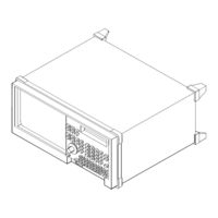
HP 1660 Series Service Manual (223 pages)
Logic Analyzers
Brand:
HP
| Category:
Measuring Instruments
| Size: 8.08 MB
Table of Contents
Table of Contents
6
Accessories
13
Specifications (Logic Analyzer)
14
Specifications (Oscilloscope)
15
Characteristics (Logic Analyzer)
16
Characteristics (Oscilloscope)
16
Supplemental Characteristics (Logic Analyzer)
17
Supplemental Characteristics (Oscilloscope)
20
Recommended Test Equipment (Logic Analyzer)
24
Recommended Test Equipment (Oscilloscope)
25
To Inspect the Logic Analyzer
27
To Apply Power
28
To Operate the User Interface
28
To Set the Line Voltage
28
To Degauss the Display
29
To Clean the Logic Analyzer
29
To Test the Logic Analyzer
29
To Perform the Self-Tests
32
To Make the Test Connectors (Logic Analyzer)
35
To Test the Threshold Accuracy (Logic Analyzer)
37
Set up the Equipment
37
Set up the Logic Analyzer
38
Connect the Logic Analyzer
38
Test the TTL Threshold
39
Test the ECL Threshold
41
Test the - User Threshold
42
Test the 0 V User Threshold
44
Test the Next Pod
45
To Test the Glitch Capture (Logic Analyzer)
46
Set up the Equipment
46
Set up the Logic Analyzer
47
Connect the Logic Analyzer
47
Test the Glitch Capture on the Connected Channels
49
Test the Next Channels
51
To Test the Single-Clock, Single-Edge, State Acquisition (Logic Analyzer)
52
Set up the Equipment
52
Set up the Logic Analyzer
53
Connect the Logic Analyzer
55
Verify the Test Signal
57
Check the Setup/Hold Combination
59
Test the Next Channels
63
To Test the Multiple-Clock, Multiple-Edge, State Acquisition (Logic Analyzer)
64
Set up the Equipment
64
Set up the Logic Analyzer
65
Connect the Logic Analyzer
67
Verify the Test Signal
69
Check the Setup/Hold with Single Clock Edges, Multiple Clocks
71
Test the Next Channels
75
To Test the Single-Clock, Multiple-Edge, State Acquisition (Logic Analyzer)
76
Set up the Equipment
76
Set up the Logic Analyzer
77
Connect the Logic Analyzer
79
Verify the Test Signal
81
Check the Setup/Hold with Single Clock, Multiple Clock Edges
83
Test the Next Channels
87
To Test the Time Interval Accuracy (Logic Analyzer)
88
Set up the Equipment
88
Set up the Logic Analyzer
89
Connect the Logic Analyzer
91
Acquire the Data
92
To Test the CAL OUTPUT Ports (Oscilloscope)
93
Set up the Equipment
93
Set up the Logic Analyzer
94
Verify the DC CAL OUTPUT Port
95
Set up the Logic Analyzer
96
Verify the AC CAL OUTPUT Port
96
To Test the Input Resistance (Oscilloscope)
97
Set up the Equipment
97
Set up the Logic Analyzer
98
Connect the Logic Analyzer
99
Acquire the Data
100
Perform an Operational Accuracy Calibration
100
To Test the Voltage Measurement Accuracy (Oscilloscope)
101
Set up the Equipment
101
Set up the Logic Analyzer
102
Connect the Logic Analyzer
103
Acquire the Data
104
To Test the Offset Accuracy (Oscilloscope)
105
Set up the Equipment
105
Set up the Logic Analyzer
106
Connect the Logic Analyzer
107
Acquire the Zero Input Data
108
Acquire the DC Input Data
109
To Test the Bandwidth (Oscilloscope)
110
Set up the Equipment
110
Set up the Logic Analyzer
111
Connect the Logic Analyzer
113
Acquire the Data
114
To Test the Time Measurement Accuracy (Oscilloscope)
115
Set up the Equipment
115
Set up the Logic Analyzer
116
Connect the Logic Analyzer
118
Acquire the Data
118
To Test the Trigger Sensitivity (Oscilloscope)
119
Set up the Equipment
119
Set up the Logic Analyzer
120
Connect the Logic Analyzer
122
Acquire the Data
122
Performance Test Record (Logic Analyzer)
123
Performance Test Record (Oscilloscope)
130
Calibrating and Adjusting
134
Logic Analyzer Calibration
135
To Calibrate the Oscilloscope
136
Set up the Equipment
136
Load the Default Calibration Factors
137
Self Cal Menu Calibrations
138
To Adjust the CRT Monitor Alignment
139
To Adjust the CRT Intensity
141
To Use the Flowcharts
145
To Check the Power-Up Tests
158
To Run the Self-Tests
159
To Test the Power Supply Voltages
165
To Test the CRT Monitor Signals
167
To Test the Keyboard Signals
168
To Test the Disk Drive Voltages
169
To Perform the BNC Test
171
To Test the Logic Analyzer Probe Cables
172
To Test the Auxiliary Power
176
To Remove and Replace the Handle
182
To Remove and Replace the Feet and Tilt Stand
182
To Remove and Replace the Cover
182
To Remove and Replace the Disk Drive
183
Power Supply
183
CPU Board
183
To Remove and Replace the Power Supply
184
To Remove and Replace the CPU Board
184
To Remove and Replace the Switch Actuator Assembly
185
To Remove and Replace the Rear Panel Assembly
186
Acquisition Board ( Oscilloscope Board for HP 1660AS-Series)
186
To Remove and Replace the Acquisition Board ( Oscilloscope Board for HP 1660AS-Series)
187
To Remove and Replace the Front Panel and Keyboard
188
To Remove and Replace the Intensity Adjustment
188
To Remove and Replace the Monitor
189
To Remove and Replace the Handle Plate
189
To Remove and Replace the Fan
190
To Remove and Replace the Line Filter
190
To Remove and Replace the HP-IB and RS-232C Cables
191
To Return Assemblies
192
Replaceable Parts Ordering
195
Exploded View
196
Replaceable Parts List
197
Power Cables and Plug Configurations
201
Block-Level Theory
204
The HP 1660 Series Logic Analyzer
204
The Logic Acquisition Board
207
The Oscilloscope Board
210
Self-Tests Description
213
Power-Up Self-Tests
213
System Tests (System PV)
214
Analyzer Tests (Analy PV)
217
Oscilloscope Tests (Scope PV)
219
Hp-Ib
220
Advertisement
HP 1660 Series Training Manual (140 pages)
Training Kit for Logic Analyzers
Brand:
HP
| Category:
Measuring Instruments
| Size: 5.77 MB
Table of Contents
Table of Contents
7
Using the Analyzer and Understanding the Measurement Process
11
Using the Analyzer
13
Understanding the Measurement Process
14
Introduction to Timing Analysis
19
Before You Begin
21
Put the Analyzer into Timing Mode
22
Change a Label Name
23
Modify Channel Assignments
24
Define a Term for the Timing Trigger
25
Set up the Trigger Specification
26
Trigger on the Term and Examine the Waveform
27
Introduction to State Analysis
29
Before You Begin
31
Put the Analyzer into State Mode
32
Set up the State Clock
33
Change a Label Name
34
Modify Channel Assignments
35
Define a Term for the State Trigger
36
Set up Level 1 of the State Trigger Specification
37
Set up Level 2 of the State Trigger Specification
38
Run the State Analyzer and View and Change the State Listing
39
Create Symbols to Display State Data
40
Create Additional Symbols
41
Select and View Symbols in the State Listing
42
Comparing State Traces before You Begin
45
Check the Configuration
46
Set up the State Trigger Specification
47
Run the Analyzer and View the State Listing
48
Copy the State Listing to the Compare Reference Listing
49
Change the Jumper to Acquire a Different State Listing
50
Run the Analyzer and Find the Errors
51
Mixed Mode - Correlation of State and Timing Data
53
Before You Begin
55
Connect the Timing Analyzer
56
Put the Analyzer into State and Timing Modes
57
Change a Label Name and Modify Channel Assignments
58
Turn on the TCOUNT Label in the Waveform Menu
58
Clear the Timing Analyzer Trigger
59
Set up the State Trigger Specification
59
Enable Time Correlation between the Timing and State Analyzers
60
Arm the Timing Analyzer with the State Analyzer
61
View the Mixed-Mode Display with Time-Correlated Markers
62
Advanced State Triggering
63
Before You Begin
65
Put the Analyzer into State Mode
66
Define State Trigger Terms "A" through "D
67
Define State Trigger Term "E" and Range1
68
Add State Trigger Sequence Levels
69
Set up Level 1 of the State Trigger Specification
70
Set up Level 2 of the State Trigger Specification
71
Set up Level 3 of the State Trigger Specification
72
Set up Level 4 of the State Trigger Specification and Define a Combination Trigger Term
73
Check the Trigger Specification
75
Run the State Analyzer and View the Data
76
Using the Oscilloscope
79
Before You Begin
81
Connect the Channel 1 Oscilloscope Probe
82
Get the Waveform on the Display
83
Delete Channel 2 from the Display
84
Zoom and Scroll through the Clock Waveform
85
Measure the Clock Period Manually
86
Measure the Clock Period with Auto Measure
87
Read Voltage with the Markers
88
Triggering the Oscilloscope with the Timing Analyzer
89
Before You Begin
91
Set the Jumpers
92
Connect the Oscilloscope Probe
93
Get the Waveform on the Display
94
Change the Oscilloscope Trigger
95
Turn on the Timing Analyzer
96
Set up the Timing Format Menu
97
Define the Timing Trigger Term "Edge 1
98
Set up the Timing Trigger Specification
99
Arm the Oscilloscope with the Timing Analyzer
100
Add Oscilloscope Waveform to the Timing Waveforms
101
Capture the Glitch with the Timing Analyzer and Oscilloscope
102
Align the Glitch Displayed by the Oscilloscope and Analyzer
103
Using the Pattern Generator
105
Before You Begin
107
Connect the Pattern Generator
108
Turn on the Timing Analyzer
109
Change a Label Name
110
Modify Channel Assignments
111
Set up the Timing Analyzer Trigger Term
112
Add a Pattern Generator Label to the Timing Waveform Display
113
Set up the Pattern Generator Format Menu
114
Program the Pattern Generator Output
116
Add Program Lines
117
Start the Pattern Generator and View the Walking Ones Pattern
118
Stop the Pattern Generator
119
Introduction to Inverse Assembly
121
Load the Inverse Assembler and Sample Listing
123
View the Address, Data, and Status Labels
124
View the Assembly Listing
125
Filter the Captured Data
126
Setting the Jumpers and Loading the Configurations
127
To Set the Jumpers
129
To Load a Configuration File
131
All about the Logic Analyzer Training Board
133
Power Source
134
Circuit Description
134
Jumpers
135
Schematic
136
Advertisement
Related Products
HP 1660CS-Series
HP 1660CS
HP HP 1660CP Series
HP 1660E Series
HP 1660ES Series
HP 1660EP Series
HP 1660A Series
HP 1660AS Series
HP 1660C Series
HP 1663CS
HP Categories
Desktop
Laptop
Server
Monitor
Switch
More HP Manuals
Login
Sign In
OR
Sign in with Facebook
Sign in with Google
Upload manual
Upload from disk
Upload from URL