Sign In
Upload
Manuals
Brands
ABB Manuals
Measuring Instruments
Aztec 600
ABB Aztec 600 Manuals
Manuals and User Guides for ABB Aztec 600. We have
5
ABB Aztec 600 manuals available for free PDF download: Manual, User Manual, Operating Instruction
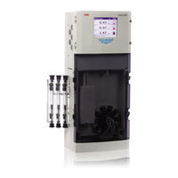
ABB Aztec 600 User Manual (109 pages)
aluminium, ammonia, color, iron, manganese, phosphate Single- and multi-stream colorimetric analyzers
Brand:
ABB
| Category:
Measuring Instruments
| Size: 3.14 MB
Table of Contents
Table of Contents
3
1 Safety
6
Health & Safety
6
Electrical Safety - CEI/IEC 61010-1:2001-2
6
Symbols - CEI/IEC 61010-1:2001-2
7
Product Recycling Information
8
Product Disposal
8
Restriction of Hazardous Substances (Rohs)
8
Chemical Reagents
8
Safety Precautions
8
Safety Conventions
9
Safety Recommendations
9
Service and Repairs
9
Potential Safety Hazards
9
2 Introduction
10
Operator Display Overview
11
See Section 6
11
3 Getting Started
13
Overview
13
On-Line Help
14
4 Installation
15
Optional Accessories
15
Sampling Requirements
15
Location
15
Mounting
16
Reagent Mounting Tray (Option)
16
Dimensions
17
Electrical Connections
18
Access to Connections
19
Ethernet Connections
20
Connections Overview
21
Replacing the DC Fuse
22
Alarm Relay Contact Protection and Interference Suppression
22
Connecting Sample and Reagents
23
Connecting Sample Inlet and Drain Line(S)
23
Installing Reagents and Reagent Level Sensors
24
Connecting the Analyzer Waste
24
5 Operation
25
Front Panel Controls
25
Navigation and Editing
25
Text Editing
25
Numeric Editing
26
Other Methods of Editing
26
Menus
26
Software Screen Structure
26
Indicator View Menus
26
Chart View Menus
26
6 Configuration
27
Common
29
Setup
29
Screen
29
Time
30
Security
31
User
34
Operator Messages
34
Measurement
35
Setup
35
Streams
35
Clean
35
Calibration
36
Setup
36
Zero Compensation (Aztec 600 Color Only)
36
Alarm Relays
37
Current Outputs
39
Outputs 1 to 6
39
Output Calibration
39
Logging
40
Chart
40
Ranges
40
Archive
41
Communications
42
Ethernet
42
E-Mail 1 and E-Mail 2
43
Profibus
43
Commissioning
44
Setup
44
7 Logging
45
See Section 7
45
SD Cards
46
SD Card Insertion/Removal
46
External Media Status Icons
47
Reset Archiving
47
File Viewer
47
Archive File Types
47
Text Format Data Files
48
Text Format Stream Data Filenames
49
Text Format Stream Data - Example Filenames
49
Text Format Log Files (Audit and Alarm Log)
50
Daylight Saving
50
Text Format Data Verification and Integrity
50
Binary Format Data Files
50
Binary Format Data Filenames
50
Binary Format Stream Files
51
Binary Format Log Files
51
Daylight Saving
51
Binary Format Data Verification and Integrity
51
8 Chart Functions
52
Historical Review
52
Operator Messages
52
Chart Annotation
52
See Section 8
52
Screen Interval
53
Scales
53
Trace Select
53
9 Operate
54
Stop Monitor
54
Start Monitor Measurement
54
Calibrate
54
Prime Lines and Calibrate
54
Flush Monitor
54
See Section 9
54
10 Diagnostics
55
Monitor Status
55
Status
55
See Section 10
55
Cal
56
I/O
56
Info
56
Cell Diagnostics
57
Relay Test
57
Current Output Test
57
11 Statistics
58
12 Diagnostic Information and Icons
59
Analyzer Diagnostic Information
59
Alarm Acknowledge
64
Audit Log and Alarm Event Log
64
Audit Log - Icons
64
See Section 12.2
64
Alarm Event Log - Icons
65
Status Icons
65
13 Maintenance
66
Changing Reagents
66
Regular Visual Checks
67
Annual Maintenance
67
Annual Maintenance Schedule
67
Annual Maintenance Kits
67
Maintenance Tools Required
67
Replacing the Valve Diaphragms
67
Replacing the Tubing
70
Replacing the Piston Tube and Piston Assembly
73
Completion
76
14 Specification
77
Appendix A - Reagents
80
Reagent Solutions
80
Reagent Storage
80
Reagent Consumption
80
Consumption of Sample, Standards and Dilution Water
81
Cleaning Solutions
81
Appendix B - Troubleshooting
82
Analyzer Malfunction
82
Cell Diagnostics
82
Effects of Loss of Power to the Analyzer
82
Simple Checks
83
Unstable or Erratic Readings
83
High/Low Measured Values
85
Excessive Usage of Reagent(S)
86
Calibration Failure
87
Appendix C - Principle of Operation
88
General Operation
88
Temperature Control
89
Measurement Cycle
89
Calibration Cycle
89
LED Calibration
89
Dilution Cycle
89
Chemical Measurement Methods Used
90
Typical Analyzer Calibration Data
92
Appendix D - Web Server
93
Stream Values
93
Operate
94
Monitor Status
94
Statistics
94
Logging Status
94
Operator Message
94
Configuration
95
FTP Access
95
FTP Access Via Internet Explorer
95
FTP Access Via Datamanager
96
File Transfer Program
96
Appendix E - Updating the Software
97
Appendix F - Spare Parts
98
Maintenance Kits
98
Upgrade Kits
98
Reagents and Reagent Bottles
98
Strategic Spares
100
Valve Assemblies and Associated Parts
100
F.4 Strategic Spares
100
Side Sample Pot Assemblies and Associated Parts
101
Measurement Head Assemblies and Associated Parts
102
Plumbing and Tubing
104
Electronic Boards
105
Accessories
106
F.5 Accessories
106
Notes
109
Advertisement
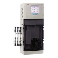
ABB Aztec 600 Manual (110 pages)
Single- and multi-stream colorimetric analyzers
Brand:
ABB
| Category:
Measuring Instruments
| Size: 2.51 MB
Table of Contents
Table of Contents
3
Safety
5
Health & Safety
5
Electrical Safety - CEI/IEC 61010-1:2001-2
5
Symbols - CEI/IEC 61010-1:2001-2
6
Product Recycling Information
7
Product Disposal
7
Restriction of Hazardous Substances (Rohs)
7
Chemical Reagents
7
Safety Precautions
7
Safety Conventions
8
Safety Recommendations
8
Service and Repairs
8
Potential Safety Hazards
8
Introduction
9
Operator Display Overview
10
Getting Started
12
Overview
12
On-Line Help
13
Installation
14
Optional Accessories
14
Sampling Requirements
14
Location
14
Mounting
15
Reagent Mounting Tray (Option)
15
Dimensions
16
Electrical Connections
17
Access to Connections
18
Ethernet Connections
19
Connections Overview
20
Replacing the DC Fuse
21
Alarm Relay Contact Protection and Interference Suppression
21
Connecting Sample and Reagents
22
Connecting Sample Inlet and Drain Line(S)
22
Installing Reagents and Reagent Level Sensors
23
Connecting the Analyzer Waste
23
Operation
24
Front Panel Controls
24
Navigation and Editing
24
Text Editing
24
Numeric Editing
25
Other Methods of Editing
25
Menus
25
Software Screen Structure
25
Indicator View Menus
25
Chart View Menus
25
Configuration
26
Common
28
Setup
28
Screen
28
Time
29
Security
30
User
33
Operator Messages
33
Measurement
34
Setup
34
Streams
34
Clean
34
Calibration
35
Setup
35
Zero Compensation (Aztec 600 Color Only)
35
Alarm Relays
36
Current Outputs
38
Outputs 1 to 6
38
Output Calibration
38
Logging
39
Chart
39
Ranges
39
Archive
40
Communications
41
Ethernet
41
E-Mail 1 and E-Mail 2
42
Profibus
42
Commissioning
43
Setup
43
Logging
44
SD Cards
45
SD Card Insertion/Removal
45
External Media Status Icons
46
Reset Archiving
46
File Viewer
46
Archive File Types
46
Text Format Data Files
47
Text Format Stream Data Filenames
48
Text Format Stream Data - Example Filenames
48
Text Format Log Files (Audit and Alarm Log)
49
Daylight Saving
49
Text Format Data Verification and Integrity
49
Binary Format Data Files
49
Binary Format Data Filenames
49
Binary Format Stream Files
50
Binary Format Log Files
50
Daylight Saving
50
Binary Format Data Verification and Integrity
50
Chart Functions
51
Historical Review
51
Operator Messages
51
Chart Annotation
51
Screen Interval
52
Scales
52
Trace Select
52
Operate
53
Stop Monitor
53
Start Monitor Measurement
53
Calibrate
53
Prime Lines and Calibrate
53
Flush Monitor
53
Diagnostics
54
Monitor Status
54
Status
54
Cal
55
I/O
55
Info
55
Cell Diagnostics
56
Relay Test
56
Current Output Test
56
Statistics
57
Diagnostic Information and Icons
58
Analyzer Diagnostic Information
58
Alarm Acknowledge
63
Audit Log and Alarm Event Log
63
Audit Log - Icons
63
Alarm Event Log - Icons
64
Status Icons
64
Maintenance
65
Changing Reagents
65
Regular Visual Checks
66
Annual Maintenance
66
Annual Maintenance Schedule
66
Annual Maintenance Kits
66
Maintenance Tools Required
66
Replacing the Valve Diaphragms
66
Replacing the Tubing
69
Replacing the Piston Tube and Piston Assembly
72
Completion
75
Specification
76
Appendix A - Reagents
79
Reagent Solutions
79
Reagent Storage
79
Reagent Consumption
79
Consumption of Sample, Standards and Dilution Water
80
Cleaning Solutions
80
Appendix B - Troubleshooting
81
Analyzer Malfunction
81
Cell Diagnostics
81
Effects of Loss of Power to the Analyzer
81
Simple Checks
82
Unstable or Erratic Readings
82
High/Low Measured Values
84
Excessive Usage of Reagent(S)
85
Calibration Failure
86
Appendix C - Principle of Operation
87
General Operation
87
Temperature Control
88
Measurement Cycle
88
Calibration Cycle
88
LED Calibration
88
Dilution Cycle
88
Chemical Measurement Methods Used
89
Typical Analyzer Calibration Data
91
Appendix D - Web Server
92
Stream Values
92
Operate
93
Monitor Status
93
Statistics
93
Logging Status
93
Operator Message
93
Configuration
94
FTP Access
94
FTP Access Via Internet Explorer
94
FTP Access Via Datamanager
95
File Transfer Program
95
Appendix E - Updating the Software
96
Appendix F - Spare Parts
98
Maintenance Kits
98
Upgrade Kits
98
Reagents and Reagent Bottles
98
Strategic Spares
100
Valve Assemblies and Associated Parts
100
Side Sample Pot Assemblies and Associated Parts
101
Measurement Head Assemblies and Associated Parts
102
Plumbing and Tubing
104
Electronic Boards
105
Transmitter Assembly
105
Accessories
106
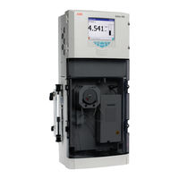
ABB Aztec 600 Operating Instruction (102 pages)
ISE ammonia and flouride, Single-stream ion-selective analyzers
Brand:
ABB
| Category:
Measuring Instruments
| Size: 6.98 MB
Table of Contents
Table of Contents
2
1 Safety
5
Health & Safety
5
Electrical Safety - CEI / IEC 61010-1:2001-2
5
Symbols - CEI / IEC 61010-1:2001-2
6
Product Recycling Information
7
Product Disposal
7
Restriction of Hazardous Substances (Rohs)
7
Chemical Reagents
7
Safety Precautions
7
Safety Conventions
8
Safety Recommendations
8
Service and Repairs
8
Potential Safety Hazards
8
2 Introduction
9
Operator Display Overview
10
See Section 6
10
3 Installation
12
Optional Accessories
12
Sampling Requirements
12
Location
12
Mounting
13
Mounting Dimensions
13
Mounting the Analyzer
14
Mounting the Optional Reagent Tray
14
Electrical Connections
15
Connections Overview
16
General Connections
17
Ethernet Connection
18
Alarm Relay Contact Protection and Interference Suppression
18
Preparing the Analytical Section
19
Connecting Sample Inlet and Drain Lines
19
Connecting the Waste Line
19
Fitting Peristaltic Pump Pressure Plate
20
Connecting Reagent and Calibration Solutions
21
Ammonia Probe Preparation
22
Fluoride Probe Preparation
23
Fitting the Probe
23
4 Getting Started
24
Overview
24
On-Line Help
25
5 Operation
26
Front Panel Controls
26
Navigation and Editing
26
Text Editing
26
Numeric Editing
27
Other Methods of Editing
27
Menus
27
Software Screen Structure
27
Indicator View Menus
27
Chart View Menus
27
6 Configuration
28
Common
30
Setup
30
Screen
30
Time
31
Security
32
User
35
Operator Messages
35
Measurement
36
Setup
36
Streams
36
Calibration
37
Setup
37
Alarm Relays
38
Current Outputs
40
Outputs 1 to 6
40
Output Calibration
40
Logging
41
Chart
41
Recording
41
Ranges
41
Archive
42
Communications
43
Ethernet
43
E-Mail 1 and E-Mail 2
44
Profibus
44
Commissioning
45
Setup
45
7 Logging
46
See Section 7
46
SD Cards
47
SD Card Insertion / Removal
47
External Media Status Icons
48
Reset Archiving
48
File Viewer
48
Archive File Types
48
Text Format Data Files
49
Text Format Stream Data Filenames
50
Text Format Stream Data - Example Filenames
50
Text Format Log Files (Audit and Alarm Log)
51
Daylight Saving
51
Text Format Data Verification and Integrity
51
Binary Format Data Files
51
Binary Format Data Filenames
51
Binary Format Stream Files
52
Binary Format Log Files
52
Daylight Saving
52
Binary Format Data Verification and Integrity
52
8 Chart Functions
53
Historical Review
53
Operator Messages
53
Chart Annotation
53
See Section 8
53
Screen Interval
54
9 Operate
55
Stop Monitor
55
Start Monitor Measurement
55
Calibrate
55
Prime Lines and Calibrate
55
Flush Monitor
55
See Section 9
55
10 Diagnostics
56
Monitor Status
56
Status
56
See Section 10
56
Cal
57
I / O
57
Info
57
Cell Diagnostics
58
Relay Test
58
Current Output Test
58
11 Statistics
59
12 Diagnostic Information and Icons
60
Analyzer Diagnostic Information
60
Alarm Acknowledge
64
Audit Log and Alarm Event Log
64
Audit Log - Icons
64
See Section 12.2
64
Alarm Event Log - Icons
65
Status Icons
65
13 Maintenance
66
Changing Reagents and Standard Solutions
66
Regular Visual Checks
67
Annual Maintenance
67
Replacing Pump Tubing and Capstans
67
Replacing Analyzer Tubing
69
Replacing Ammonia Probe Membrane
70
Replacing the DC Fuse
71
14 Specification - Aztec ISE Ammonia
72
15 Specification - Aztec ISE Fluoride
75
Appendix A - Reagents and Standard Solutions
78
Reagent and Standard Solutions - Ammonia-ISE
78
Reagent
78
Standard Solutions
78
Reagent and Standard Solutions - Fluoride-ISE
78
Reagent and Standard Solution Consumption
78
Appendix B - Troubleshooting
79
Analyzer Malfunction
79
Reagent and Standard Solutions
79
Probe Malfunction
79
Ammonia Analyzer
79
Fluoride Analyzer
79
Appendix C - Principle of Operation - Ammonia Analyzers
83
General Operation
83
Theory of Operation
84
Appendix D - Principle of Operation - Fluoride Analyzers
85
General Operation
85
Theory of Operation
86
Appendix E - Web Server
87
Stream Values
88
Operate
88
Monitor Status
88
Statistics
88
Logging Status
88
Operator Message
88
E.1 Stream Values
88
Configuration
89
FTP Access
89
FTP Access Via Internet Explorer
89
E.7 Configuration
89
FTP Access Via Datamanager
90
File Transfer Program
90
Appendix F - Updating the Software
91
Appendix G - Spare Parts
92
Maintenance Kits
92
Upgrade Kits
92
Reagents
93
Valve Assemblies and Associated Parts
93
Side Sample Pot Assembly and Associated Parts
94
Pump Motor Assemblies and Associated Parts
95
Flowcell Assemblies and Associated Parts
95
Plumbing and Tubing
97
Electronic Boards
98
Transmitter Assembly
98
Accessories
98
Advertisement
ABB Aztec 600 User Manual (50 pages)
Colorimetric and ion-selective analyzers
Brand:
ABB
| Category:
Measuring Instruments
| Size: 0.75 MB
Table of Contents
Table of Contents
3
1 Introduction
4
Profibus
4
Profibus Dp
4
Profibus Pa
4
PROFIBUS and ABB Products
4
PROFIBUS DP Transmission Technology
4
2 Installation
5
Installation Overview
5
Cable Length
5
Cable Specification
5
Device Integration - the GSD File
5
3 Network Connection and Configuration
6
Network Connections
6
Network Configuration
7
Appendix A - GSD File Module
8
Module 01
8
Status Byte Definition
8
Appendix B - Acyclic Parameter Mapping
9
Notes
48
ABB Aztec 600 Manual (8 pages)
Piston assembly Single- and multi-stream colorimetric analyzers
Brand:
ABB
| Category:
Measuring Instruments
| Size: 1.53 MB
Advertisement
Related Products
ABB Aztec 600 ISE
ABB Aztec 600 Color
ABB Aztec 600 Iron
ABB Endura AZ20 series
ABB Endura AZ10
ABB AX410
ABB AX450
ABB AO2020
ABB AW642
ABB AW636
ABB Categories
Industrial Equipment
Controller
Measuring Instruments
Battery Charger
DC Drives
More ABB Manuals
Login
Sign In
OR
Sign in with Facebook
Sign in with Google
Upload manual
Upload from disk
Upload from URL