
Related Manuals for Sony MSU-1000


Summary of Contents for Sony MSU-1000
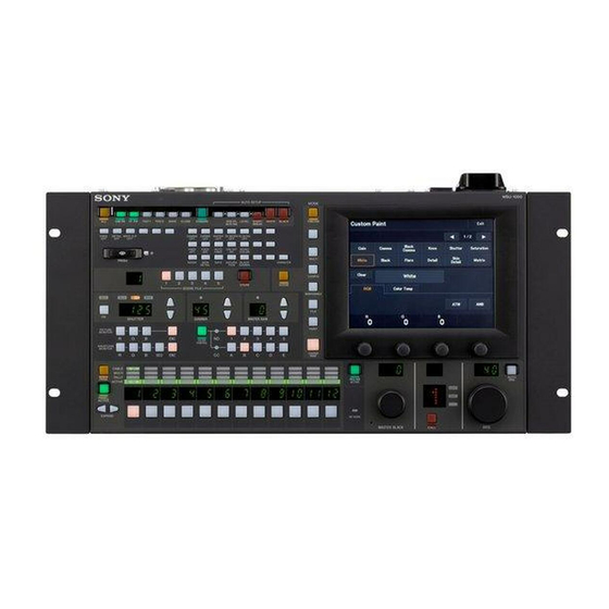
- Page 1 MASTER SETUP UNIT MSU-1000 MSU-1500 OPERATION MANUAL [English] 1st Edition (Revised 6)
-
Page 2: Table Of Contents
About “Memory Stick Duo” ........68 Table of Contents Inserting a “Memory Stick Duo”........68 Protecting Saved Data ...........68 Precautions ..............68 Specifications ............69 Precautions..............3 Overview ..............4 Features................4 Examples of System Configurations ........ 6 Supported devices ............8 Operating Cameras ............8 Names and Functions of Parts .........9 Operation Panel............... -
Page 3: Precautions
Precautions Note on faulty pixels on the LCD panel The LCD panel fitted to this unit is manufactured with high precision technology, giving a functioning pixel ratio of at least 99.99%. Thus a very small proportion of pixels may be “stuck,” either always off (black), always on (red, green, or blue), or flashing. -
Page 4: Overview
2) 3) temperature of the specified camera system. control panels can centrally control multiple camera systems. • The MSU-1000 is has a horizontally long shape and is provided with various direct switches to make quick configuration possible. • The MSU-1500 has a compact vertically long shape and is of the same height as the RCP-1500/1501/1530. - Page 5 You can also transfer scene files and reference files from a camera or “Memory Stick Duo” to multiple cameras. 1) If a system includes control panels other than the MSU-1000 series and RCP-1000 series control panels, the maximum number of cameras that can be controlled will be reduced.
-
Page 6: Examples Of System Configurations
Camera heads CCU (1 to 6) VCS-700 CNU-700 RCP (1 to 6) MSU-1000/1500 CCU/ REMOTE CCA-5 cable • The maximum cable length from a CCU to an RCP is 200 m (approx. 656 ft.). • Up to six systems can be connected to a CNU-700 as standard. In such a case, connect one MSU and one VCS. - Page 7 Connection example for MCS mode Camera heads PoE compatible switching hub MSU-1000/1500 LAN straight cable (category 5 or above) • In MCS mode, be sure to set one of the multiple MSUs as the master. Not to turn off the power or disconnect the cable of the master MSU during operation.
-
Page 8: Supported Devices
Supported devices Operating Cameras This unit supports connection to the following devices. Camera control permissions (panel active, • BVP-E30 series IRIS/MB active, and PARA) • CCU-590/790 series By combining an MSU and RCP, you can operate one camera • HDC1000(R)/1500(R)/3300(R) series device from multiple control panels, and multiple cameras from •... -
Page 9: Names And Functions Of Parts
Names and Functions of Parts Operation Panel MSU-1000 Camera/panel control block (page 10) Menu operation block (page 12) MSU-1000 AUTO SETUP MODE CAM PW VF PW TEST1 TEST2 BARS CLOSE STANDARD SKIN DTL LEVEL START/ WHITE BLACK FUNCTION AUTO HUE... - Page 10 Camera/panel control block MSU-1000 MSU-1500 MSU-1500 AUTO SETUP CAM PW VF PW TEST1 TEST2 BARS CLOSE STANDARD SKIN DTL LEVEL START/ WHITE BLACK AUTO HUE BREAK KNEE DETAIL 5600K SKIN GATE SATURA BLACK CHARACTER MODE DETAIL TION GAMMA SCENE FILES...
- Page 11 8 buttons and 3 buttons are spare by default. Button Description KNEE OFF Knee compensation function In the case of MSU-1000, the following switch functions are DETAIL OFF Detail function assigned to 19 buttons and 9 buttons are spare by default. 5600K...
- Page 12 ON/OFF CNU character display. For details on for what kind of image output characters are displayed, refer to the operation manual of the device of the connection destination. Menu operation block MSU-1000 MSU-1500 MODE MSU-1500 AUTO SETUP CAM PW...
- Page 13 Function control block MSU-1000 MSU-1500 MSU-1500 AUTO SETUP CAM PW VF PW TEST1 TEST2 BARS CLOSE STANDARD SKIN DTL LEVEL START/ WHITE BLACK AUTO HUE BREAK KNEE DETAIL 5600K SKIN GATE SATURA BLACK CHARACTER MODE DETAIL TION GAMMA PRO Duo...
- Page 14 3 Shutter control block (MSU-1000 only) 5 GAMMA (gamma selection) buttons and display window (MSU-1000 only) SHUTTER a Gamma display window This window is for displaying the setting value (decimal value) a DEG indicator of the step gamma. This indicator is lit when the shutter indication is an angle b Standard value indicator value.
- Page 15 This window is for indicating the setting value of the master gain. b Standard value indicator (MSU-1000 only) This lights when the standard value is set in the Standard Indication menu. It light in green for a standard state, and amber for a non-standard state.
- Page 16 Camera selection block MSU-1000 CABLE MULTI TALLY PARA MSU-1000 AUTO SETUP MODE ACTIVE CAM PW VF PW TEST1 TEST2 BARS CLOSE STANDARD AUTO HUE SKIN DTL LEVEL START/ WHITE BLACK FUNCTION BREAK KNEE DETAIL WHITE CLIP GAMMA CHROMA MATRIX SD MATRIX...
- Page 17 When the control panel is connected to a CNU, the maximum number is set automatically. Connect the control panel to the camera network system. Connected to a CHU/CCU device in the camera network system. Adjustment block MSU-1000 MSU-1500 MSU-1000 AUTO SETUP MODE MSU-1500 AUTO SETUP D.EXT...
-
Page 18: Connector Panel
You can select the call sound. When both red and green tally signals are simultaneously sent, the left half of the background lights in red, and the right half lights in green. Connector Panel MSU-1000 MSU-1500 REMOTE CCU/CNU REMOTE DC IN 10.5-17V... -
Page 19: Installation
2 Use the adjustment knobs on the left to set your region and set the hour offset from Greenwich Standard Installation Time. [Set] 3 Press For details on menu operation, see “Menus” (page 35). Set the date. [Date] 1 Press and highlight Setting the Clock Date/Time Exit... -
Page 20: To Set To Legacy Mode
To set to LEGACY mode MSU Config Engineer Mode Exit Set the control panel to LEGACY mode when connecting without using a LAN cable. When the control panel is connected, for example, to a multi-camera system with a CNU- Display Customize Mode Date/Time... -
Page 21: To Set To Bridge Mode
To set to BRIDGE mode Set the connection mode. [Edit] Set the control panel to BRIDGE mode when connecting the 1 Press control panel and a camera device on a LAN on a one-to-one The Bridge Mode Set screen appears. basis. -
Page 22: To Set To Multi-Camera System (Mcs) Mode
[CNS] 2 Set the IP address, Subnet mask, and Default Press Gateway. The CNS screen appears. Press the corresponding input field, and then use the numeric keypad on the screen to enter the information. Camera Network System Engineer Mode Exit [Set] 3 Press [Exit]... -
Page 23: Settings
[Exit] Press Settings The Network screen reappears. Set the TCP/IP. [TCP/IP] 1 Press For details on menu operation, see “Menus” (page 35). The TCP/IP screen appears. TCP/IP Engineer Mode Exit Setting the User Interface IP Address To set the sounds The control panel plays a sound when call signals are Subnet Mask received, and when the panel is operated. -
Page 24: To Set The Brightness Of The Leds
To set the brightness of the LEDs Select the type of sound to set. Four types of sound can be set. Press the tab to display You can adjust the brightness of the operation buttons and tally the setting screen of the desired sound, and then set each display window on the control panel. -
Page 25: To Adjust The Lcd
[EL] To adjust the LCD Press and highlight The EL submenu appears. You can adjust the brightness of the LCD of the menu operation block. Display/Sound Exit Display the MSU Config screen. (page 35) Touch Sound Panel MSU Config Exit Clear Display Mode... -
Page 26: To Perform Rpn Correction
[Screen Saver] [RPN] Press Press The Screen Saver screen appears. The RPN Correction screen appears. Screen Saver RPN Correction Exit Engineer Mode Exit Screen Saver Preview Enter Wait Time 3 min Type Cursor Indication H Cursor V Cursor Cursor Vertical Drawing H Cursor V Cursor 157ev... -
Page 27: Setting Security Restrictions
[Enter] Press Setting Security Restrictions The cursor position is set, and the RPN Correction screen changes to the following. To set the security level RPN Correction Engineer Mode Exit You can restrict the control functions of the control panel if necessary. -
Page 28: To Protect Operations With A Security Code
Code Delete Turn on the control panel while holding down the PARA button, PANEL ACTIVE button, and camera selection button 1. MSU-1000 [Code Enable] Press to light the button. Security code protection is enabled. CABLE... - Page 29 [Engineer Mode] Enter engineer mode. (page 35) Press The numeric keypad and security code (Code No.) input Security Engineer Mode Exit field appear. Security Exit Page Item Code Permission Permission Change Engineer Mode Page Item Code Permission Permission Change New Code No : MSU ALL Engineer Preset...
-
Page 30: Operation Settings
PIX/WF Synchro Operation Settings Turn ON/OFF linking of output from the PIX2 OUTPUT and WF2 OUTPUT connectors to RGB switching on the To set the PIX/WF operations adjustment display. [ON] • Press to light the button and switch to linking of You can set the following operations for PIX/WF output. -
Page 31: Customization
[Mode] Press Display the MSU Config screen. (page 35) The Mode screen appears. MSU Config Engineer Mode Exit MSU Mode Engineer Mode Exit Display Customize Mode Date/Time Network Information /Sound Screen Matrix Extend Camera PIX/WF Saver Gate CALL Select Security Battery Alarm Backup... -
Page 32: To Set The Custom Paint Menu
Enter engineer mode. (page 35) SW Customize Engineer Mode Exit Press the CONFIG button. The menu closes and the control panel remains in GATE engineer mode. NO ASSIGN Enter 5600K AUTO KNEE SKIN DETAIL Display the MSU Config screen. (page 35) GATE BLACK GAMMA KNEE APERTURE... -
Page 33: Saving And Initializing Settings
[Delete] To add a paint menu item to the custom paint menu Press The page is deleted. Press and highlight the place to insert the paint menu To reset the custom paint menu to the default item in the custom paint menu registration area. settings Turn the adjustment knob on the far left to select the [Default All]... -
Page 34: To Initialize The Settings
[Enter] Confirm the file number, and press Backup Engineer Mode Exit The settings are saved to the “Memory Stick Duo.” [File ID] Press to set or change the File ID in the file. Menu Panel Network Customize Customize Config Config When software keyboard is displayed, enter a File ID, and [Enter] press... -
Page 35: Menus
Set or adjust the item. Menus • Turn the knob (or press the button) corresponding to the setting or adjustment item (parameter) to adjust the item to the desired value (select the desired setting). • If a message appears, perform the operation in [OK] accordance with the message, and then press Menu Operations... - Page 36 Press the CONFIG button. The Configuration screen appears. Configuration Exit Camera Multi BPU Multi Assignment Format Format [MSU] Press The MSU Config screen appears. MSU Config Exit Display Mode Date/Time Information /Sound Security [Security] Press The Security screen appears. Security Exit Engineer Mode...
-
Page 37: Menu Tree
Menu Tree Menus... - Page 38 Multi Mode Master/Subordinate Screen Saver Character PIX/VF Function Matrix Gate Optical Level Extend Call PIX/WF Camera Select Date/Time Date Time Time Zone Network Network Info LAN I/F TCP/IP Information Version Network Info Security Page Permission Item Permission MSU ALL Preset Engineer Mode Backup Menu Customize...
-
Page 39: Paint Menu
Paint Menu Screen display example (when “Knee” is selected in the Paint menu) Paint Exit Gamma Black Gamma Knee Shutter Saturation /Knee Gamma Skin White Black Flare Matrix Gamma Detail Knee Clear Knee Point Knee Slope Auto knee Master a Press this to return to the previous menu screen. g Press this to light the button in red and display a red frame around items that can be cleared. - Page 40 Menu items Paint menu Switch Control item Description Menu Submenu White Corrects the color reproduction of the camera to match the color temperature of the light source shining on the subject. R/G/B Changes the sensitivity of each primary color (R, G, and B) and corrects the color temperature.
- Page 41 Paint menu Switch Control item Description Menu Submenu Level Dep Contour correction is not applied to the dark parts and S/N sensitivity is increased in order to reduce the emphasizing of also the contours of noise by the contour correction function. Adjusting this in the plus direction results in contour correction not being applied up to a brighter level.
- Page 42 Paint menu Switch Control item Description Menu Submenu Zoom Link Turns on/off the function that changes the correction amount for Skin DTL in response to the zoom value of the camera. Skin DTL 2 Sets the second channel of Skin DTL. Level This is the contour correction value within the color area that is set with Phase or Width.
- Page 43 Paint menu Switch Control item Description Menu Submenu Matrix Corrects the color reproduction without changing the white balance. Enables the matrix function. This switch enables the function to be turned ON/OFF simultaneously in accordance with individual matrix settings. User 1/2 Sets the matrix correction factor individually.
- Page 44 Paint menu Switch Control item Description Menu Submenu Gamma Corrects the photoelectric conversion characteristic of the image pickup device to the luminance characteristic of the display. Disables the gamma correction function. Gamma R/G/B Adjusts the correction level of each of R, G, and B. Master Links R, G, and B and adjusts them simultaneously.
- Page 45 Paint menu Switch Control item Description Menu Submenu Shutter Controls the exposure time of the image pickup device. Shutter Selects and sets the shutter mode. Angle Displays the shutter speed as an angle value. Slow Shutter Slow Shutter Shoots with the frequency from the frame frequency of the capture image format (unit: number of frames).
- Page 46 Paint menu Switch Control item Description Menu Submenu Flicker Reduction This function is for super motion. It allows you to reduce flickering on the screen caused by the relationship between temporal fluctuations of the light source and the frame frequency of the camera. Enables the Flicker Reduction function.
-
Page 47: File Menu
File Menu Screen display example (when “Scene” is selected in the File menu, and then “Scene Transfer” is selected) Scene Transfer Exit File ID Delete CAMs CAMs No Cam Date Time 09 / 10 / 10 14 : 30 HDC-1000 09 / 12 / 31 16 : 25 HDC-1000 Enter a Press this to return to the previous menu screen. - Page 48 File menu Control item Function Menu Submenu Auto White Adjusts the auto white. Auto Black Adjusts the auto black. Adjusting Black Shading Adjusts the black shading. White Shading Adjusts the white shading. Black Set Adjusts the black set. Matrix Adjusts the OHB matrix. Custom Matrix Store Registers a Custom Preset Matrix file.
-
Page 49: Maintenance Menu
Maintenance Menu Screen display example (when “Camera” is selected in the Maintenance menu) Camera Exit Camera Exit Black White Black Microphone Black White Black Microphone Shading Shading Matrix Gain Shading Shading Matrix Gain Black Shading Clear Auto B Shading Master a This displays the setting items. - Page 50 Maintenance menu Submenu Switch Control item Description Menu Secondary menu Auto B Shading This is the Auto Black Shading. It automatically adjusts each of the RGB, HV, and SAW/PARA parameters. Auto adjustment may be additionally performed with 2D Black Shading depending on the camera.
- Page 51 Maintenance menu Submenu Switch Control item Description Menu Secondary menu Black Set Makes adjustments so that the black level of each color does not change when the master gain is changed. Black Set R/G/B Adjusts the correction level of each of R, G, and B. This is the Auto Black Balance.
- Page 52 Maintenance menu Submenu Switch Control item Description Menu Secondary menu Lens These are the maintenance items related to the lens. Auto Iris Settings Sets various parameters of the auto iris. Level Sets the convergence level of the auto iris. The higher the value the brighter it becomes.
- Page 53 Maintenance menu Submenu Switch Control item Description Menu Secondary menu 3D Monitor Sets the 3D Monitor output of the CCU. Select Select Left Camera, Right Camera or 3D Monitor for the 3D Monitor output. Mode Sets the display mode during the 3D Monitor output setting. Border Line Sets whether to display the border lines when the 3D Monitor Mode is set to split mode.
- Page 54 Maintenance menu Submenu Switch Control item Description Menu Secondary menu Corrects the signal of the R channel in accordance with the difference between the signals of the R channel and G channel. Corrects the signal of the G channel in accordance with the difference between the signals of the G channel and B channel.
- Page 55 Maintenance menu Submenu Switch Control item Description Menu Secondary menu The maintenance items related to the VCS. Monitor Level Adjusts the Monitor Out. WF Level Adjusts the output level. WF Chroma Adjusts the chroma level. VCS Character Outputs VCS characters. Character Adjusts the character level.
-
Page 56: Config Menu
Config Menu Screen display example (when “Camera” (Mode of Camera Config) is selected in the Config menu) Camera Mode Exit White Setup Mode White Gamma RGB Auto White Shading mode Auto RB Only Level Camera Fan Mode 16:9 Auto1 Auto2 Maximum Minimum Crop... - Page 57 Triax interface Fiber Fiber interface See “MSU menu items” (page 58). Sets the system configuration using the CNU. (For details on the CNU menu, please contact your Sony representative.) RCP Assignment See “To change RCP assignments” (page 63). Multi Format Sets the video format for each CCU output.
- Page 58 Standard Ind Selects the standard state. The LED at the top of the corresponding (MSU-1000 only) indication lights green in the standard state, and amber in the non- standard state. It remains off when not even one standard state is selected.
- Page 59 Menu Secondary Submenu Switch Control Description menu item Touch Sets the operation sound for when a switch on the LCD is pressed. Sound Test Confirms the set operation sound. Touch Sound Disables the operation sound. Volume Adjusts the volume of the operation sound. Sound Selects the type of the operation sound.
- Page 60 Menu Item Option Function Mode Screen Saver Sets the screen saver to display on the LCD. Enables the screen saver function. Preview Displays a preview of the set screen saver. Wait Time Sets the time from when the last operation was performed until when the screen saver is displayed.
- Page 61 Menu Item Option Function Security Page Permission Full Lock Locks all menu screens. View Mode Locks the menu screens. However, the menus can be viewed. Custom Paint Only Enables the menus such as Paint, Maintenance, and File. Item Permission Ref File Enable Enables the operation of reference files.
-
Page 62: To Set The Return Input Settings
To set the return input settings To control the CCU menu [Return Settings] [CCU Menu Control] Select in the CONFIG menu to set the Select in the CONFIG menu to remotely formats of return signals from the CCU. control the menu displayed for image output of the CCU from this control panel. -
Page 63: To Change Rcp Assignments
To change RCP assignments Notes [RCP Assignment] Selecting in the Config menu allows you • You can select only the file number button that has state to change RCP assignments. of RCP assignment saved. • When the file number button is pressed and a changed Note state is reflected in the RCP List, RCP assignment has The following RCP assignment function is only available in... - Page 64 [CLR] Press the button. The confirmation message screen for file clearing is displayed. RCP Assignment Exit Files File No.1 Clear OK? Cancel Camera Cancel Store Reset Camera Panel [OK] Press The saved data of the specified file is cleared, and the file number button will be disabled.
-
Page 65: Multi Menu
Multi Menu Multi Exit Master/ Chara- Subordinate cter a Press this to return to the previous menu screen. Menu items Item Control item Function Master/Subordinate Master Specifies the master function. Subordinate Specifies the subordinate function. All Subordinate Specifies the subordinate function for all of the cameras. All Off Cancels the subordinate specification for all of the cameras. -
Page 66: Function Menu
Function Menu Screen display example Function Function Exit Exit Optical Level PIX/WF Optical Level PIX/WF connecting the normal camera connecting the separate camera When When a Press this to return to the previous menu screen. [PIX/WF] b Press a tab to change to the submenu. The is only displayed for the MSU-1500. -
Page 67: Scene Menu
Scene Menu Screen display example (when connected to the cameras of the 32 scene files) Scene Store/Recall Exit Scene Prev Next Scene Scene Dissolve Store [Dissolve] a Press this to return to the previous menu screen. e When you press to turn it on, the picture changes gradually when the scene file is recalled. -
Page 68: About "Memory Stick Duo
— Very humid or subject to corrosive substances • To prevent data loss, make backups of data frequently. In no event will Sony be liable for any loss of data. Note • Unauthorized recording may be contrary to the provisions of If there is some resistance when you insert it or it does not fit copyright law. -
Page 69: Specifications
5 ° C to 40 ° C (41 ° F to 104 ° F) Operating DC IN 4-pin (1) temperature Supplied accessories Weight MSU-1000: Approx. 4.6 kg (10 lb. 2 oz.) Operation guide (1) MSU-1500: Approx. 3.6 kg (7 lb. 15 oz.) Operation manual (CD-ROM) (1) Optional accessories External dimensions Unit: mm (inches) - Page 70 The material contained in this manual consists of information that is the property of Sony Corporation and is intended solely for use by the purchasers of the equipment described in this manual. Sony Corporation expressly prohibits the duplication of any...
- Page 71 Sony Corporation MSU-1000 (SY) MSU-1500 (SY) 4-169-281-07(1) © 2010...