Table of Contents
Advertisement
Quick Links
Download this manual
See also:
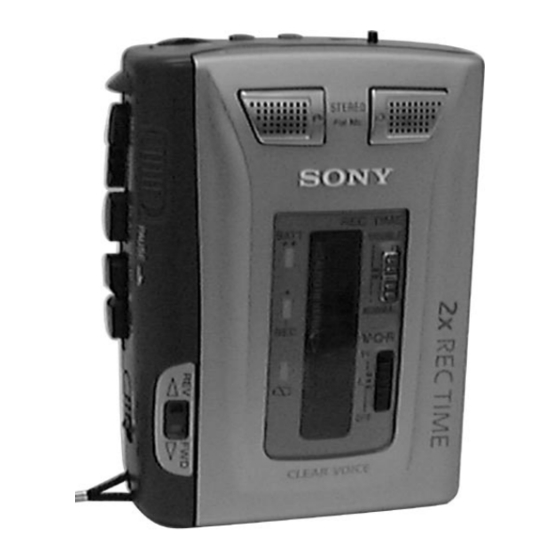
Operating Instructions
SERVICE MANUAL
Ver 1.0 1999. 03
Recording system
4-track 2 channel stereo
Tape speed
4.8 cm/s or 2.4 cm/s
Frequency range
250 – 8,000 Hz using nomal (TYPE1) cassette
(with REC TIME switch at "NORMAL")
Speaker
Approx. 3.6 cm (1
Power output
Speakers
Headphones : 6 mW + 6 mW
Input
Microphone input jack (minijack) sensitivity
0.2 mV for 3 Ω or lower impedance
microphone
2 (headphones) jack (minijack) for
Output
8 – 300 Ω earphone
MICROFILM
SPECIFICATIONS
in.) dia. ×2
7
/
16
: 160 mW + 160 mW
(at 10 % harmonic distortion)
(at 10 % harmonic distortion)
TCS-60DV
Model Name Using Similar Mechanism
Tape Transport Mechanism Type
Variable range of the tape speed
From approx. +25 % to – 15 %
(with REC TIME switch at "NOMAL")
Power requirements 3 V DC batteries AA (R6) ×2/
External DC 3 V power sources
Dimensions (w/h/d)(incl. projecting parts and controls)
Approx. 88.7 × 113.4 × 41.3 mm
× 4
× 1
1
1
(3
/
/
2
2
Mass
Approx. 280 g (9.9 oz)
Design and specifications are subject to change without notice
CASSETTE CORDER
US Model
Canadian Model
AEP Model
E Model
TCM-50DV
MT-50-30
11
/
inches), incl.
16
Advertisement
Table of Contents

Related Manuals for Sony TCS-60DV


Summary of Contents for Sony TCS-60DV
- Page 1 TCS-60DV SERVICE MANUAL US Model Canadian Model Ver 1.0 1999. 03 AEP Model E Model Model Name Using Similar Mechanism TCM-50DV Tape Transport Mechanism Type MT-50-30 SPECIFICATIONS Variable range of the tape speed Recording system 4-track 2 channel stereo Tape speed 4.8 cm/s or 2.4 cm/s...
-
Page 2: Table Of Contents
TABLE OF CONTENTS 1. SERVICE NOTE ······························································· 3 2. GENERAL ·········································································· 4 3. DISASSEMBLY 3-1. Cabinet (rear) Assy, Lid Sub Assy, Cassette ··················· 5 3-2. MAIN Board, Mechanism Deck ····································· 5 3-3. Belt ·················································································· 6 3-4. Head ················································································ 6 3-5. Motor, DC ······································································· 7 3-6. -
Page 3: Service Note
SECTION 1 SERVICE NOTE The TCS-60DV detects rotation of both the supply and take-up side How to remove the Main board (opening the Main board) reels using the PH701 (photo reflector). Because the PH701 is 1) Refer to page 5 “3. Disassembly”. -
Page 4: General
SECTION 2 GENERAL This section is extracted from instruction manual. 1 2 Headphone jack !™ Tape direction indicators 2 MIC (PULG IN POWER) jack !£ SPEAKER (REAR SIDE) 3 VOL knob !¢ TAPE COUNTER switch 4 r REC button !∞ Flat mic 5 p STOP button !§... -
Page 5: Disassembly
SECTION 3 DISASSEMBLY Disassemble the unit in the order as shown below. "Cabinet (rear) assy", "lid sub assy, cassette" Main board, Mechanism deck Belt Head Motor, dc Note : Follow the disassembly procedure in the numerical order given. 3-1. “CABINET (REAR) ASSY”, “LID SUB ASSY, CASSETTE” 9 Lid Sub Assy, Cassette 5 PWB, LED Flexible 8 Screw, ornamental... -
Page 6: Belt
3-3. BELT 1 Belt(motor) 2 Belt(flywheel) 3 Belt(counter) • How to thread the belt Belt(counter) Belt(flywheel) Belt(motor) 3-4. HEAD 1 two screws 2 head, magnetic (REC/PB/ERASE) — 6 —... -
Page 10: Schematic Diagram
TCS-60DV 5-2. SCHEMATIC DIAGRAM • Waveform TP45 REC DOUBLE MODE 10 µsec/div 5 V/div 52 kHz TP45 REC NORMAL MODE 10 µsec/div 10 V/div 52 kHz 5 µsec/div IC303 LX REC 1 V/div Note on Schematic Diagram: • All capacitors are in µF unless otherwise noted. pF: µµF 50 WV or less are not indicated except for electrolytics and tantalums. - Page 11 TCS-60DV 5-3. PRINTED WIRING BOARD – MAIN SECTION – • Semiconductor Location Ref. No. Location D301 D302 B-20 D303 C-23 D304 C-22 D305 E-13 D306 C-20 D307 D308 D701 D702 B-14 IC101 IC201 B-17 IC301 IC303 IC304 B-19 IC305 D-18...
-
Page 12: Ic Block Diagrams
TCS-60DV 5-4. PRINTED WIRING BOARD – LED SECTION – 5-5. IC BLOCK DIAGRAMS • Semiconductor IC501 NJM2072M IC502 MM1251BFBE Location Ref. No. Location D501 D502 D503 INPUT – IC502 GAIN CONT OUTPUT2 Q504 Q505 BOOSTER AMP OUT OUTPUT1 – SIRCUIT... - Page 13 IC301 LA7473V-TLM INT MIC OUTPUT AMP R AMP R AMP R EXT MIC AMP R EXT MIC BIAS EXT MIC AMP L OUTPUT RIPPLE INT MIC AMP L AMP L FILTER AMP L 1 2 3 6 7 8 9 10 11 12 13 14 IC601 LB1877V-TLM...
-
Page 14: Ic Pin Function Discription
5-6. IC PIN FUNCTION DESCRIPTION IC701 TB2004FN-020-ER(SYSTEM CONTROL)/MAIN BOARD Pin No. Pin Name Description – Ground – For generation of system clock (fosc = 3.2 kHz) Reset signal input IN-1 PAUSE ON/OFF by the PAUSE switch and V•O•R switch “L”: ON, “OPEN”: OFF IN-2 Recovery to FWD when opening/closing the cassette lid “L”: ON, “OPEN”: OFF IN-3... -
Page 15: Exploded Views
SECTION 6 EXPLODED VIEWS NOTE: • -XX, -X mean standardized parts, so they may • The mechanical parts with no reference number have some differences from the original one. in the exploded views are not supplied. • Items marked “*” are not stocked since they •... -
Page 16: Main Section-2
6-2. MAIN SECTION-2 SP901 not supplied SP902 MT-50-30 Ref. No. Part No. Description Remarks Ref. No. Part No. Description Remarks 3-704-197-33 SCREW (IB LOCK) X-3377-552-1 CABINET (REAR) ASSY 3-318-382-31 SCREW (1.7 × 3), TAPPING X-3377-632-1 CABINET (FRONT) ASSY 3-032-431-01 KNOB(PAUSE) 3-328-319-01 STRAP, HAND 3-032-432-01 KNOB(DIR) 3-032-441-01 SHEET (PICK) -
Page 17: Mechanism Deck Section-1
6-3. MECHANISM DECK SECTION-1 (MT-50-30) supplied NOTE : Refer to next page. • A supplied HRPE901 supplied not supplied M601 Ref. No. Part No. Description Remarks Ref. No. Part No. Description Remarks 3-925-247-11 BUTTON, FF X-3370-375-1 TABLE ASSY, REEL 3-925-246-11 BUTTON, REW * 118 3-924-535-01 LEVER (FR) 3-925-245-11 BUTTON, PLAY... -
Page 18: Mechanism Deck Section-2
6-4. MECHANISM DECK SECTION-2 (MT-50-30) (included • A) NOTE : Refer to befor page not supplied Ref. No. Part No. Description Remarks Ref. No. Part No. Description Remarks X-3370-373-1 CHASSIS ASSY 3-924-598-01 SPRING (P/S), TORSION * 152 3-924-537-01 LEVER (F/R) 3-924-604-01 SPRING (PLAY), TENSION 3-924-605-01 SPRING (FF), TENSION * 174... -
Page 19: Electrical Parts List
SECTION 7 MAIN ELECTRICAL PARTS LIST NOTE: • Due to standardization, replacements in the • CAPACITORS: • SEMICONDUCTORS parts list may be different from the parts uF: µF In each case, u: µ, for example: specified in the diagrams or the components •... - Page 20 MAIN Ref. No. Part No. Description Remarks Ref. No. Part No. Description Remarks C507 1-107-826-91 CERAMIC CHIP 0.1uF < COIL > C510 1-107-826-91 CERAMIC CHIP 0.1uF C601 1-162-968-11 CERAMIC CHIP 0.0047uF 10% L301 1-412-030-11 INDUCTOR CHIP 22uH C602 1-164-005-11 CERAMIC CHIP 0.47uF L302 1-414-222-11 INDUCTOR...
- Page 21 MAIN Ref. No. Part No. Description Remarks Ref. No. Part No. Description Remarks R122 1-216-801-11 METAL CHIP 1/16W R605 1-216-839-11 METAL CHIP 1/16W R123 1-216-841-11 METAL CHIP 1/16W R606 1-216-831-11 METAL CHIP 6.8K 1/16W R124 1-216-841-11 METAL CHIP 1/16W R607 1-216-809-11 METAL CHIP 1/16W R125...
- Page 22 TCS-60DV Ref. No. Part No. Description Remarks Ref. No. Part No. Description Remarks < DIODE > MISCELLANEOUS ************** D501 8-719-059-96 DIODE SML-210LT-T86(POWER) 1-657-172-11 PC BOARD, MOTOR FLEXIBLE D502 8-719-059-96 DIODE SML-210LT-T86(REC) 1-548-582-11 COUNTER, TAPE (SMALL TYPE) D503 8-719-057-99 DIODE SML-211YT-T86 (BATT CHECK)