Table of Contents
Advertisement
Quick Links
Operation Manual
For Menu Screens
Thank you for purchasing our product.
This manual provides important information about safe and proper operations
of this Switching Hub.
Please read the "Important Safety Instructions" on pages 2 to 4.
Any problems or damage resulting from disassembly of this Switching Hub by
customers are not covered by the warranty.
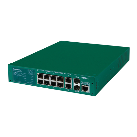
Switch-M8ePWR
Model Number:
PN27089KA
Advertisement
Table of Contents

Related Manuals for Panasonic Switch-M8ePWR PN27089KA


Summary of Contents for Panasonic Switch-M8ePWR PN27089KA
- Page 1 Switch-M8ePWR Operation Manual For Menu Screens PN27089KA Model Number: Thank you for purchasing our product. This manual provides important information about safe and proper operations of this Switching Hub. Please read the "Important Safety Instructions" on pages 2 to 4. ...
- Page 2 Important Safety Instructions This chapter contains important safety instructions for preventing bodily injury and/or property damage. You are required to follow them. Severity of bodily injury and/or property damage, which could result from incorrect use of the Switching Hub, are explained below. This symbol indicates a potential hazard that could WARNING result in serious injury or death.
- Page 3 WARNING Do not install this Switching Hub at the location with continuous vibration or strong shock, or at the unstable location Deviation could lead to injury and/or equipment failure. Do not install any module other than our optional SFP module to SFP extension slot.
- Page 4 CAUTION Handle the Switching Hub carefully so that fingers or hands may not be damaged by twisted pair port, SFP extension slot, console port, or power cord hook block. Important Requests on Protection from Lightning Strike If you connect a network camera, a wireless access point, or other devices that ...
-
Page 5: Basic Instructions For The Use Of This Product
Basic Instructions for the Use of This Product For inspection and/or repair, consult the retailer. Use commercial power supply from a wall socket, which is close and easily accessible to this Switching Hub. Unplug the power cord when installing or moving this Switching Hub. ... - Page 6 When stacking Switching Hubs, leave a minimum of 20 mm space between them. 1. Panasonic will not be liable for any damage resulting from the operation not in accordance with this document or the loss of communications, which may or may not be caused by failure and/or malfunction of this device.
-
Page 7: Table Of Contents
Table of Contents Basic Instructions for the Use of This Product ............ 5 1. Product Outline ..................11 1.1. Features ....................11 1.2. Accessories ..................13 1.3. Optional Accessories ................13 1.4. Part Names and Functions ..............14 1.5. LED Behavior ..................17 1.5.1. - Page 8 4.4. Main Menu ..................36 4.5. General Information Menu ..............37 4.6. Basic Switch Configuration ..............39 4.6.1. System Administration Configuration ..........40 4.6.2. System IP Address Configuration ............. 41 4.6.3. SNMP Configuration ............... 43 4.6.3.a. SNMP Management Configuration ..........44 4.6.3.b.
- Page 9 4.7.2.b. Trunk Configuration Menu ............99 4.7.2.c. Set Port Priority for LACP ............102 4.7.2.d. LACP Group Status ..............104 4.7.3. Port Monitoring Configuration ............106 4.7.4. Rapid Spanning Tree Configuration ..........108 4.7.4.a. Basic Port Configuration ............112 4.7.4.b. Advanced Port Configuration ..........114 4.7.4.c.
- Page 10 4.9.7. Watch Dog Timer Menu ..............179 4.10. Save Configuration to Flash .............. 180 4.11. Command Line Interface (CLI) ............182 4.12. Logout ..................... 183 Appendix A. Specifications ................184 Appendix B. Procedures for Console Port Configuration Using Windows HyperTerminal ..................... 187 Appendix C.
-
Page 11: Product Outline
Switch-M8ePWR is a Layer-2 Ethernet Switching Hub with management function having 8 ports of 10BASE-T/100BASE-TX supporting IEEE802.3af PoE power supply function, and 2 ports of 10BASE-T/100BASE-TX/1000BASE-T and SFP extension slot, one of which is selectable. All are twisted pair ports corresponding to auto negotiation. - Page 12 Hub from the SNMP manager. (For details, refer to Appendix A.) Spanning Tree Protocol is supported, allowing to build a redundant system. Ring Protocol is supported, allowing to build a redundant system in ring configuration. VLAN function allows free grouping of up to 256 VLANs. ...
-
Page 13: Accessories
Please be sure to confirm the content. Please contact our distributor if any of the contents are insufficient. Quantity Installation Guide CD-ROM (PDF version of Operating Instuctions) Rubber foot (magnet built-in) Screws (for fixing rubber foot) Power cord (CEE7/7)(*) ... -
Page 14: Part Names And Functions
Power cord hook block Back panel MAC address label Power port Serial number label Front panel SFP extension slot PoE power supply supported Console port 10/100BASE-TX port 10/100/1000BASE-T port Magnified Status/ECO mode LED PoE mode LED GIGA mode LED LED DISPLAY CHANGE Speed mode LED BUTTON Duplex mode LED... - Page 15 Power port Connect the supplied power cord into the port and connect the other end into an electric outlet. Power cord hook block Hooking the supplied power cord on the block makes the cord less likely to be unplugged from the power port.
- Page 16 Use our optional RJ45 D-sub 9 pin console cable (PN72001) for connection. LED display change button Used to change the LED display mode settings. For detailed display information and behavior on each LED display mode, refer to 1.5. The button operation also allows to configure the LED base mode and loop detection function (Enable/Disable).
-
Page 17: Led Behavior
. LED Behavior When power is supplied, all the LEDs are turned ON. Then, POWER LED (Power) lights in green, STATUS LED (Status/ECO mode) light in orange, and self-diagnosis of hardware is executed. On completion of self-diagnosis, POWER LED (Power), STATUS/ECO LED (Status/ECO mode), TEMP LED (Temperature sensor), and FAN LED (Fan sensor) light in green, and the Switching Hub starts operation as a Switching Hub. - Page 18 Behavior Description Temperature LED Green Light Within the threshold setting of the internal (TEMP) temperature sensor. Orange Blink Exceeding the threshold setting of the internal temperature sensor. (For details, refer to 4.6.3.c.) Fan LED Green Light The fan is operating normally. (FAN) Orange Blink Fan error.
- Page 19 Port LEDs According to the switch of the "Port LED display mode" described in the previous section, the port LED display on each port changes as follows: Port LEDs Display mode Behavior Description Left STATUS/ECO Green Light Link is established. Green Blink Transmitting and receiving data.
-
Page 20: Loop Detection Function
Port LED (Right) Port LED (Left) Fig. 1-5 Port LEDs When a port causes a loop, the corresponding LED lights up in orange. In this case, the port is automatically blocked (Default setting: 60 seconds) to prevent a loop. If the loop is not recovered, the port will be blocked again. -
Page 21: Operation Overview Of Poe Power Supply Function
Ports 1 to 8 can support IEEE802.3af PoE power supply. The Switching Hub can supply power up to 15.4 W per port, and up to 124 W in total. Power supply operation when the PoE limit LED is blinking orange (the whole unit is overloaded) When the whole unit is overloaded because power request exceeds the limit, you can verify a port that stopped supplying power by switching the LED... -
Page 22: Led Display Change Button
You can select either of the two LED display modes in this Switching Hub: "Status mode" and "ECO mode." The mode after system boot is called "Base mode." By pressing and holding the LED DISPLAY CHANGE BUTTON for more than 3 seconds, you can switch the Base mode. -
Page 23: Installation
Take out the supplied 4 rubber feet (with built-in magnets), and place the Switching Hub upside down. Fix the 4 rubber feet firmly to the Switching Hub using 4 screws (for magnetic mount). Rubber foot (magnet built-in) Fig. 2 1 Switch-M8ePWR bottom face Note: Do not install the Switching Hub in such places as the unstable location, where there is strong vibration or shock, or where a person may walk... -
Page 24: Mounting To Rack (Option)
Use the two 19-inch rack mount brackets and eight screws (for fixing the mount brackets to the Switching Hub) included in the PN71051 optional brackets to fix the mount brackets to the four holes on each side of the Switching Hub. Then securely install the Switching Hub on the rack using the four screws (for a 19-inch rack mount) included in the PN71051 brackets or screws supplied with the rack. - Page 25 Screw holes for fixing the 19-inch rack mount brackets Fig. 2-2 Installing in rack...
-
Page 26: Mounting To Wall (Option)
Use the two wall mount brackets and eight screws (for fixing the wall mount brackets to the Switching Hub) included in the PN71053 optional brackets to fix the mount brackets to the four holes on each side of the Switching Hub. Attach the four rubber feet supplied with the Switching Hub to the recesses at the four corners of the bottom surface of the Switching Hub. -
Page 27: Connection
Connection Cable Use a CAT5E-compliant straight cable (twisted pair) with 8P8C RJ45 modular plugs. Network Configuration 100m or shorter 100m or 100m or shorter shorter Fig. 3-1 Connection example The length of the cable connecting this Switching Hub and a device must be 100 m or shorter. -
Page 28: Connecting A Sfp Extension Slot
1000BASE-SX: 550 m or shorter / 1000BASE-LX: 10 km or shorter 100 m or 100 m or shorter shorter Fig. 3-2 Optical fiber cable connection example Plugging a SFP module (optional) into a SFP extension slot enables an optical fiber connection. The SFP extension port shares the port with the twisted pair port. -
Page 29: Connecting To Power
Connect the supplied power cord to the power port of this Switching Hub and connect the power plug into an electric outlet. The switch operates on AC 100 - 240 V (50/60 Hz). This Switching Hub does not have a power switch. Plugging the power cord turns on this Switching Hub's power and it starts operating. -
Page 30: Configuration
Upon power ON, this Switching Hub starts working as a Switching Hub. To use the SNMP functions and other functions, you need to configure the Switching Hub by using the console, Telnet, or SSH. In this chapter, the configuration of this Switching Hub is explained in detail. Note: To access this Switching Hub via Telnet or SSH, this Switching Hub must have an IP address. -
Page 31: Login
Upon connecting, a login window, similar to Fig. 4-2-1, is displayed. If no similar window is displayed, make sure the transmission mode of console is correct or hit the enter key. If you access the Switching Hub via console, the screen displays as shown in Fig. - Page 32 ============================================================================== PN27089K/PN27089KA Remote Management System Version x.x.x.xx MAC Address: xx:xx:xx:xx:xx:xx ============================================================================== Login Menu Login: Fig. 4-2-2 Login screen (Telnet) On the login screen, similar to Fig. 4-2-1 or Fig. 4-2-2, enter the login name. The Switching Hub's default login name is set to "manager." Enter "manager" and press the Return key.
- Page 33 ============================================================================== PN27089K/PN27089KA Local Management System Version x.x.x.xx MAC Address: xx:xx:xx:xx:xx:xx ============================================================================== Login Menu Login: manager Password: ******* Fig. 4-2-3 Entering password Both the login name and password can be changed. For the detailed change procedure, refer to 4.6.7. Note: When entered, the password is displayed in asterisks(*). Note: Up to four users for Telnet or up to two users for SSH can access the Switching Hub concurrently.
-
Page 34: Basic Operations On The Screen
The console screen of the Switching Hub is organized as follows: 1. Title 2. Parent menu name 3. Current menu name PN27089K/PN27089KA Local Management System Basic Switch Configuration -> System Admin. Configuration Menu Description: Switch-M8ePWR Object ID: 1.3.6.1.4.1.396.5.4.2.16 Name: 4. Configuration Location: Contact: -------------------------------- <COMMAND>... - Page 35 Screen Description Title The title of this screen. Displays "Local Management System" while being accessed via console. Displays "Remote Management System" while being accessed via Telnet. Previous menu Displays the name of the parent menu. Entering the "Q" command name opens the parent menu screen.
-
Page 36: Main Menu
After the login process, the main menu, similar to Fig. 4-4-1, appears. This Switching Hub has a main menu and multiple sub-menus. These menus has a tree structure, with the main menu as its root. To move to a sub-menu, enter a command letter. -
Page 37: General Information Menu
Quit Logouts and returns to the login screen. On the Main Menu, pressing "G" opens the General Information Menu, as shown in Fig. 4-5-1. This screen displays this Switching Hub's basic information. You cannot edit shown information on this screen. PN27089K/PN27089KA Local Management System Main Menu ->... - Page 38 Screen Description System up for: Displays the cumulative time since the power on of this Switching Hub. Boot / Runtime Displays this Switching Hub's firmware version. Code Version: The left side displays the Boot Code and the right side displays the Runtime Code.
-
Page 39: Basic Switch Configuration
On the Main Menu, pressing "B" opens the Basic Switch Configuration Menu, as shown in Fig. 4-6-1. On this screen, you can configure the basic configuration settings, such as IP address, SNMP, and ports. PN27089K/PN27089KA Local Management System Main Menu -> Basic Switch Configuration Menu System [A]dministration Configuration System [I]P Configuration S[N]MP Configuration... -
Page 40: System Administration Configuration
On the Basic Switch Configuration Menu, pressing "A" opens the System Administration Configuration Menu, as shown in Fig. 4-6-2. On this screen, you can set administrative information, such as device name. PN27089K/PN27089KA Local Management System Basic Switch Configuration -> System Admin. Configuration Menu Description: Switch-M8ePWR Object ID: 1.3.6.1.4.1.396.5.4.2.16... -
Page 41: System Ip Address Configuration
On the Basic Switch Configuration Menu, pressing "I" opens the System IP Configuration Menu, as shown in Fig. 4-6-3. On this screen, you can set IP-address-related settings for this Switching Hub. PN27089K/PN27089KA Local Management System Basic Switch Configuration -> System IP Configuration Menu MAC Address: xx:xx:xx:xx:xx:xx IP Address:... - Page 42 Available commands are listed below. Set/edit the IP address. Press "I." The command prompt changes to "Enter IP address>." Enter an IP address for the Switching Hub. M Set/edit the subnet mask. Press "M." The command prompt changes to "Enter subnet mask>." Enter a subnet mask for the Switching Hub.
-
Page 43: Snmp Configuration
On the Basic Switch Configuration Menu, pressing "N" opens the SNMP Configuration Menu, as shown in Fig. 4-6-4. On this screen, you can configure the SNMP agent settings. PN27089K/PN27089KA Local Management System Basic Switch Configuration -> SNMP Configuration Menu SNMP [M]anagement Configuration SNMP [T]rap Receiver Configuration [Q]uit to previous menu Command>... -
Page 44: Snmp Management Configuration
4.6.3.a. SNMP Management Configuration On the SNMP Configuration Menu, pressing "M" opens the SNMP Management Configuration Menu, as shown in Fig. 4-6-5. On this screen, you can configure the SNMP manager settings. PN27089K/PN27089KA Local Management System SNMP Configuration -> SNMP Management Configuration Menu SNMP Manager List: Status Privilege... - Page 45 Available commands are listed below. Set the SNMP manager status. Press "S." The command prompt changes to "Enter manager entry number>." Enter an SNMP manager entry number to change the setting. Then, the command prompt changes to "Enable or Disable SNMP manger (E/D)>." Press "E" to enable the SNMP manager.
-
Page 46: Snmp Trap Receiver Configuration
4.6.3.b. SNMP Trap Receiver Configuration On the SNMP Configuration Menu screen, pressing "T" opens the SNMP Trap Receiver Configuration Menu screen, as shown in Fig. 4-6-6. On this screen, you can set the SNMP Trap settings. PN27089K/PN27089KA Local Management System SNMP Configuration ->... - Page 47 Available commands are listed below. Enable/disable the trap receiver. Press "S." The command prompt changes to "Enter manager entry number>." Enter an entry number for the trap receiver to change the setting. Then, the command prompt changes to "Enable or Disable Trap Receiver (E/D)>." Press "E" to enable the TRAP receiver.
-
Page 48: Enable/Disable Individual Trap Menu
4.6.3.c. Enable/Disable Individual Trap Menu On the SNMP Trap Receiver Configuration Menu screen, pressing "d" opens the Enable/Disable Individual Trap Menu screen, as shown in Fig. 4-6-7. On this screen, you can set the trap sending settings. PN27089K/PN27089KA Local Management System SNMP Trap Receiver Configuration ->... - Page 49 Screen Description SNMP Displays the trap sending settings for an SNMP authentication failure. Authentication Enabled Enables the trap sending. Failure: Disabled Disables the trap sending. (Factory default setting) Enabled Link Displays the port number to which a trap is sent, when its link status Up/Down Port: changes.
- Page 50 Available commands are listed below. Enable/disable the trap sending when the link status changes. Press "A." The command prompt changes to "Enable or Disable SNMP Authentication trap (E/D)>." Press "E" to enable the trap sending. Press "D" to disable it. Add a port to which the trap is sent when its link status changes.
-
Page 51: Port Configuration Basic
On the Basic Switch Configuration Menu, pressing "p" opens the Port Configuration Basic Menu, as shown in Fig. 4-6-8. On this screen, you can configure port status display settings and port settings. PN27089K/PN27089KA Local Management System Basic Switch Configuration -> Port Configuration Basic Menu Port Trunk Type Admin... - Page 52 Screen Description Port Displays the port number. Trunk Displays the group number for a trunked port. Type Displays the port type. 100TX The port type is 10/100BASE-TX. 1000T The port type is 10/100/1000BASE-T. 1000X The port type is 1000BASE-X (SFP port). Admin Displays the current port status.
- Page 53 Available commands are listed below. Enable/disable a port. Press "A." The command prompt changes to "Select port number to be changed>." Enter a port number to change the setting. To configure all ports at once, enter "0" as the port number. Then, the command prompt changes to "Enable or Disable port # (E/D)>."...
-
Page 54: Port Configuration Extend
On the Basic Switch Configuration Menu, pressing "e" opens the Port Configuration Extend Menu, as shown in Fig. 4-6-9. On this screen, you can configure port status display settings and port settings. PN27089K/PN27089KA Local Management System Basic Switch Configuration -> Port Configuration Extend Menu Port Trunk Type Link... - Page 55 Screen Description Port Displays the port number. Trunk Displays the group number for a trunked port. Type Displays the port type. 100TX The port type is 10/100BASE-TX. 1000T The port type is 10/100/1000BASE-T. 1000X The port type is SFP extension port. Link Displays the current link status.
-
Page 56: Port Configuration Power Saving
The MNO series power saving mode detects the connection status automatically and saves power consumption to minimum. This Switching Hub supports two modes: "Half mode" to prioritize connection with other devices and "Full mode" to save more power consumption. On the Basic Switch Configuration Menu, pressing "o" opens the Port Configuration Power Saving Menu, as shown in Fig. - Page 57 Screen Description Port Displays the port number. Link Displays the current link status. A link has been established successfully. Down A link has not been established. Trunk Displays the group number for a trunked port. Type Displays the port type. 100TX The port type is 10/100BASE-TX.
-
Page 58: System Security Configuration
On the Basic Switch Configuration Menu, pressing "S" opens the System Security Configuration Menu, as shown in Fig. 4-6-11. On this screen, you can configure the various settings for accessing this Switching Hub for configuration and management. PN27089K/PN27089KA Local Management System Basic Switch Configuration ->... - Page 59 Access is disabled. IP Setup Displays the access settings for the IP address configuration software, Interface: bundled with the Panasonic network cameras. 'Enabled' is the factory default setting. * For instructions, refer to Appendix C. Enabled: Access is enabled. Disabled: Access is disabled.
- Page 60 Press "G" to move to the Syslog Transmission Configuration page. For configuration details, refer to the next section (4.6.7.c). Configure the access settings for the IP address configuration software, bundled with the Panasonic network cameras. Press "I." The command prompt changes to "Enable or Disable IP setup interface (E/D)>."...
- Page 61 Configure the location to check the login username and password. Press "O." The command prompt changes to "Enter manager entry number>." Press "1" to change the first location to check. Press "2" to change the second location to check. Then, The command prompt changes to "Select the login method." Press "L" to use the username and password set for this Switching Hub.
-
Page 62: Telnet Access Limitation Configuration
4.6.7.a. Telnet Access Limitation Configuration On the System Security Configuration Menu, pressing "A" opens the Telnet Access Limitation screen, as shown in Fig. 4-6-12. In this screen, you can configure limitation of equipment accessing to this Switching Hub via Telnet. PN27089K/PN27089KA Local Management System System Security Configuration ->... - Page 63 Available commands are listed below. Set Enable/Disable of access limitation via Telnet. Set access limitation from Telnet to Enable. Set access limitation from Telnet to Disable. Set an IP address to be permitted. Five ranges can be set up. Press "A." The command prompt changes to "Enter IP address entry number>." Enter an IP address entry number between 1 and 5.
-
Page 64: Radius Configuration
4.6.7.b. RADIUS Configuration On the System Security Configuration Menu, pressing "R" opens the RADIUS Configuration Page screen, as shown in Fig. 4-6-13. In this screen, you can configure accessing to RADIUS server that is used in IEEE802.1X authentication. PN27089K/PN27089KA Local Management System System Security Configuration ->... - Page 65 Available commands are listed below. Set the NAS ID (NAS Identifier). Press "I." The command prompt changes to "Enter NAS ID>." Enter NAS ID in 16 characters or less. Set an IP address of RADIUS server. Press "A." The command prompt changes to "Enter IP Address for RADIUS server>." Enter an IP address.
-
Page 66: Syslog Transmission Configuration
4.6.7.c. Syslog Transmission Configuration On the System Security Configuration Menu, pressing "G" opens the Syslog Transmission Configuration Page screen, as shown in Fig. 4-6-14. In this screen, you can set Syslog server information to send a system log. PN27089K/PN27089KA Local Management System System Security Configuration ->... - Page 67 Available commands are listed below. Set a status of Syslog Transmission. Press "S." The command prompt changes to "Enter manager entry number>." Enter No. to change the setting. Then, the command prompt changes to "Enable or Disable Server (E/D)>." Enter "E" to enable, or "D" to disable the server. Set Facility.
-
Page 68: Ssh Server Configuration
4.6.7.d. SSH Server Configuration On the System Security Configuration Menu, pressing "H" opens the SSH Server Configuration screen, as shown in Fig. 4-6-15. On this screen, you can set SSH server. PN27089K/PN27089KA Local Management System Basic Switch Configuration -> SSH Server Configuration SSH UI Idle Timeout: 60 Min. - Page 69 Available commands are listed below. Create a SSH server key. Press "G" to create the SSH server key. Configure the SSH access settings. Press "H." The command prompt changes to "Enable or Disable SSH server(E/D)>." Enter "E" to enable the access. Enter "D" to disable the access. Configure the idle timeout settings for automatically terminating a SSH-connected session if no input is made.
-
Page 70: Led Base Mode Configuration
4.6.7.e. LED Base Mode Configuration On the System Security Configuration Menu, pressing "B" opens the LED Base Mode Configuration screen, as shown in Fig. 4-6-16. On this screen, you can set the LED base mode settings. PN27089K/PN27089KA Local Management System System Security Configuration ->... - Page 71 Available commands are listed below. Change the current LED base mode. Press "B." The command prompt changes to "Select LED Base Mode (S/E)>." Press "S" to change the LED base mode to the Status mode. Press "E" to change to the ECO mode. Return to the previous menu.
-
Page 72: Forwarding Database
On the Basic Switch Configuration Menu, pressing "F" opens the Forwarding Database Information Menu screen, as shown in Fig. 4-6-17. In this screen, a list of MAC address required for transferring packets that have been learned and recorded. It is possible to add or delete MAC address statically. PN27089K/PN27089KA Local Management System Basic Switch Configuration ->... -
Page 73: Adding Or Deleting Mac Address
4.6.8.a. Adding or deleting MAC address On the Forwarding Database Information Menu, pressing "S" opens the Static Address Table Menu screen, as shown in Fig. 4-6-18. In this screen, you can add or delete MAC address statically . PN27089K/PN27089KA Local Management System Forwarding Database Menu ->... - Page 74 Available commands are listed below. Display the next page. Press "N" to display the next page. Display the previous page. Press "P" to display the previous page. Execute additional registration of MAC address. Press "A." The command prompt changes to "Enter MAC Address(xx:xx:xx:xx:xx:xx)." Enter a MAC address to be added.
-
Page 75: Setting Learning Mode Of Mac Address
4.6.8.b. Setting learning mode of MAC address On the Forwarding Database Information Menu, pressing "A" opens the MAC Learning Menu screen, as shown in Fig. 4-6-19. In this screen, you can set a learning mode of MAC address by port. PN27089K/PN27089KA Local Management System Forwarding Database Menu ->... -
Page 76: Displaying Mac Address Table By Port
4.6.8.c. Displaying MAC address table by port On the Forwarding Database Information Menu, press "P." The command prompt changes to "Enter Port Number>." Specifying a port number opens the Display MAC Address by Port screen as shown in Fig. 4-6-20. In this screen, you can display MAC address table by port. - Page 77 Press "A." The command prompt changes to "Enter Age-Out time>." Enter Age-Out time with a value of 10 to 1000000 by seconds. Switch a port to be displayed. Press "S." The command prompt changes to "Enter Port Number>." Enter a port number to display.
-
Page 78: Displaying All Mac Addresses
4.6.8.d. Displaying all MAC addresses On the Forwarding Database Information Menu, pressing "M" opens the Display MAC Address by MAC screen, as shown in Fig. 4-6-21. In this screen, you can display all the MAC address tables in this Switching Hub. PN27089K/PN27089KA Local Management System Forwarding Database Menu ->... -
Page 79: Displaying Mac Address Table By Vlan
4.6.8.e. Displaying MAC address table by VLAN On the Forwarding Database Information Menu, press "V." The command prompt changes to "Enter VLAN ID>." Specifying a port number opens the Display MAC Address by VLAN ID screen as shown in Fig. 4-6-22. In this screen, you can display MAC Address table by VLAN. - Page 80 Press "A." The command prompt changes to "Enter Age-Out time>." Enter Age-Out time with a value of 10 to 1000000 by seconds. Switch VLAN to be displayed. Press "S." The command prompt changes to "Enter VLAN ID>." Enter VLAN ID to display. Return to the previous menu.
-
Page 81: Sntp Configuration
In this Switching Hub, it is possible to set the exact time by synchronizing the internal clock to an external SNTP server's clock via SNTP (Simple Network Time Protocol). On the Basic Switch Configuration Menu, pressing "T" opens the SNMP Configuration Menu, as shown in Fig. - Page 82 Available commands are listed below. Set an IP address of SNTP server. Press "P." The command prompt changes to "Enter new IP address>." Enter an IP address of SNTP server. Set an interval time for SNTP synchronization. Press "I." The command prompt changes to "Enter Interval Time>." Enter an interval of time synchronization with SNTP server with a value of 1 to 1440 (minutes).
-
Page 83: Arp Table Configuration
On the Basic Switch Configuration Menu, pressing "R" opens the ARP Table screen, as shown in Fig. 4-6-24. In this screen, you can refer and configure ARP table. PN27089K/PN27089KA Local Management System Basic Switch Configuration -> ARP Table Sorting Method : By IP ARP Age Timeout : 7200 seconds IP Address... - Page 84 Available commands are listed below. Display the next page. Press "N" to change the display to the next page. Display the previous page. Press "P" to change the display to the previous page. Set an age-out time of ARP table. Press "T."...
-
Page 85: Advanced Switch Configuration
Selecting "A" from Main Menu opens the Advanced Switch Configuration Menu screen, as shown in Fig. 4-7-1. In this screen, you can configure the settings of VLAN, Port Monitoring, Spanning Tree, QoS, Storm Control, IEEE802.1X authentication, IGMP Snooping, PoE, Ling Protocol, and loop detection function for this Switching Hub. - Page 86 Power Over Ethernet Configures PoE settings. Configuration RRP Configuration Configures ring protocol related settings. Loop Detection Configures loop detection settings. Configuration Quit to previous menu Quits the Advanced Switch Configuration Menu and returns to the Main menu.
-
Page 87: Vlan Management
4.7.1.a. VLAN Features Corresponding to IEEE802.1Q Tag VLAN, it is possible to send frames attaching a VLAN tag (hereinafter, called as just "tag"). Having two different parameters of VLAN ID and PVID, destination of transferring untagged frames is determined by a combination of these parameters. -
Page 88: Vlan Management Menu
4.7.1.b. VLAN Management Menu On the Advanced Switch Configuration Menu, pressing "V" opens the VLAN Management Menu screen, as shown in Fig. 4-7-2. In this screen, you can configure VLAN-related settings. PN27089K/PN27089KA Local Management System Advanced Switch Configuration -> VLAN Management Menu Total VLANs : 1 Internet Mansion : Disabled Uplink... - Page 89 Screen Description Internet Displays a status of Internet Mansion mode. Mansion: Enabled Internet Mansion mode is enabled. Disabled Internet Mansion mode is disabled. (Factory default setting) Uplink: Indicates an Uplink port when Internet Mansion mode is enabled. VLAN ID Indicates a VLAN ID of VLAN. VLAN Indicates a VLAN name that has been configured.
- Page 90 Available commands are listed below. Display the next page. Press "N" to change the display to the next page. Display the previous page. Press "P" to change the display to the previous page. Create new VLAN. Pressing "C" opens the "VLAN Create Menu" screen. For details, refer to the next section (4.7.1.c).
- Page 91 Note: When Internet Mansion mode is enabled, there are constrained conditions as the followings. Please use the device after confirming these constrained conditions. (1) Combined usage with Spanning Tree function is not possible. (2) Combined usage with IGMP Snooping function is not possible. (3) Combined usage with Link Aggregation function is not possible.
-
Page 92: Vlan Creation Menu
4.7.1.c. VLAN Creation Menu On the VLAN Management Menu, pressing "C" command opens the VLAN Creation Menu screen, as shown in Fig. 4-7-3. In this screen, you can configure creating new VLAN-related settings. PN27089K/PN27089KA Local Management System VLAN Management -> VLAN Creation Menu VLAN ID VLAN Name Port Members... - Page 93 Available commands are listed below. Set the VLAN ID (VLAN Identifier). Press "S." The command prompt changes to "Set VLAN ID->Enter VLAN ID>." Enter new VLAN ID. Set a name of VLAN. Press "N." The command prompt changes to "Set VLAN name->Enter VLAN name>." Enter new VLAN name in 32 characters or less.
-
Page 94: Vlan Modification Menu
4.7.1.d. VLAN Modification Menu On the VLAN Management Menu, pressing "o" command and specifying VLAN ID of object opens the VLAN Modification Menu screen, as shown in Fig. 4-7-4. In this screen, you can modify the VLAN settings. PN27089K/PN27089KA Local Management System VLAN Management ->... - Page 95 Available commands are listed below. Set a name of VLAN. Press "N." The command prompt changes to "Set VLAN name->Enter VLAN name>." Enter new VLAN name in 30 characters or less. Set the member(s) port of VLAN. Press "P." The command prompt changes to "Enter egress port number>." Enter a port number to set.
-
Page 96: Vlan Port Configuration Menu
4.7.1.e. VLAN Port Configuration Menu On the VLAN Management Menu, pressing "S" command opens the VLAN Port Configuration Menu screen, as shown in Fig. 4-7-5. In this screen, you can configure the port VLAN settings. PN27089K/PN27089KA Local Management System VLAN Management -> VLAN Port Configuration Menu Port PVID Acceptable Frame Type ---- ---- --------------------- Admit All... - Page 97 Available commands are listed below. Configure PVID settings. Press "V." The command prompt changes to "Enter port number>." Enter a port number to change the setting. Then, the command prompt changes to "Enter PVID for port #>." Enter VLAN ID you wish to modify among the already configured VLAN IDs. Set type of receive packet.
-
Page 98: Link Aggregation
4.7.2.a. About Link aggregation Link aggregation is a function that is possible to increase bandwidth between switches by grouping multiple Switching Hub ports and connecting the grouped ports each other. Using this Link Aggregation function is called as trunking. This Switching Hub supports the LACP (Link Aggregation Control Protocol) specified in IEEE802.3ad. -
Page 99: Trunk Configuration Menu
4.7.2.b. Trunk Configuration Menu On the Advanced Switch Configuration Menu, pressing "L" opens the Trunk Configuration Menu screen, as shown in Fig. 4-7-8. In this screen, you can configure trunking. PN27089K/PN27089KA Local Management System Advanced Switch Configuration -> Trunk Configuration Menu System Priority : 1 Mode Member Port List... - Page 100 Note: If each Switching Hub uses LACP passive mode, LACP negotiation is not executed then the packet storm may be occurred. When constructing trunking using LACP, make sure to configure one side to be Active. Available commands are listed below. Display the next page.
- Page 101 Note: In this Switching Hub, it is possible to set members of up to 10 ports to one group, but it is up to 8 ports that execute trunking operation. Members after the 9th port in that group get into backup mode. When a failure occurred in link of 1-8 ports, one of them becomes a member that constructs trunk on behalf of that port.
-
Page 102: Set Port Priority For Lacp
4.7.2.c. Set Port Priority for LACP On the Trunk Configuration Menu, pressing "o" opens the Set Port Priority screen, as shown in Fig. 4-7-9. In this screen, you can set priority value of trunking. PN27089K/PN27089KA Local Management System Trunk Configuration Menu -> Set Port Priority System Priority : System ID xx:xx:xx:xx:xx:xx... - Page 103 Available commands are listed below. Display the next page. Press "N" to change the display to the next page. Display the previous page. Press "P" to change the display to the previous page. Set a Priority value (priority order) by port. Press "S."...
-
Page 104: Lacp Group Status
4.7.2.d. LACP Group Status On the Trunk Configuration Menu, pressing "G" command and specifying Key that has become LACP group open the LACP Group Status screen, as shown in Fig. 4-7-10. In this screen, you can confirm the status of LACP group. (Displaying status is possible only for key of which mode is Active or Passive.) PN27089K/PN27089KA Local Management System Trunk Configuration Menu ->... - Page 105 Available commands are listed below. Display the next page. Press "N" to change the display to the next page. Display the previous page. Press "P" to change the display to the previous page. Return to the previous menu.
-
Page 106: Port Monitoring Configuration
On the Advanced Switch Configuration Menu, pressing "M" opens the Port Monitoring Configuration Menu screen, as shown in Fig. 4-7-11. In this Switching Hub, when analyzing communication using a protocol analyzer, etc., it is possible to monitor other port's packet that is hidden under normal conditions because of being filtered. - Page 107 Available commands are listed below. Set a port to be monitored (port to which analyzer, etc. is connected). Press "S." The command prompt changes to "Enter port number>." Enter a port number to change the setting. M Configure a port to be monitored. Press "M."...
-
Page 108: Rapid Spanning Tree Configuration
On the Advanced Switch Configuration Menu, pressing "S" opens the Rapid Spanning Tree Configuration Menu screen, as shown in Fig. 4-7-12. This Switching Hub supports the following two modes: IEEE802.1D-compatible Spanning Tree Protocol (STP: Fig. 4-7-13) and IEEE802.1w Rapid Spanning Tree Protocol (RSTP: Fig. - Page 109 PN27089K/PN27089KA Local Management System Advanced Switch Configuration -> Rapid Spanning Tree Configuration Global RSTP Status: Enabled Protocol Version: STP-Compatible Root Port: Time Since Topology Change: 2 Sec. Root Path Cost: 0 Topology Change Count: Designated Root: 8000 xxxxxxxxxxxx Bridge ID: 8000 xxxxxxxxxxxx Hello Time: Sec.
- Page 110 Screen Description Global RSTP Indicates the operation status of Spanning Tree. Status: Enabled Spanning Tree is enabled. Disabled Spanning Tree is disabled. (Factory default setting) Protocol Version: Indicates a version of Spanning Tree. RSTP Operates with IEEE802.1w Rapid Spanning Tree Protocol.
- Page 111 Available commands are listed below. Configure the global Spanning Tree status Press "E." The command prompt changes to "Enable or Disable STP (E/D)>." Enter "E" to enable the Spanning Tree function, or "D" to disable, respectively. Configure an operation mode of Spanning Tree Protocol. Press "V."...
-
Page 112: Basic Port Configuration
4.7.4.a. Basic Port Configuration On the Rapid Spanning Tree Configuration Menu, pressing "B" opens the Basic Port Configuration screen, as shown in Fig. 4-7-15. On this screen, you can do Spanning Tree configuration for each port. PN27089K/PN27089KA Local Management System Rapid Spanning Tree Configuration ->... - Page 113 Screen Description Port Displays the port number. Link Displays the state of link. Link is established normally. DOWN Link is not established. State Displays the present state of port. Forwarding Displays the state of normal communications based on the calculation result. Learning Displays the state under calculation based on information.
-
Page 114: Advanced Port Configuration
4.7.4.b. Advanced Port Configuration On the Rapid Spanning Tree Configuration Menu, pressing "A" opens the Advanced Port Configuration screen, as shown in Fig. 4-7-16. On this screen, you can do advanced configuration on Spanning Tree for each port. PN27089K/PN27089KA Local Management System Rapid Spanning Tree Configuration ->... - Page 115 Screen Description Port Displays the port number. Link Displays the state of link. Link is established normally. DOWN Link is not established. State Displays the present state of port. Forwarding Displays the state of normal communications based on the calculation result. Learning Displays the state under calculation based on information.
- Page 116 Available commands are listed below. Set Edge Status of each port. Press "E" to change the command prompt to "Select port number to be changed>." Enter a port number. Then, "Set edge port for port # (T/F)>" is displayed. For True, press "T."...
-
Page 117: Designated Topology Information
4.7.4.c. Designated Topology Information On the Rapid Spanning Tree Configuration Menu, pressing "I" opens the Designated Topology Information screen, as shown in Fig. 4-7-17. This screen displays configuration information of the spanning tree for each port. PN27089K/PN27089KA Local Management System Rapid Spanning Tree Configuration ->... -
Page 118: Quality Of Service Configuration
On the Advanced Switch Configuration Menu, pressing "C" opens the Quality of Service Configuration Menu, as shown in Fig. 4-7-18. QoS (Quality of Service) configuration of the Switching Hub is available. PN27089K/PN27089KA Local Management System Advanced Switch Configuration Menu -> Quality of Service Configuration Menu [T]raffic Class Configuration [D]iffserv Configuration [Q]uit to previous menu... -
Page 119: Traffic Class Configuration Menu
4.7.5.a. Traffic Class Configuration Menu On the Quality of Service Configuration Menu, pressing "T" opens the Traffic Class Configuration screen, as shown in Fig. 4-7-19. On this screen, you can set Traffic Class. PN27089K/PN27089KA Local Management System Quality of Service Configuration -> Traffic Class Configuration Menu QoS Status: Disabled Priority Traffic Class... - Page 120 Available commands are listed below. Switch enabled/disabled of the QoS function. Press"S" to change the command prompt to "Enable or Disable QoS (E/D)>." To enable the QoS function, press "E." To disable it, press "D." M Assign priority (Traffic Class) to a priority value of IEEE802.1p. Press "M"...
-
Page 121: Scheduling Method
4.7.5.b. Scheduling Method On the Quality of Service Configuration Menu, pressing "C" opens the Scheduling Method screen, as shown in Fig. 4-7-20. On this screen, you can set a scheduling method. PN27089K/PN27089KA Local Management System Quality of Service Configuration -> Scheduling Method Scheduling Method: Strict Traffic Class Weight... - Page 122 Available commands are listed below. Select the scheduling method of QoS function. Press "S" to change the command prompt to "Select scheduling method (S/W)>." if Strict Priority Queuing is used, press "S." If Weighted Round Robin is used, press "W." M Set weight to priority (Traffic Class).
-
Page 123: Diffserv Configuration Menu
4.7.5.c. DiffServ Configuration Menu On the Quality of Service Configuration Menu, pressing "D" opens the DiffServ Configuration screen, as shown in Fig. 4-7-21. On this screen, you can set DiffServ using DSCP values. PN27089K/PN27089KA Local Management System Quality of Service Configuration -> Diffserv Configuration Menu Diffserv Status : Disabled 0 : Lowest 3 : Highest DSCP Priority DSCP Priority DSCP Priority DSCP Priority DSCP Priority... - Page 124 Available commands are listed below. Switch enabled/disabled of the DiffServ function. Press "S." The command prompt changes to "Enable or Disable Diffserv (E/D)>." Press "E" to enable the function. Press "D" to disable it. M Assign priority (Priority) to DSCP values. Press "M"...
-
Page 125: Storm Control Configuration Menu
4.7.6. Storm Control Configuration Menu On the Advanced Switch Configuration Menu, pressing "o" opens the Storm Control Configuration Menu, as shown in Fig. 4-7-22. You can configure the storm control of unknown unicast, broadcast, and multicast. PN27089K/PN27089KA Local Management System Advanced Switch Configuration ->... - Page 126 Screen Description Enables/disables the unknown unicast storm control. Enabled The unknown unicast storm control is enabled. Disabled The unknown unicast storm control is disabled. (Factory default setting) Broadcast Enables/disables the broadcast storm control. Enabled The broadcast storm control is enabled. Disabled The broadcast storm control is disabled.
-
Page 127: Port Based Access Control Configuration Menu
4.7.7. Port Based Access Control Configuration Menu On the Advanced Switch Configuration Menu screen, pressing "x" opens the 802.1X Access Control Configuration screen as shown in Fig. 4-7-23. On this screen, you can configure the IEEE 802.1X access control. The supported authentication methods are EAP-MD5, TLS, and PEAP. PN27089K/PN27089KA Local Management System Advanced Switch Configuration ->... - Page 128 Screen Description NAS ID: Displays the access ID (NAS Identifier). Port No: Displays a port number. Port Status: Displays the authentication status. reflecting the Port Control setting shown below. Unauthorized The port is not authorized. Authorized The port is authorized. Port Control: Displays the operation mode for authentication requests.
- Page 129 Available commands are listed below. Set the port number. Press "P." The command prompt changes to "Enter port number>." Enter the port number to display the status. Set the operation mode for authentication requests. Press "C." The command prompt changes to "Select authenticator port control (A/U/F) >."...
-
Page 130: Igmp Snooping Configuration
4.7.8. IGMP Snooping Configuration On the Advanced Switch Configuration Menu, pressing "I" opens the IGMP Snooping Configuration Menu as shown in Fig. 4-7-24. When you use an IP multicast application, such as a video-conference system and video/audio delivery system, this function prevents multicast packets from being sent to all ports and using up the bandwidth. - Page 131 Screen Description IGMP Snooping Status: Displays the IGMP Snooping function status. Enabled IGMP Snooping is enabled. Disabled IGMP Snooping is disabled. Multicast Filtering Displays the Multicast filtering function status. Status: Enabled The Multicast filtering function is enabled. Disabled The Multicast filtering function is disabled. Host Port Age-Out Displays the time between a multicast member leaving the group Time:...
- Page 132 Available commands are listed below. Show the next page. Press "N" to display the next page. Show the previous page. Press "P" to display the previous page. Change the IGMP Snooping function status. Press "G." The command prompt changes to "Enable or Disable IGMP snooping (E/D)>."...
-
Page 133: Set Leave Mode Menu
4.7.8.a. Set Leave Mode Menu On the IGMP Snooping Configuration Menu, pressing "L" opens the Set Leave Mode Menu as shown in Fig. 4-7-25. On this screen, you can set the operation when receiving a Leave packet. PN27089K/PN27089KA Local Management System IGMP Snooping Configuration ->... - Page 134 Available commands are listed below. Set the waiting time after receiving a Leave packet. Press "T." The command prompt changes to "Set leave delay time>." Set the time to wait after receiving a Leave packet in seconds between 1 and 10. Set the operation after receiving a Leave packet.
-
Page 135: Vlan Filter Configuration
4.7.8.b. VLAN Filter Configuration On the IGMP Snooping Configuration Menu, pressing "V" opens the Show IGMP Snooping VLAN Filter Table Menu as shown in Fig. 4-7-26. On this screen, you can configure VLANs to be filtered out from the target of IGMP Snooping. PN27089K/PN27089KA Local Management System IGMP Snooping Configuration ->... -
Page 136: Router Port Table Configuration
4.7.8.c. Router Port Table Configuration On the IGMP Snooping Configuration Menu, pressing "T" opens the Show Router Port Table Menu as shown in Fig. 4-7-27. PN27089K/PN27089KA Local Management System IGMP Snooping Configuration -> Show Router Port Table Menu Dynamic Detection: PIM and DVMRP VLAN ID Port List ------- --------------------------------------------------------------------- -------------------------------- <COMMAND>... - Page 137 Available commands are listed below. Show the next page. Press "N." The screen displays the next page. Show the previous page. Press "P." The screen displays the previous page. Statically set a router port. Press "S." The command prompt changes to "Add or Delete Static Multicast Router Port (A/D)>."...
-
Page 138: Power Over Ethernet Configuration
4.7.9. Power Over Ethernet Configuration On the Advanced Switch Configuration Menu, pressing "P" opens the Power Over Ethernet Configuration Menu as shown in Fig. 4-7-28. You can configure IEEE 802.3af power supply. PN27089K/PN27089KA Local Management System Advanced Switch Configuration -> Power Over Ethernet Configuration Menu PoE [P]ort Configuration PoE [G]lobal Configuration [Q]uit to previous menu... -
Page 139: Poe Port Configuration Menu
4.7.9.a. PoE Port Configuration Menu On the Power Over Ethernet Configuration Menu, pressing "P" opens the PoE Port Configuration Menu as shown in Fig. 4-7-29. On this screen, you can configure PoE settings for each port. PN27089K/PN27089KA Local Management System Power Over Ethernet Configuration ->... - Page 140 Screen Description Admin Displays whether or not power supply is possible. Displays that power supply is possible. Down Displays that power supply is not possible. Status Show the power supply status. Powered Displays that power is supplied. Displays that power is not supplied. Powered Overload Displays that power supply is stopped because power request...
-
Page 141: Poe Global Configuration Menu
4.7.9.b. PoE Global Configuration Menu On the Power Over Ethernet Configuration Menu, pressing "G" opens the PoE Global Configuration Menu as shown in Fig. 4-7-30. On this screen, you can configure PoE settings. PN27089K/PN27089KA Local Management System Power Over Ethernet Configuration -> PoE Global Configuration Menu Fan Speed : High Power Budget :... - Page 142 Available commands are listed below. Set the fan speed. Press "F" to change the command prompt to "Select Fan Speed>." To set it Low, "1." To set it Mid, select "2." To set it High, select "3." Set the threshold for sending a trap. Press "U."...
-
Page 143: Ring Redundant Protocol Configuration
4.7.10. Ring Redundant Protocol Configuration On the Advanced Switch Configuration Menu screen, pressing "R" opens the Ring Redundant Protocol Configuration screen as shown in Fig. 4-7-31. On this screen, you can configure the Ring Redundant Protocol (RRP). PN27089K/PN27089KA Local Management System Advanced Switch Configuration ->... - Page 144 Screen Description RRP Status: Displays the Ring Redundant Protocol function status. Enabled The Ring Redundant Protocol function is enabled. Disabled The Ring Redundant Protocol function is disabled. (Factory default setting) Domain Displays the domain name. Name Total Displays the number of registered domains. Domain (The maximum number of registered domains: 1) Number:...
- Page 145 Available commands are listed below. Enable/disable the Ring Redundant Protocol function. Press "S." The command prompt changes to "Enable or Disable RRP status (E/D)>." Press "E" to enable the function. Press "D" to disable it. Create a new domain. Press "C." The RRP Domain Creation Menu opens. For details, refer to the next section (4.7.10.a).
-
Page 146: Rrp Domain Creation Menu
4.7.10.a. RRP Domain Creation Menu On the Ring Redundant Protocol Configuration screen, pressing "C" opens the RRP Domain Creation Menu as shown in Fig. 4-7-32. You can create a RRP domain. PN27089K/PN27089KA Local Management System RRP Management -> RRP Domain Creation Menu RRP Domain Name : RRP Node Type : Primary Port... - Page 147 Screen Description RRP Domain Displays the domain name. Name: RRP Node Displays the node role. Type: Master Displays that the Switching Hub is Master node, controller of the ring topology. Each domain must have only one Master node. Transit Displays that the Switching Hub is Transit node. Primary Port: Displays the primary port.
- Page 148 Note: If you press "Q" (Quit) after setting a domain, your settings will not be applied. Be sure to press "A" (Apply) to apply your domain settings.
-
Page 149: Rrp Domain Modification Menu
4.7.10.b. RRP Domain Modification Menu On the Ring Redundant Protocol Configuration screen, pressing "M" opens the RRP Domain Modification Menu as shown in Fig. 4-7-33. On this screen, you can modify RRP domain settings. PN27089K/PN27089KA Local Management System RRP Management -> RRP Domain Modification Menu RRP Domain Name : RRP Node Type : Primary Port... - Page 150 Screen Description RRP Domain Displays the domain name. Name: RRP Node Displays the node role. Type: Master Displays that the Switching Hub is Master node, controller of the ring topology. Each domain must have only one Master node. Transit Displays that the Switching Hub is Transit node. Primary Port: Displays the primary port.
- Page 151 Note: If you press "Q" (Quit) after setting a domain, your settings will not be applied. Be sure to press "A" (Apply) to apply your domain setting modifications.
-
Page 152: Rrp Domain Information Menu
4.7.10.c. RRP Domain information Menu On the Ring Redundant Protocol Configuration screen, pressing "H" opens the RRP Domain information Menu as shown in Fig. 4-7-34. On this screen, you can check RRP domain information. PN27089K/PN27089KA Local Management System RRP Management -> RRP Domain information Menu RRP Domain Name RRP Node Type RRP Ring Status... - Page 153 Screen Description RRP Domain Displays the domain name. Name: Node Type: Displays the node role. Master Displays that the Switching Hub is Master node, controller of the ring topology. Transit Displays that the Switching Hub is Transit node. Ring Status: Displays the ring status.
-
Page 154: Loop Detection Configuration Menu
On the Advanced Switch Configuration Menu, pressing "D" opens the Loop Detection Configuration Menu as shown in Fig. 4-7-35. In this screen, you can configure the loop detection function settings. For network configuration, refer to Appendix D "Network Configuration Example and Notes Using Loop Detection Function" in this Operation Manual. PN27089K/PN27089KA Local Management System Advanced Switch Configuration ->... - Page 155 Screen Description Global Loop Displays the status of the loop detection function. Detection Status: Enabled The loop detection function is enabled. (Factory default setting) Disabled The loop detection function is disabled. Port Displays the port number. Trunk Displays the link aggregation group ID. Link Displays link-up status.
- Page 156 Available commands are listed below. Configure the status of the loop detection function. Press "E." The command prompt changes to "Enable or Disable Loop Detection (E/D)>." Press "E" to enable the function. Press "D" to disable it. Press "I." The Loop History screen opens. Configure the status of the loop detection function for each port.
-
Page 157: Loop History Information
4.7.11.a. Loop History Information On the Loop Detection Configuration Menu, pressing "I" opens the Loop History Information screen, as shown in Fig. 4-7-36. On this screen, you can view the loop detection date and time and a list of event information. PN27089K/PN27089KA Local Management System Loop Detection Configuration Menu ->... - Page 158 Available commands are listed below. Show the next page. Press "N" to change the display to the next page. Show the previous page. Press "P" to change the display to the previous page. Delete the history information of the Loop History function. Return to the previous menu.
-
Page 159: Statistics
On the Main Menu, pressing "S" opens the Statistics Menu as shown in Fig. 4-8-1. On this screen, you can monitor the number of packets as statistics information of the Switching Hub and thereby keep an eye on the network status. PN27089K/PN27089KA Local Management System Main Menu ->... - Page 160 Available commands are listed below. Show the values of the next port. Press "N." The screen displays the counter values of the next port. The command is invalid for Port 10. Show the values of the previous port. Press "P." The screen displays the counter values of the previous port. The command is invalid for Port 1.
- Page 161 On this screen, you can display two types of counter values: Values accumulated after booting this Switching Hub (Fig. 4-8-1), and values accumulated after resetting the counters (Fig. 4-8-2). The values accumulated after booting the Switching Hub are retained even after you reset the counters. PN27089K/PN27089KA Local Management System Main Menu ->...
- Page 162 Available commands are listed below. Show the values of the next port. Press "N." The screen displays the counter values of the next port. The command is invalid for Port 10. Show the values of the previous port. Press "P." The screen displays the counter values of the previous port. The command is invalid for Port 1.
- Page 163 The counters are described below. Total RX Bytes Displays the number of bytes of all packets received. Total RX Pkts Displays the number of all packets received. Good Broadcast Displays the number of broadcast packets received. Good Multicast Displays the number of multicast packets received. CRC/Align Displays the number of error packets that have a normal packet length Errors...
-
Page 164: Switch Tools Configuration
On the Main Menu, pressing "T" opens the Switch Tools Configuration screen as shown in Fig. 4-9-1. On this screen, you can use and configure the Switching Hub tools for firmware upgrade, upload/download of configuration files, system reboot, log viewing, etc. PN27089K/PN27089KA Local Management System Main Menu ->... -
Page 165: Tftp Software Upgrade
4.9.1. TFTP Software Upgrade On the Switch Tools Configuration Menu, pressing "T" opens the TFTP Software Upgrade screen as shown in Fig. 4-9-2. On this screen, you can execute and configure firmware upgrades. PN27089K/PN27089KA Local Management System Switch Tools Configuration -> TFTP Software Upgrade Image Version: x.x.x.xx TFTP Server IP:... - Page 166 Available commands are listed below. Set the IP address of the TFTP server with the firmware to be upgraded installed. Press "S." The command prompt changes to "Enter IP address of TFTP server>." Enter an IP address of TFTP server. Set the file name of the firmware to be upgraded.
- Page 167 When the download starts, the screen shown in Fig. 4-9-3 opens, and you can check the download status. After the download completes, the system automatically reboots, and the login screen opens. PN27089K/PN27089KA Local Management System Software Upgrade Menu -> Download Status TFTP Server IP: 192.168.1.100 Image File Name:...
-
Page 168: Configuration File Upload/Download
4.9.2. Configuration File Upload/Download On the Switch Tools Configuration Menu, pressing "C" opens the Configuration File Upload/Download Menu as shown in Fig. 4-9-4. On this screen, you can execute and configure upload/download of the configuration file of this Switching Hub to/from a PC. PN27089K/PN27089KA Local Management System Switch Tools Configuration ->... - Page 169 Available commands are listed below. Set the IP address of the TFTP server that executes upload/download the configuration file. Press "S." The command prompt changes to "Enter IP address of TFTP server>." Enter an IP address of TFTP server. Set the name of the configuration file to be uploaded/downloaded. Press "F."...
-
Page 170: System Reboot
4.9.3. System Reboot On the Switch Tools Configuration Menu, pressing "R" opens the System Reboot Menu as shown in Fig. 4-9-5. On this screen, you can reboot this Switching Hub. PN27089K/PN27089KA Local Management System Switch Tools Configuration -> System Reboot Menu Reboot Status: Stop Reboot Type:... - Page 171 Available commands are listed below. Set the reboot type to normal reboot or factory default. Press "O." The command prompt changes to "Select one option (N/F/I)>." Press "N" to set the type to normal reboot, "F" to return it to factory default, or "I" to save only the IP address setting and return the other settings to factory default.
-
Page 172: Exception Handler
4.9.4. Exception Handler On the Switch Tools Configuration Menu, pressing "x" opens the Exception Handler screen as shown in Fig. 4-9-6. On this screen, you can configure the exception handling operations. PN27089K/PN27089KA Local Management System Switch Tools Configuration -> Exception Handler Exception Handler: Disabled Exception Handler Mode:... - Page 173 Available commands are listed below. Enable/disable the exception handler function. Press "X." The command prompt changes to "Enable or Disable Exception Handler (E/D)>." Press "E" to enable the function. Press "D" to disable it. M Set the exception handler method. Press "M."...
-
Page 174: Ping Execution
4.9.5. Ping Execution On the Switch Tools Configuration Menu, pressing "P" opens the Ping Execution screen as shown in Fig. 4-9-7. On this screen, you can execute the ping command from the Switching Hub to confirm communications with connected terminals and other devices. PN27089K/PN27089KA Local Management System Switch Tools Configuration ->... - Page 175 Available commands are listed below. Set the IP address of the target of the ping. Press "I." The command prompt changes to "Enter new Target IP Address >." Enter the IP address. Set the number of times of ping. Press "N." The command prompt changes to "Enter new Request Times >." Enter the number of times between 1 and 10.
-
Page 176: System Log
4.9.6. System Log On the Switch Tools Configuration Menu, pressing "L" opens the System Log Menu as shown in Fig. 4-9-9. This screen displays logs of events caused to the Switching Hub. By viewing events, you can check activities related to the Switching Hub, which is useful information for network management and troubleshooting. - Page 177 Screen Description Entry Displays the event number. Time Displays the time when the event occurred, or the time accumulated after boot if the clock is not set. Event Displays the description of the event caused to the Switching Hub. Login from console Indicates a login from the console.
- Page 178 SNTP first update to Indicates that the time was retrieved via SNTP for yyyy/mm/dd the first time. FAN status changed Indicates that a fan problem occurred. from good to failed Temperature over Indicates that the internal temperature exceeded the threshold. threshold.
-
Page 179: Watch Dog Timer Menu
4.9.7. Watch Dog Timer Menu On the Switch Tools Configuration Menu, pressing "W" opens the Watch Dog Timer Menu as shown in Fig. 4-9-10. On this screen, you can configure the Watch Dog Timer function settings. PN27089K/PN27089KA Local Management System Switch Tools Configuration ->... -
Page 180: Save Configuration To Flash
4.10. Save Configuration to Flash On the Main Menu, pressing "F" opens the Save Configuration to Flash screen as shown in Fig. 4-10-1. Execute this command to save the Switching Hub configuration to flash memory. On this screen, the command prompt displays "Save current configuration?(Y/N)."... - Page 181 PN27089K/PN27089KA Local Management System Main Menu -> Save Configuration to Flash Saving configuration to flash is successful, press any key to continue... Fig. 4-10-2 Save Configuration to Flash screen: Confirm whether to save or not...
-
Page 182: Command Line Interface (Cli)
4.11. Command Line Interface (CLI) On the Main Menu, pressing "C" opens the screen as shown in Fig. 4-11-1. On this screen, you can use the command line for configuration instead of the menu. Refer to the separate volume, "Command Line Interface Manual" for configuration procedures. -
Page 183: Logout
4.12. Logout On the Main Menu, pressing "Q" logouts the session, then displays the login screen as shown in Fig. 4-2-1. If you access using Telnet or SSH, pressing "Q" terminates the session. Follow the login procedures shown in section 4.2 to log in again. -
Page 184: A P P E N D I X
○ Interface - Twisted-pair ports: Port 1 - 8 (RJ45 connector) Transmission system IEEE802.3 10BASE-T IEEE802.3u 100BASE-TX - Twisted-pair ports: Port 9 - 10 (RJ45 connector) Transmission system IEEE802.3 10BASE-T IEEE802.3u 100BASE-TX IEEE802.3ab 1000BASE-T - SFP extension slots: Port 9 - 10 (Select either of RJ45 connector or SFP for use) ... -
Page 185: Appendix A. Specifications
○ Major functions - IEEE802.1D Spanning Tree Protocol - IEEE802.1w Rapid Spanning Tree Protocol - IEEE802.1Q Tag VLAN (Max. 256 VLANs including the default VLAN) - IEEE802.3ad Link aggregation (Configurable up to eight ports in five groups each) - IEEE802.1p QoS (Four Priority Queue supported) - IEEE802.1X Port-based authentication... - Page 186 ○ Environment specifications - Operating temperature 0 - 40 degrees C, if you set the fan speed to High or Mid and controlthe total power supply to 62 W or below. Caution: Failure to meet the above conditions may result in fire, electric shock, breakdown, and/or malfunction.
-
Page 187: Hyperterminal
Connect a Windows-based PC to this Switching Hub with a console cable and follow the procedures shown below to activate HyperTerminal. (If your PC is using Windows Vista or later, you need to install a terminal emulator first.) On Windows, click Start on Task Bar All Programs Accessories Communications ... -
Page 188: Appendix C. Easy Ip Address Setup Function
The following are points to note when using an easy IP address setup function. [Known compatible software] Panasonic Eco Solutions Networks Co., Ltd.; “Support Tool” Ver.1.2.0.1 Panasonic Corporation; "Easy IP Address Setup Software" V3.01/4.00/4.24R00 Panasonic System Networks Co., Ltd.; "Easy Config" Ver3.10R00 [User-settable items] •... -
Page 189: Appendix D. Example Of Network Configuration Using Loop Detection Function And Its Precautions
Example of configuration using the loop detection function By using the loop detection function, you can prevent a loop failure that is likely to be caused in a downstream Switching Hub that the user directly uses. In addition, if a downstream Switching Hub is connected with a device, such as a hub without loop detection function, and a loop failure occurs under the device, the downstream Switching Hub shuts down the corresponding port to prevent the failure from extending to the entire network. - Page 190 Precautions in using loop detection function Disable loop detection at upstream port(s) If a network is consisted of only Switching Hub equipped with loop detection function, an upstream Switching Hub may detect on ahead and block a loop occurred in a downstream Switching Hub. This may block all communications to the downstream Switching Hub(s).
-
Page 191: Troubleshooting
If you find any problem, please take the following steps to check. 1. LED indicators * The power LED (POWER) is not lit. - Is the correct port LED display mode selected by pressing the LED display change button? - Is the power cord connected? Please confirm that the power cord is securely connected to the power port. - Page 192 - Is the link up? If the power saving mode is set to "Full", change it to "Half" or "Disabled." * Is the bandwidth usage rate of the network to which this Switching Hub is connected excessively high? Try separating this Switching Hub from the network. * Is the port LED (right) lit in orange? ...
-
Page 193: After-Sales Service
1. Warranty card A warranty card is provided with this Switching Hub. Be sure to confirm that the date of purchase, shop (company) name, etc., have been entered in the warranty card and then receive it from the shop. Keep it in a safe place. - Page 194 Tel: (* You can check the version on the screen described in section 4.5 of this document.) © Panasonic Eco Solutions Networks Co., Ltd. 2014 Panasonic Eco Solutions Networks Co., Ltd. 2-12-7, Higashi-Shimbashi, Minato-ku, Tokyo Japan, 105-0021 URL: http://panasonic.co.jp/es/pesnw/english/...