Advertisement
SERVICE MANUAL
Ver. 1.1 2005.04
Subwoofer
Speaker section
Satellite speaker
Speaker system
Full range, magnetically shielded
Speaker units
5.7 cm, cone type
Enclosure type
Closed type
4 Ω
Impedance
Cord length
2 m
Subwoofer
Speaker system
Woofer
Speaker units
12 cm, cone type
Enclosure type
Bass reflex
8 Ω
Impedance
Amplifier section
Rated output
5W (10% T.H.D, 1 KHz, 4Ω)
(Satellite speaker)
25 W (10% T.H.D, 1 KHz, 8 Ω) (Subwoofer)
Input
Connecting cord with stereo mini plug (2 m) x 1
Stereo mini jack x 1 (INPUT 2)
Input impedance
4.7 kΩ (at 1 kHz)
Output
Stereo mini jack x 1 (PHONES)
Sony Corporation
9-879-506-02
Personal Audio Group
2005D02-1
Published by Sony Engineering Corporation
© 2005.04
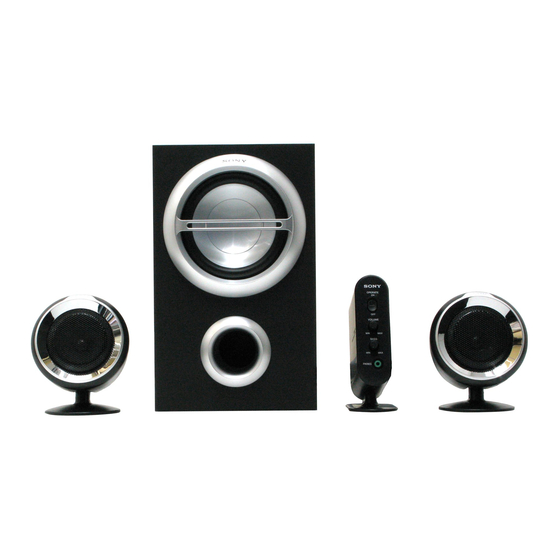
SRS-D211
Satellite
Control Box
Speaker
SPECIFICATIONS
General
Dimensions (w/h/d)
Mass
Cord length
Power consumptions
Power requirements
Where purchased
U.S.A./Canada
Other countries
Design and specifications are subject to change without notice.
ACTIVE SPEAKER SYSTEM
US Model
Canadian Model
E Model
Approx. 50 x 140 x 99 mm (2 x 5
5
/
(Controller)
7
Approx. 98 x 124 x 84 mm (3
/
x 5 x 3
8
(Satellite speaker, on a desk)
Approx. 98 x 98 x 83 mm (3
7
/
x 3
8
(Satellite speaker, attached to a wall)
Approx. 163 x 267 x 301 mm
(6
1
/
x 10
5
/
x 11
7
/
in.) (Subwoofer)
2
8
8
Approx. 134 g (5 oz.) (Controller)
Approx. 294 g (10 oz.) (Satellite speaker)
Approx. 4.2 kg (9 lb. 4 oz.) (Subwoofer)
2 m (Controller to Subwoofer)
2 m (Power cord)
18 W
Operating voltage
120 V AC, 60Hz
• 120 V AC, 60Hz
• 220 - 230 V AC, 50Hz
x 4 in.)
8
3
/
in.)
8
7
/
x 3
3
/
in.)
8
8
Advertisement
Table of Contents

Related Manuals for Sony SRS-D211


Summary of Contents for Sony SRS-D211
-
Page 1: Specifications
• 220 - 230 V AC, 50Hz Output Stereo mini jack x 1 (PHONES) Design and specifications are subject to change without notice. ACTIVE SPEAKER SYSTEM Sony Corporation 9-879-506-02 Personal Audio Group 2005D02-1 Published by Sony Engineering Corporation © 2005.04... -
Page 2: Table Of Contents
SONT CRITIQUES POUR LA SÉCURITÉ DE FONCTIONNEMENT. NUMBERS APPEAR AS SHOWN IN THIS MANUAL OR IN NE REMPLACER CES COMPOSANTS QUE PAR DES PIÈCES SUPPLEMENTS PUBLISHED BY SONY. SONY DONT LES NUMÉROS SONT DONNÉS DANS CE MANUEL OU DANS LES SUPPLÉMENTS PUBLIÉS PAR SONY. -
Page 3: General
SRS-D211 SECTION 1 SECTION 2 GENERAL DIAGRAMS This section is extracted from instruction manual. LOCATING THE CONTROLS THIS NOTE IS COMMON FOR PRINTED WIRING BOARDS AND SCHEMATIC DIAGRAMS. (In addition to this necessary note is printed in each block.) For schematic diagrams. -
Page 4: Schematic Diagram - Amp Section
SRS-D211 Ver. 1.1 2-1. SCHEMATIC DIAGRAM – AMP SECTION – SRS-D211... -
Page 5: Printed Wiring Boards- Amp Section
SRS-D211 Ver. 1.1 2-2. PRINTED WIRING BOARD – AMP SECTION – SATELLITE SATELLITE CONTROL SPEAKER SPEAKER BOARD (R-CH) (L-CH) (Page 7) • Semiconductor FRONT R FRONT L SPEAKER Location (SUB WOOFER) Ref. No. Location BOARD D1001 D1002 AC IN TRANS A... -
Page 6: Schematic Diagram - Control Section
SRS-D211 2-3. SCHEMATIC DIAGRAM – CONTROL SECTION – SRS-D211... -
Page 7: Printed Wiring Boards - Control Section
SRS-D211 2-4. PRINTED WIRING BOARD – CONTROL SECTION – CONTROL BOARD POWER POWER VOLUME INPUT 2 BASS (INPUT PLUG) PHONES 1-865-414- (11) BOARD (Page 5) • Semiconductor Location Ref. No. Location D701 D703 IC801 IC803 Q703 Q705 Q706... -
Page 8: Exploded Views
SRS-D211 Ver. 1.1 SECTION 3 EXPLODED VIEWS NOTE: • -XX, -X mean standardized parts, so they may • The mechanical parts with no reference number have some differences from the original one. in the exploded views are not supplied. The components identified by mark 0 or •... -
Page 9: Control Box, Satellite Speaker Section
SRS-D211 Ver. 1.1 3-2. CONTROL BOX, SATELLITE SPEAKER SECTION Ref. No. Part No. Description Remarks Ref. No. Part No. Description Remarks 2-345-704-01 KNOB, POWER X-2055-350-1 CABINET (S) FRONT SUB ASSY (SILVER) (US) 2-345-702-01 CABINET (C), FRONT 1-826-096-11 SPEAKER UNIT (57mm) -
Page 10: Electrical Parts List
SRS-D211 Ver. 1.1 SECTION 4 ELECTRICAL PARTS LIST NOTE: • Due to standardization, replacements in the • RESISTORS parts list may be different from the parts All resistors are in ohms. The components identified by mark 0 specified in the diagrams or the components... - Page 11 SRS-D211 CONTROL Ref. No. Part No. Description Remarks Ref. No. Part No. Description Remarks FH906 1-533-313-11 FUSE HOLDER A-1103-095-A CONTROL BOARD, COMPLETE ********************* FH907 1-533-313-11 FUSE HOLDER FH908 1-533-313-11 FUSE HOLDER 1-830-411-11 CABLE 6P 2-345-705-01 KNOB, VOLUME < IC >...
-
Page 12: Phones
SRS-D211 Ver. 1.1 CONTROL TRANS A TRANS B Ref. No. Part No. Description Remarks Ref. No. Part No. Description Remarks FB701 1-216-864-11 SHORT CHIP < SWITCH > FB702 1-216-864-11 SHORT CHIP FB703 1-216-864-11 SHORT CHIP S701 1-571-478-11 SWITCH, SLIDE (POWER) - Page 13 SRS-D211 MEMO...
-
Page 14: Revision History
SRS-D211 REVISION HISTORY Clicking the version allows you to jump to the revised page. Also, clicking the version at the upper right on the revised page allows you to jump to the next revised page. Ver. Date Description of Revision 2005.02...