
Related Manuals for Toshiba Surveillix EAV16-480


Summary of Contents for Toshiba Surveillix EAV16-480
- Page 1 EMBEDDED RECORDER Model: EAV16-480 User’s Manual For information on our latest products and peripheral devices, refer to the following web site: www.toshibasecurity.com If the URL changes, refer to www.toshiba.com...
- Page 4 This software and documentation are copyrighted. All other rights, including ownership of the software, are reserved to TAIS. TAIS and Surveillix, are registered trademarks of TAIS in the United States and elsewhere. All other brand and product names are trademarks or registered trademarks of the respective owners.
-
Page 5: Important Safeguards
IMPORTANT SAFEGUARDS Read Owner’s Manual – After unpacking this product, read the owner’s manual carefully, and follow all the operating and other instructions. Power Sources – This product should be operated only from the type of power source indicated on the label. If not sure of the type of power supply to your home or business, consult product dealer or local power company. -
Page 6: Notes On Handling
adjustment of other controls may result in damage and will often require extensive work by a qualified technician to restore the unit to its normal operation If the unit has been dropped or the enclosure has been damaged. When the unit exhibits a distinct change in performance - this indicates a need for service. - Page 7 NOTES ON MAINTENANCE This recorder is designed to last for long periods of time. To keep the recorder always operational we recommend regular inspection maintenance (cleaning parts or replacement). For details contact the nearest dealer. NOTES ON MOISTURE CONDENSATION Moisture condensation could damage the recorder. Read the following information carefully. Moisture condensation might occur under the following circumstances: ...
-
Page 8: Explanation Of Graphical Symbols
EXPLANATION OF GRAPHICAL SYMBOLS The lightning flash with arrowhead symbol, within an equilateral triangle, is intended to alert the user to the presence of un-insulated "dangerous voltage" within the product enclosure that may be of sufficient magnitude to constitute a risk of electric shock to persons. FCC STATEMENT This equipment has been tested and found to comply with the limits for a Class A digital device, pursuant to Part 15 of the FCC Rules. -
Page 9: Limited Warranty
Surveillix DVR Support Center factory. During this period, ISD will repair or replace a defective product or part with a new or refurbished item. The user must deliver the entire product to the Surveillix DVR Repair Facility. -
Page 10: Table Of Contents
TABLE OF CONTENTS Introduction ............................14 Product Description ......................14 Features .......................... 15 USB Flash Drive Approved List ..................15 PTZ Compatibility List ..................... 16 Quick Start Instructions ....................17 Logging In for the First Time ................... 17 ... - Page 11 PTZ Setup ....................... 34 Spot / Sequence Setup .................... 35 Monitor Setup ......................36 Record ..........................37 Recording Setup ...................... 37 Frame ....................... 37 Schedule ......................38 Holiday Setup ....................40 Audio ........................
- Page 12 Express Search ....................... 61 Event Search ......................61 Jump to First Saved Data ..................61 Jump to Last Saved Data ..................61 Daylight Saving Search ................... 62 Search Popup Menu ....................62 Backup (Export) ......................63 ...
- Page 13 Notes...
-
Page 14: Introduction
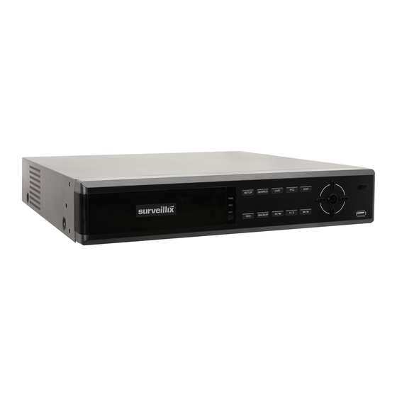
INTRODUCTION PRODUCT DESCRIPTION Toshiba’s EAV recorders are powerful and affordable video management solutions, designed for easy installation and operation. Preconfigured for continuous recording and DDNS, with no additional setup required, the EAV offers quick search, setup, and backup features. EAV recorders use an embedded Linux operating system, which provides stability and protection from viruses. -
Page 15: Features
FEATURES The EAV includes the following features: 16 composite video input connectors Compatible with color (NTSC or PAL) and B&W video sources Multiple search methods (Calendar, Event) Records up to 240 NTSC Images Per Second (IPS) ... -
Page 16: Ptz Compatibility List
PTZ COMPATIBILITY LIST Toshiba EAV recorders support a wide selection of PTZ camera protocols: Toshiba – Pelco D Pelco-D American Dynamics Pelco-P DynaColor PTC-400C D-Max RS-485 DIRECT ERNITech SCC-641 FastraxII SCC-645A Ganz-PT SDM-100 Honeywell MAXPRO SJ-3728R1 Honeywell VCL SK-P Honeywell (GC-655P) SK-S Honeywell (HSD-250) SPD-1600... -
Page 17: Quick Start Instructions
QUICK START INSTRUCTIONS Turn on the recorder. See the Turning on the Recorder section of this manual for more details. Log in. The default password is 1234 Complete System Setup to set up the date, time and system ID. See the System section for more details. -
Page 18: Installation
INSTALLATION FRONT PANEL CONTROLS 16 Channel LED Indicators Power Rec Network Power Enter USB Port... -
Page 19: Rear Panel Connectors
REAR PANEL CONNECTORS The rear panel of the recorder contains virtually all of the connectors you will be using. The diagram below shows the location and description of each connector. 16 Channel Network port HDMI output Audio input Video In ports Audio output VGA output Primary and Spot... -
Page 20: Connection Guide
CONNECTION GUIDE Connecting the Monitor There are three available monitor outputs on EAV recorders. HDMI output for HDMI monitor Composite Monitor output for CCTV monitor – BNC (TV OUT) Spot monitor output for CCTV monitor – BNC (Marked SPOT) ... -
Page 21: Connecting A Ptz Camera
Connecting a PTZ Camera The RS485 connector can be used to control Pan / Tilt / Zoom (PTZ) cameras. See the PTZ camera manufacturer’s manual for configuring the RS485 connection. Connect RX-/TX- and RX+/TX+ of the control system to the TX-/RX- and TX+/RX+ (respectively) of the recorder. -
Page 22: Turning On The Recorder
TURNING ON THE RECORDER Connect camera cables. Connect a network cable and a monitor cable. Connect the power cable to the recorder and wait until the main screen is displayed on the connected monitor; this process will take approximately two minutes. See the Connection Guide section for more details. - Page 23 Notes:...
-
Page 24: Setup
SETUP SETUP MENUS Use the setup menus to configure all of the recorder settings, schedule recording, networking and shutdown. Connect a USB mouse to the recorder to navigate setup menus and recorder functions. See the Logging In for the First Time section if entering setup for the first time If you do not have a USB mouse, you can press the SETUP key on the front of the recorder to enter the setup menus and log in. -
Page 25: Quick Setup
QUICK SETUP The Quick Setup allows you to define global recording settings for an easy and custom recording schedule on the recorder. Global Resolution – 352x240 / 704240 / 704480. Record Mode – CONTINUOUS / MOTION / SENSOR / CONTINUOUS+MOTION / CONTINUOUS+SENSOR / MOTION+SENSOR Average Days to Record –... -
Page 26: System
SYSTEM System Setup To enter System Setup, click MENU on the hover menu, and then click SETUP. Click SYSTEM, and then click SYSTEM SETUP. Click SAVE to save your updates. Video Format - NTSC / PAL, Display only. Use the PAL/NTSC switch on the back of the recorder to change the setting. Language - ENGLISH / SPANISH / FRENCH [User Selectable]. -
Page 27: Upgrade Firmware
System Setup Continued Use DST – After completing the Time Zone setup, click the USE DST value (ON or OFF) to enable or disable Daylight Saving Time. NTP Type – Click NTP TYPE to enable or disable a Network Time Protocol. In the NTP Type window, enable NTP SERVER, and then type your desired NTP Server URL. -
Page 28: Disk Setup
Disk Setup Format Shows installed Hard Disk Drives and the status of other attached storage devices. To format a Hard Drive or USB device, select the appropriate device, click FORMAT, and then click YES. Refer to the list of Approved USB Flash Drives in the Introduction of this manual. To refresh the list of connected USB devices, click RESET. -
Page 29: Overwrite
Overwrite Set options for overwriting data when the Hard Disk Drive becomes full. Enable HDD OVERWRITE to allow the recorder to write over previously recorded data, starting with the oldest date, when the HDD is full. If set to DISABLE the recorder will not record any new data once the HDD becomes full. -
Page 30: Smart Check
SMART Check S.M.A.R.T. = Self Monitoring Analysis & Reporting Technology. Enable SMART Check to detect signs of HDD failure. Set ENABLE S.M.A.R.T. to ENABLE or DISABLE. Set a CHECK INTERVAL between 1 and 24 hours. Define a TEMP THRESHOLD and select Celsius or Fahrenheit. Note The recommended upper optimum operating temperature for the HDD is between 104°... -
Page 31: User Setup
User Setup Use the User Setup to Add or Delete users. -
Page 32: Adding / Changing A User
Adding / Changing a User To add a new user: Click MENU on the hover menu and click SETUP. Click SYSTEM, and then click USER SETUP. Click ADD/CHANGE. Type a USER name. Type a PASSWORD and CONFIRM for the new user. Select the FUNCTION and SETUP access options for the user. -
Page 33: Configuration
Configuration Import and Export current settings. See details in the Save Settings section. Shutdown Use Shutdown to safely shutdown the system. On the hover menu, click MENU, and then click SETUP. Click SYSTEM, and then click SHUTDOWN. Click OK. Turn the power off when shutdown is complete by unplugging the power adapter cord on the back of the recorder. -
Page 34: Color Setup (Adjust)
Color Setup (Adjust) CAMERA – 1 ~ 16 [camera to apply color settings to] BRIGHTNESS – 0 ~ 20 CONTRAST – 0 ~ 20 COLOR – 0 ~ 20 DEFAULT – Apply default system color settings APPLY ALL – Apply current color settings to all cameras PTZ Setup CH –... -
Page 35: Spot / Sequence Setup
Spot / Sequence Setup Spot/Sequence Setup allows you to set the parameters for the SPOT OUT on the recorder and the local live view sequencing. SPOT – Configure the SPOT OUT connection. INTERVAL – Set the sequence interval time (1 ~ 100 seconds). POPUP –... -
Page 36: Monitor Setup
Monitor Setup TRANSPARENCY SETUP – Set the transparency of the setup windows (0 ~ 20). VGA RESOLUTION – Set monitor resolution. FIT-IN VGA – Adjusts the display to display properly on a VGA monitor. When FIT-IN VGA is not selected, the display is adjusted to display on a monitor connected to the TV Out BNC output. -
Page 37: Record
RECORD Recording Setup Frame ON/OFF – Enable or disable recording on individual camera channels. SIZE – Choose the recording resolutions (352240 / 704240 / 704480 / 960x480). IPS – Choose the recording rate (1~30 Images Per Second). QUALITY – Choose the image quality (LOW / NORMAL / HIGH / HIGHEST). INTENSIVE –... -
Page 38: Schedule
Schedule Set the recording schedule for each camera: On the hover menu, click MENU, and then click SETUP. Click RECORD, and then click SCHEDULE. Select a camera to create a recording schedule, or select ALL. Select your desired RECORD MODE. Click hour block or the day of the week to set the entire day. - Page 39 SENSOR Sensor-activated recording. Orange In sensor mode, the unit will record when a sensor is triggered - during DURATION time as set in RECORD > MOTION /EVENT CONFGURATION > ACTION. CONT+MOT Continuous and motion detection recording Sky Blue The unit records in CONTINUOUS mode but switches to MOTION when motion is detected in the motion area.
-
Page 40: Holiday Setup
Holiday Setup Add a recording schedule for a specific date in HOLIDAY SETUP. You can add up to 32 individual holiday recording schedules. To add a new HOLIDAY schdule: On the hover menu, click MENU, and then click SETUP. Click RECORD, and then click RECORD SETUP. Click SCHEDULE. -
Page 41: Emergency Recording
Emergency Recording Configure the recording settings for Emergency Recording and Instant Backup to use when they are activated. Emergency Record: IPS – Set the recording rate per camera (in Images Per Second). QUALITY – Set the picture quality (affects file size). SIZE –... -
Page 42: Motion/Event Setup
Motion/Event Setup Motion / Event Setup has four sections; Input, Sensor, Action, and Alarm Monitor. When an event occurs (Input), the unit records the image according to its settings (Camera Setup) and triggers an alarm (Action). Input CH – Channels 1-8 will appear by default. To view channels 9-16, click CH. MOTION –... -
Page 43: Setting Up Motion Detection Recording
Setting Up Motion Detection Recording To record data only when motion is detected: On the hover menu, click MENU, and then click SETUP. Click RECORD, and then click MOTION/EVENT SETUP. Set MOTION to ON. Set the motion SENSITIVITY level. [1~10]. To set a global motion area (each channel can also be configured individually), click AREA. -
Page 44: Sensor
Sensor Sensor Setup Set the Sensor TYPE to N/O (Normally Open) or N/C (Normally Closed). Repeat for all sensors. Click SAVE. Alarm Setup Enable or disable the SIGNAL (ON / OFF). Set each alarm TYPE (NO / NC). Repeat for all relays. Click SAVE. -
Page 45: Action
Action CH – Channels 1-8 will appear by default. To view channels 9-16, click CH. Alarm – Associate an alarm relay with a camera channel (OFF / 1). Delay – Set the delay time for relay to activate (0~100 seconds). Duration –... -
Page 46: Alarm Monitor
Alarm Monitor Send event information to a remote client using the Alarm Monitor software. Set SEND TO ALARM MONITOR to ON. Select the types of events to send to the Emergency Agent (MOTION, SENSOR, MOTION + SENSOR). Type the IP ADDRESS of the remote client. Type the PORT number. -
Page 47: Network
NETWORK Network Setup Configure network settings. Network HOST NAME – Host name for the recorder on the network. NETWORK TYPE – Select STATIC IP to manually define a static IP address. Select DHCP for a DHCP server to assign an IP address automatically. Contact your network administrator for more information. -
Page 48: Serial Setup
DDNS - Dynamic Domain Name Service (DDNS) is a service that allows a connection to an IP address using a hostname (URL) address instead of a numeric IP address. Most Internet Service Providers use Dynamic IP Addressing that frequently changes the public IP address of your internet connection;... -
Page 49: E-Mail Setup
E-mail Setup The recorder can send an e-mail notification to up to six defined e-mail addresses when an event happens. E-MAIL SERVER – Configure the recorder to use selected e-mail server (DVR / SMTP). OPTION – Define the type of event that will trigger an e-mail notification. MOTION –... -
Page 50: Mysurveillix
MySurveillix To enable MySurveillix on your recorder during the initial configuration: Click ENABLE MYSURVEILLIX NOW. Note To enable MySurveillix at any time after the initial configuration, go to NETWORK > MYSURVEILLIX SETUP and then set ENABLE MYSURVEILLIX to ON. Log in using the admin user account. (default username: admin, password: 1234) Set the CUSTOM DAY/NIGHT TIME. -
Page 51: Information
INFORMATION System Log View Displays system log information. System Log View displays the recent activity of all users on the recorder. You can export and save the System Log to review user activity. Version View Displays system information and software version information for the recorder. -
Page 52: Status View
Status View Displays status screens for: Disk Record Audio... - Page 53 Status View continued Sensor Network Event...
- Page 54 Notes:...
-
Page 55: Operation
OPERATION LOGIN The LOG-IN window will display on the monitor until a user logs in with the correct ID and password. To prevent unauthorized changes to the system settings, the administrator should change the default administrator password and create a User account. Default Administrator Log In The default administrator account login is: USER: admin... -
Page 56: Icons
Icons In Live mode, icons or messages on the screen indicate the system mode or status. Right-upper corner on each CH. Right-bottom corner on full screen. Continuous Recording No HDD, Smart Alarm & HDD Failure Motion Detection Using Emergency Recording Recording Sensor Activated Using PTZ... -
Page 57: Mouse-Over Menu
Mouse-Over Menu Move the mouse to the bottom of the monitor in live mode. The hover menu will appear. Sequence – Click to start camera sequence. Emergency Recording – Click to start instant recording. In instant recording mode, the system records all channels at the recording rate configured on the Emergency Recording screen. -
Page 58: Popup Menu
Popup Menu Right-click the live screen to open the Popup Menu. HIDE LIVE VIEW – Hide the selected camera from Live view. RECORD CHANGE – Change the recording settings for that channel including PPS, quality, resolution and event response. PAGE SEQUENCE – The SEQ icon appears on the bottom right of the screen and displayed channels will be sequentially changed. -
Page 59: Ptz
To enter PTZ mode: Right-click the Live screen and select PTZ on the pop-up menu. Click the PTZ icon on the hover menu. Drag the mouse up/down or left/right to move pan/tilt position of the camera. As you move the mouse away from the center of the screen, the camera movement speed increases. -
Page 60: Search
SEARCH Searching Recorded Data Search recorded video on the recorder to find a specific time or event. On the hover menu, click MENU, and then click SEARCH. Select your TARGET media (HDD / USB). Select your desired search method. Quick Search ... -
Page 61: Quick Backup In Search Mode
Quick Backup in Search Mode You can easily archive video while watching a video playback. Note: The Quick Backup is only available using the BACKUP button, provided on the 16 CH EAV recorder. In the search mode: Press the BACKUP on the front panel to set the Start time. You will see S [Date/Time of clip] in right bottom of the playback monitor. -
Page 62: Daylight Saving Search
Daylight Saving Search Daylight Saving Search is used to find recorded data after switching the time at the end of Daylight Saving Period. The System will record data with the same time stamp for two hours when they are repeated. If any overlapped time data exists the system will display the times on this page. -
Page 63: Backup (Export)
BACKUP (EXPORT) Manual Export Back up recorded data on a connected USB device. Using this export method, video data is saved in a proprietary format and must be viewed using the Export Viewer software. To configure a data backup: Click MENU on the hover menu, and then click BACKUP. Connect a USB device. -
Page 64: Using The Backup Player
USING THE BACKUP PLAYER Play recorded video on a PC using Backup Player, the proprietary media player included with every backup file. Controlling Backup Player Next Frame Previous Forward Back Pause... -
Page 65: Setup And Save Functions
Setup and Save Functions These function buttons allow you to configure the Backup Player and save a JPEG image or AVI video. OPEN – Allows you to choose which data to open. When selecting data that is saved to your local hard drive, the video must be in a directory named DATA. Navigate to the folder above the DATA directory and click OK to see the available playback options. -
Page 66: Screen Division Buttons
Screen Division Buttons The Screen Division buttons allows you to view cameras in groups such as two by two, three by three and four by four. The button options are shown below. Single Channel View – Displays one camera channel. To return to a different Multi-Camera View, select a different Screen Division button. -
Page 67: Save Settings
SAVE SETTINGS Use the System Setup menu to export and import saved or factory default system settings. Save Settings On the hover menu, click MENU, and then click SETUP. Click SYSTEM, and then click CONFIGURATION. Select an empty PROFILE and define a name for the settings configuration. To save settings to a USB device, click EXPORT. -
Page 68: Remote Software
REMOTE SOFTWARE SCS OVERVIEW SCS is Video Management Software from Toshiba that allows you to access your recorder from any PC or laptop with a network connection. Use SCS to monitor live video, search recorded video, control PTZ cameras, export video, and even search live video as it happens. -
Page 69: Web Viewer Overview
WEB VIEWER OVERVIEW The recorder allows access to the video using Microsoft® Internet Explorer® browser versions 6 and above. To log in to the recorder server from the Web Viewer, a user account must be made for the user. This ensures that only authorized users are allowed to log in. In addition, each user can be assigned different privileges that allow or deny access to different functions. -
Page 70: Connecting To A Recorder Using Web Viewer
Connecting to a Recorder Using Web Viewer Open Microsoft Internet Explorer. Enter the IP address of the recorder into the Address bar. When attempting this for the first time you will be asked to accept an Active X installation. Click Yes. Note If you receive a message saying Internet Explorer security settings do not allow you to download Active X components then you will need to adjust the browser security... -
Page 71: Performing A Basic Search
Performing a Basic Search Click the Calendar icon to open the calendar and select a date. Select a time using the hour and minute control bars. Select one or more cameras. Click Play. (Video can be played forwards, backwards, or frame-by-frame.) Status Search The Status Search option displays a timeline in graph format. -
Page 72: Print
Print Use the Search screen to locate the desired frame. Double-click the image. Note Only one camera can be selected at a time for this function to work. Click Print. The Print Options window opens. Depending on the printer being used, there may be several printing options available. -
Page 73: Digital Verifier Overview
DIGITAL VERIFIER OVERVIEW JPG images and AVI video files that are exported from the recorder are automatically embedded with a digital signature. Digital signatures are a way to verify the authenticity of the images to ensure that they have not been tampered with or edited in any way. Included on the Software Installation DVD, supplied with the recorder, is the Digital Signature Verification program. -
Page 74: Appendix
APPENDIX BUTTON INDEX LED Status Indicators 16 Channel Power Illuminates when power is supplied to the recorder. Record Flashes when the hard drive is being accessed. Network Illuminates when the recorder is connected to a network. -
Page 75: Function Buttons
Function Buttons 16 Channel Setup Open the setup menu. Search Open the search menu. Live Change the display mode. Display switches in the following order when the LIVE key is pressed successively: (Single > 4 > 7 > 9 > 10 >... -
Page 76: Channel Buttons (Continued)
16 Channel Buttons (continued) Enter Input data, make selections, and open pop-up menus. Navigation Move up. Move the camera view point up. Navigation Move to the right. Move the camera view point to the right. Search Play recorded videos. When pressed successively, the search jumps forward in time by 30 minute increments. -
Page 77: Recorder Specifications
RECORDER SPECIFICATIONS Model EAV16-480 Camera Channels Looping Outputs Max IPS Per Channel Recording Rate (IPS) Live Display Rate (IPS) 240+ Audio Channels Video Outputs 1 VGA, 1 HDMI, 1 Spot Out/TV Out (BNC) Digital Relay Outputs Alarm Sensor Inputs Image Compression H.264... - Page 78 www.toshibasecurity.com 1-877-855-1349 © 2014 Toshiba All rights reserved. No part of this publication may be reproduced by any means without written permission from Toshiba. The information in this publication is believed to be accurate in all respects. However, Toshiba cannot assume responsibility for any consequences resulting from the use thereof.