JVC TK-C2201WPE(EX) Instruction Manual
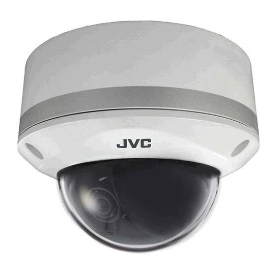
Outdoor dome camera
Hide thumbs
Also See for TK-C2201WPE(EX):
- Specifications (2 pages) ,
- Instructions (2 pages) ,
- Menu setting (17 pages)
Table of Contents
Advertisement
Quick Links
Download this manual
See also:
Instructions
Advertisement
Table of Contents

Related Manuals for JVC TK-C2201WPE(EX)


Summary of Contents for JVC TK-C2201WPE(EX)
- Page 1 OUTDOOR DOME CAMERA INSTRUCTIONS TK-C2201WPU (For USA and Canada) TK-C2201WPE(EX) (For Europe) For Customer Use: Enter below the Serial No. which is located on the body. Retain this information for future reference. Model No. TK-C2201WPU Serial No. LST0979-001C...
-
Page 2: Table Of Contents
Introduction Contents Introduction Contents ......................2 Features ......................3 Operating Precautions ..................4 Name of Parts ....................6 Setup About Connection Cables ................10 Setting the Switches ..................12 Installation Mounting the Camera ..................13 Adjustment Adjusting Image ....................23 Adjusting the Auto White Balance .............. -
Page 3: Introduction
: Indicates a reference page or item. Contents of this manual JVC KENWOOD Corporation holds the copyright to this manual. Any part or all of this manual may not be reproduced without prior consent from the company. -
Page 4: Operating Precautions
Introduction Operating Precautions Storage and Location of Use Do not install the camera in the following places. - In a place with vapor or oil, for example in a kitchen. - When the ambient temperature rises above or falls below the acceptable range (from -10 f to 50 f) - In a place at which corrosive gases are emitted. - Page 5 Introduction Disclaimer We will not be responsible for any inconveniences or disturbances caused in the event of privacy invasion as a result of camera footages of this product. Others When using this camera with [AGC] set to "MID" or "HIGH", the sensitivity increases automatically for dark images and the screen may appear grainy, but this is not a malfunction.
-
Page 6: Name Of Parts
Introduction Name of Parts Camera Mounting Hole (A page 14) Fall Prevention Wire Mounting Screw (A page 14) Conduit Plug/Hole (side) (A page 21) Dome Cover (A page 13) Inner Dome (A page 13) Video signal output connector (BNC) (A page 10) (A page 15) - Page 7 Introduction Protection Cover (A page 15) Power Supply Cable (A page 11) (A page 15) Hole for Connecting Cables, Conduit Hole (A page 20) Base (A page 19) Dome Cover Fastening Screw (A page 13)
- Page 8 Introduction Name of Parts (Continued) Camera (Interior) The dome cover and inner dome are removed. F ADJ MENU MONITOR Focus Adjustment Ring (A page 25) Zoom Adjustment Ring (A page 25) Rotation Knob (A page 24) Fall Prevention Wire (To prevent the dome cover from dropping) (A page 13) Camera Unit Fastening Screw (A page 19)
- Page 9 Introduction Space for Inserting Heater When mounting the heater (sold separately: KA-ZH215U), read the instruction manual of the heater before mounting. Power Supply Connector for Heater For connecting to the power supply connector of the heater. Tilt Fastening Screw (A page 24) [MONITOR] Terminal (RCA pin) (A page 23) Lug Plate...
-
Page 10: Setup
Setup About Connection Cables The maximum connection distance varies with the type of cable used. Be sure to turn off the power of devices before connecting cables. To video Signal Cable To Power Supply Connect to AC 24 V power supply if using the heater (sold separately: Memo KA-ZH215U). - Page 11 Do not connect the AC 24 V cable to commercial power supply. If it is connected by mistake, the internal circuit may be damaged. Do not use the camera and make sure to send it to the nearest JVC dealer for inspection.
-
Page 12: Setting The Switches
Setup Setting the Switches Before mounting the camera, set the function setting switches on the camera. To set the switches, use a fine-tipped screwdriver. DIP Switch Settings Chart AUTO MONITOR TYPE NOT UESD Function selection switches 1 [D/N AUTO/OFF] Day & Night Switch Set this to "AUTO"... -
Page 13: Installation
Installation Mounting the Camera Selecting a mounting method Mount directly to the ceiling or on the wall (A page 13) Mounting the Camera Using the Conduit Hole at the Bottom of the Base (A page 19) Mounting the Camera Using the Conduit Hole at the Side of the Base (A page 21) Mounting the Camera using the Electrical Box (A page 22) Memo When mounting the camera to the ceiling, ensure to wear safety glasses... -
Page 14: Mounting The Camera Unit
Installation Mounting the Camera (Continued) Mounting the Camera Unit 1 Make a hole (Φ30 mm) in the ceiling using the template provided 2 Mount the fall prevention wire for connecting the camera unit to the ceiling The fall prevention wire is not provided. Prepare a wire, taking into due consideration the length, strength, pull and material (insulating). - Page 15 Installation Connecting the cable For safety reasons, turn on the power only after all the connection is complete. The status indicator lights up when the camera is turned on. 1 Connect the coaxial cable (A page 10) Lower the protection cover and connect the connectors. Upon connecting, restore the protection cover to cover the connectors.
- Page 16 Installation Mounting the Camera (Continued) Process after connection Fill the conduit hole and mounting holes with sealing agent and insert the silica gel. 1 Fill the conduit hole and the screw mounted holes (2 locations) with sealing agent (GE silicon) Seal the holes completely.
-
Page 17: Adjusting Images
Installation Adjusting images After mounting is completed, adjust the images while checking the actual image. (A page 23) Mounting the Dome Cover Attach the dome cover back when all settings are finished. 1 Mount the inner dome Mount the inner dome in a way that supports the tilt direction of the lens. Insert the inner depression of the inner dome into the protruding parts beside the fastening screw. - Page 18 Installation Mounting the Camera (Continued) 2 Mount the dome cover ① Clean the dust and dirt on the dome cover. ② Align the position marks (3 locations) on the camera unit and dome cover, followed by pressing in directly to mount the cover. ③...
- Page 19 Installation Mounting the Camera Using the Conduit Hole at the Bottom of the Base Conduit hole: G3/4-14 UNC (TK-C2201WPU), M25 (TK-C2201WPE) 1 Remove the dome cover and inner dome (A page 13) 2 Remove the camera unit from the base and mount the fall prevention wire to the camera unit ①...
-
Page 20: Camera Mounting
Installation Mounting the Camera (Continued) 3 Wind the sealing tape Wind the sealing tape around the pipe junction (where the conduit hole thread lines with the pipe screw hole) two or more times. 4 Mount the base to the pipe Turn and screw the base unit to the pipe in the clockwise direction. - Page 21 Installation Mounting the Camera Using the Conduit Hole at the Side of the Base If the camera cannot be mounted directly to the ceiling, use the conduit hole at the side of the base to mount the camera to the pipe. Conduit hole: G3/4-14 UNC (TK-C2201WPU), M25 (TK-C2201WPE) 1 Remove the dome cover and inner dome (A page 13) 2 Remove the camera unit from the base and mount the fall...
- Page 22 Installation Mounting the Camera (Continued) Mounting the Camera using the Electrical Box 1 Remove the dome cover and inner dome (A page 13) 2 Mount the camera unit to the electrical box Mount the camera unit to the electrical box using the mounting hole (2 locations) with the M4 screw (2 pieces).
-
Page 23: Adjustment Adjusting Image
Adjustment Adjusting Image After mounting the camera, adjust the images while looking at the actual image. Discharge the static electricity from your body by touching the metallic part of the monitor terminal before handling the camera as static electricity may cause the camera to malfunction. - Page 24 Adjustment Adjusting Image (Continued) 3 Adjust the shooting direction of the camera Adjust the camera for pan, tilt and rotation, and face the camera towards the subject. Pan: Tilt fastening screw Tilt: Rotation: Shooting direction mark Pan center mark Rotation center mark Rotation knob ( 2) Rotate both pan 175 and rotation...
- Page 25 Adjustment 4 Adjust the image size Loosen the fastening screw for the zoom adjustment ring and move the ring to the left/right to adjust the image size. After adjustment is complete, fasten the screw. 5 Adjust the focus ① Hold the focus adjust gear knob, shift the catch from point A to point B as illustrated in the diagram to disengage the gear.
- Page 26 Adjustment Adjusting Image (Continued) 6 Fine adjust the focus ① Press and hold the [J] button. Focus adjust mode will be activated and "FOCUS ADJUST MODE" is displayed on the monitor screen. The contours are emphasized as the iris opens and the depth of field becomes shallow.
- Page 27 Adjustment 7 Tighten the fastening screw of the focus adjustment ring Hold and press the focus adjust gear between your fingers in the direction of the arrows in the diagram, and tighten the fastening screw of the focus adjustment ring. Focus adjustment ring...
-
Page 28: Adjusting The Auto White Balance
Adjustment Adjusting the Auto White Balance Each light source has its own color temperature. Therefore, when the main light source lighting the subject is changed, adjust the white balance again. 1 Press the [MENU] button. 2 Select [WHITE BALANCE] with the [J/K] button and "AWC" with the [H/I] button, then press the [SET] button. -
Page 29: Others
Others Specifications Video S/N ratio : 52 dB (typical, AGC OFF) Minimum : Color mode: illumination 0.05 lx (typical, 50 %, F1.2, AGC HIGH) Black and White mode: 0.03 lx (TK-C2201WPU) (typical, 50 %, F1.2, AGC HIGH) 0.006 lx (TK-C2201WPE) (typical, 50 %, F1.2, AGC HIGH) Zoom ratio : 3.75 Focal length... - Page 30 Others Specifications (Continued) Accessories : (TK-C2201WPU) WARRANTY CARD INSTRUCTIONS Silica gel Wrench Template (TK-C2201WPE) INSTRUCTIONS Silica gel Wrench Template...
- Page 31 Others External dimensions [Unit: mm (inch)] 121(4-3/4) 113(4-1/2) (3/8) Screw for conduit (bottom surface, side surface) (TK-C2201WPU: G3/4-14 UNC, TK-C2201WPE: M25) * Specifications and appearance of this camera are subject to change for improvements without notice.
- Page 32 2012 JVC KENWOOD Corporation LST0979-001C...