Table of Contents
Advertisement
Advertisement
Table of Contents

Related Manuals for Motorola RS507-IM2xxxxSTWR


Summary of Contents for Motorola RS507-IM2xxxxSTWR
- Page 1 RS507 Hands-Free Imager Product Reference Guide...
-
Page 2: Rs507 Hands-Free Imager Product Reference Guide
RS507 Hands-Free Imager Product Reference Guide 72E-120802-01 Rev. B September 2011... -
Page 3: Warranty
Motorola. No right to copy a licensed program in whole or in part is granted, except as permitted under copyright law. The user shall not modify, merge, or incorporate any form or portion of a licensed program with other program material, create a derivative work from a licensed program, or use a licensed program in a network without written permission from Motorola. -
Page 4: Table Of Contents
Table of Contents Warranty ........................ii Revision History......................ii About This Guide Introduction ........................xiii Documentation Set ......................xiii Model Configurations..................... xiii Chapter Descriptions ..................... xiv Notational Conventions....................xiv Related Documents ....................... xv Service Information......................xv Chapter 1: Getting Started Introduction ........................ - Page 5 RS507 Hands-Free Imager Product Reference Guide Establish Bluetooth Connection ................1-11 Restore Lost Bluetooth Connection ................ 1-12 Remove Bluetooth Connection ................1-12 Pairing Bar Code Format ..................1-13 Scan ..........................1-14 Scan Triggering Modes ................... 1-14 Aiming the Imager ....................1-15 Customize the Imager ....................
- Page 6 Table of Contents Chapter 4: RS507 Update and Configuration Introduction ........................4-1 Configuring the Imager ....................4-1 Introduction ......................4-1 Control Panel Application ..................4-2 RSMSample Application ..................4-3 Imager Attributes ..................... 4-7 Imager Motion and Proximity Configuration ............4-11 ..........................
- Page 7 viii RS507 Hands-Free Imager Product Reference Guide Enable/Disable UPC-A .................... 6-7 Enable/Disable UPC-E .................... 6-7 Enable/Disable UPC-E1 ..................6-8 Enable/Disable EAN-8/JAN-8 ................. 6-8 Enable/Disable EAN-13/JAN-13 ................6-9 Enable/Disable Bookland EAN ................6-9 Decode UPC/EAN/JAN Supplementals ..............6-10 User-Programmable Supplementals ............... 6-13 UPC/EAN/JAN Supplemental Redundancy ............
- Page 8 Table of Contents Set Lengths for Interleaved 2 of 5 ................6-41 I 2 of 5 Check Digit Verification ................6-43 Transmit I 2 of 5 Check Digit ................... 6-43 Convert I 2 of 5 to EAN-13 ..................6-44 Discrete 2 of 5 (DTF) ....................6-44 Enable/Disable Discrete 2 of 5 ................
- Page 9 RS507 Hands-Free Imager Product Reference Guide 2D Symbologies ......................6-68 Enable/Disable PDF417 ..................6-68 Enable/Disable MicroPDF417 ................. 6-68 Code 128 Emulation ....................6-69 Data Matrix ......................6-70 Data Matrix Inverse ....................6-70 Maxicode ......................... 6-71 QR Code ......................... 6-71 QR Inverse ......................6-72 MicroQR ........................
- Page 10 Table of Contents How to demonstrate SPP connection with a computer ........... 7-34 Connecting multiple RS507 into single device ............7-35 How to return to SSI (SCAN) mode ................ 7-35 Switching between SSI (SCAN), HID and SPP ............7-36 Firmware upgrade ......................7-38 Upgrading using a computer and the PC Tool application ........
- Page 11 RS507 Hands-Free Imager Product Reference Guide Glossary Index...
-
Page 12: About This Guide
Advanced Data Formatting Programmer Guide - describes how to customiz data before transmission to the host device. Model Configurations This guide covers the following model configurations: • RS507-IM2xxxxSTWR -Triggered RS507 with standard battery • RS507-IM2xxxxSNWR - Triggerless RS507 with standard battery • RS507-IM2xxxxENWR -Triggerless RS507 with extended battery •... -
Page 13: Chapter Descriptions
• Chapter 7, RS507 Bluetooth Connection Using HID and SPP Profiles describes the Bluetooth connection modes of the RS507 to a personal computer and non-Motorola terminals. • Chapter 8, Specifications provides Imager and charger technical specifications. •... -
Page 14: Related Documents
For the latest version of this guide and all guides, go www.motorola.com/enterprisemobility/manuals. Service Information If you have a problem with your equipment, contact Motorola Enterprise Mobility Support for your region. Contact information is available at: http://www.motorola.com/enterprisemobility/contactsupport. When contacting Enterprise Mobility Support, please have the following information available: •... - Page 15 Suggested steps to reproduce the problem Motorola responds to calls by E-mail, telephone or fax within the time limits set forth in support agreements. If your problem cannot be solved by Motorola Enterprise Mobility Support, you may need to return your equipment for servicing and will be given specific directions.
-
Page 16: Chapter 1 Getting Started
RS507-IM2xxxxCTWR Corded and Triggered RS507 Inspect the equipment for damage. If you are missing any equipment or if you find any damaged equipment, contact the Motorola Enterprise Mobility Support immediately. See Service Information on page xv for contact information. -
Page 17: Introduction
1 - 2 RS507 Hands-Free Imager Product Reference Guide Introduction The RS507 Hands-Free Imager (also referred to as the Imager) is a wearable bar code scan solution for both 1D and 2D bar code symbologies. The Imager is also compatible with a wide range of mobile computers communicating over Bluetooth. -
Page 18: Cordless Configuration Features
Getting Started 1 - 3 Cordless Configuration Features Triggered Configuration Battery Imager Window Battery Release Latch Comfort Pad Trigger Swivel Assembly Finger Strap Scan Trigger Restore Key Asset Control Label Left Scan LED Strap Buckle Beeper Right Scan LED Finger Strap Triggerless Configuration Triggerless Strap Holder RS507 Cordless Configuration Features... -
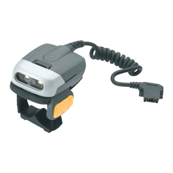
Page 19: Corded Configuration Features
1 - 4 RS507 Hands-Free Imager Product Reference Guide Corded Configuration Features Interface Cable Connector to WT4090 Release Latch Imager Window Corded Adapter Comfort Pad Trigger Swivel Assembly Finger Strap Scan Trigger Restore Key Asset Control Label Strap Buckle Left Scan LED Finger Strap Beeper Right Scan LED... -
Page 20: Trigger Swivel Assembly - Change Trigger Position
Getting Started 1 - 5 Trigger Swivel Assembly - Change Trigger Position The Imager is worn on the index and middle fingers, and triggered with the thumb. The Trigger Swivel Assembly of the Imager rotates to provide left-hand or right-hand use. To change the position of the Trigger: From the bottom of Imager, hold and pull the Comfort Pad off the Imager. -
Page 21: Getting Started - Cordless Configuration
Before using the Imager, charge the battery. The SAC5070 8-Bay Battery Charger supports both standard and extended capacity batteries. To charge the Imager battery, refer to the SAC5070 8-Bay Battery Charger Quick Reference Guide, p/n 72-115989-01 available at: www.motorola.com/enterprisemobility/manuals and search for 'SAC5070'. Install the Battery Align the battery on top of the Imager. -
Page 22: Getting Started - Corded Configuration
Getting Started 1 - 7 Finger Strap Wearing the Imager - Cordless Adapter Figure 1-6 Getting Started - Corded Configuration In order to start using the Imager you must install the Corded Adapter. Connect the Corded Adapter To connect the Corded Adapter: Align the Corded Adapter on top of the Imager. -
Page 23: Connect To A Wt4090 Wearable Terminal
1 - 8 RS507 Hands-Free Imager Product Reference Guide Connect to a WT4090 Wearable Terminal The Imager connects to the Wearable Terminal and mounts on the fingers. WT4090 Interface Connector Interface Cable Connector Disconnect Button Connecting and Disconnecting to a Wearable Terminal Figure 1-8 To connect the Imager to the terminal: On the terminal, remove the cover from the WT4090 Interface Connector. - Page 24 Getting Started 1 - 9 Tighten the Finger Strap. 4t× Finger Strap Wear the Corded Adapter Imager - Finger Strap Figure 1-10 NOTE When using the Imager for the first time, press and release the Scan Trigger to enable the manual triggering mode (this operation disables the default auto triggering mode).
-
Page 25: Status Indications
1 - 10 RS507 Hands-Free Imager Product Reference Guide Status Indications The Imager has two Scan LEDs that provide identical indications. The Imager is also equipped with a beeper that issues different beep sequences and patterns to indicate status. Table 1-2 defines the LED and beep sequences indications that occur during normal operation and bar code scanning. -
Page 26: Bluetooth Connection
Getting Started 1 - 11 Bluetooth Connection Establish Bluetooth Connection To establish Bluetooth connection with a mobile computer: Ensure that the Imager is within a range of 10 meters (30 feet) from the mobile computer. Install the battery in the Imager. Launch the Bluetooth Device (BD) address application (see Figure 1-11) from the mobile computer. -
Page 27: Restore Lost Bluetooth Connection
1 - 12 RS507 Hands-Free Imager Product Reference Guide Figure 1-12 Pairing Bar Code Example as Shown on the Mobile Computer Screen The Scan LED starts flashing green indicating that the Imager is attempting to establish connection with a mobile computer. NOTE If the Imager default PIN code is required for establishing connection, enter the following code: "12345". -
Page 28: To Remove Bluetooth Connection
Getting Started 1 - 13 To remove Bluetooth connection: Scan an un-pairing bar code for disconnecting the Imager from the mobile computer. Un-pairing Bar Code Figure 1-13 The Imager emits one string of high/low beeps indicating that Bluetooth communication with the mobile computer is disconnected. -
Page 29: Scan
1 - 14 RS507 Hands-Free Imager Product Reference Guide Scan The Imager uses digital camera technology to take an image of a bar code and software decoding algorithms are executed to extract the bar code data from the image. Scan Triggering Modes Manual Triggering (Triggered models only) Launch a scanning software application on the mobile computer. -
Page 30: Aiming The Imager
Getting Started 1 - 15 Aiming the Imager The aiming pattern of the Imager is a cross hair laser beam with bright center dot (see Figure 1-15). The virtual rectangle made by the cross hair reflects the field of view of the Imager. The aiming pattern is used to position the bar code within the field of view. -
Page 31: Customize The Imager
1 - 16 RS507 Hands-Free Imager Product Reference Guide When using the application on your mobile computer in “Pick List” mode, the Bright Center Dot can be positioned anywhere on the symbol (see Figure 1-15).The top examples in Figure 1-17 show acceptable aiming options, while the bottom examples can not be decoded. -
Page 32: Changing Triggerless To Triggered Configuration
Getting Started 1 - 17 Changing Triggerless to Triggered Configuration To change from Triggerless to Triggered configuration: Remove the Comfort Pad (see Comfort Pad Replacement on page 3-3). Remove the Triggerless Strap Holder (see Triggerless Strap Holder Replacement on page 3-6). -
Page 33: Chapter 2 Sac5070 8-Bay Battery Charger
USA model SAC5070-801CR International model * For AC line cord, contact the Motorola representative in your country. Inspect the equipment for damage. If you are missing any equipment or if you find any damaged equipment, contact Motorola Enterprise Mobility Support immediately. -
Page 34: Parts Of The Charger
2 - 2 RS507 Hands-Free Imager Product Reference Guide Parts of the Charger Charger Front RS507 Imager Rest Compartment Batteries Age Test Button Charge Status LED Charging Bay Asset Control Label M4 Screw Inserts (X4) Charger Back Wall Mount Hole (X4) (Screws not Included) Power Supply Cable Duct Power Supply Cable Duct... -
Page 35: Installation
SAC5070 8-Bay Battery Charger 2 - 3 Installation Tabletop / Shelf Set Up To set the Charger on a tabletop or shelf: Place the Charger and the Power Supply Unit on a tabletop or shelf. NOTE When required, use the screw inserts at the back and base to secure the Charger to the tabletop or shelf surface. -
Page 36: Wall Mount
2 - 4 RS507 Hands-Free Imager Product Reference Guide Wall Mount For safe mounting, it is essential to use wall anchors appropriate to the wall type (i.e. plaster, WARNING drywall, concrete, etc.). Mount to wood studs whenever possible. To mount the Charger on a wall: Mark the screw location on the wall. -
Page 37: Inserting The Imager Battery In The Charger
SAC5070 8-Bay Battery Charger 2 - 5 Inserting the Imager Battery in the Charger The Charger supports both standard and extended capacity batteries. Charger Bay Standard Battery Inserting the Imager Battery into the Charger Figure 2-4 Charge the Battery Only Lithium-ion batteries that have been designed for use with the RS507 Hands-free Imager can be CAUTION recharged by the Charger. -
Page 38: Battery Age Test
2 - 6 RS507 Hands-Free Imager Product Reference Guide Battery Age Test The battery age test checks the battery capacity when fully charged. A worn-out battery is considered to have less than 80% of its nominal capacity. The battery test is simultaneously performed for all batteries inserted into the charger. -
Page 39: Chapter 3 Troubleshooting & Maintenance
Chapter 3 Troubleshooting & Maintenance Introduction This chapter provides suggested Imager and Charger troubleshooting and maintenance. Troubleshooting Imager Imager Troubleshooting Table 3-1 Problem Cause Solution Laser aiming pattern does Corded: Interface cable is not secure. Verify that the interface cable is properly not display when pressing connected. -
Page 40: Charger
Replace battery with a new one. Contact a service representative (see Service Information on page xv). NOTE If after performing these checks the Charger still experiences problems, contact the distributor or call Motorola Enterprise Mobility Support. See page xv for contact information. -
Page 41: Maintenance
Troubleshooting & Maintenance 3 - 3 Maintenance Cleaning the scan window is the basic maintenance required. A dirty window can affect scanning accuracy. • Do not allow abrasive material to touch the window. • Remove any dirt particles with a damp cloth. •... -
Page 42: Trigger Swivel Assembly Replacement
3 - 4 RS507 Hands-Free Imager Product Reference Guide Installation To install the Comfort Pad: Position the Comfort Pad onto the Imager as shown. Installation of Comfort Pad Figure 3-2 Press the Comfort Pad onto the Imager. When properly installed, the Comfort Pad locks into place. Trigger Swivel Assembly Replacement Removal To remove the Trigger Swivel Assembly:... - Page 43 Troubleshooting & Maintenance 3 - 5 Installation To install the Trigger Swivel Assembly: Turn the Imager upside-down. Position the Trigger Swivel Assembly to align with the back of the Imager. Lower the Trigger Swivel Assembly onto the scan assembly. Trigger Swivel Assembly Installation of Trigger Swivel Assembly Figure 3-4 Rotate the Trigger Swivel Assembly 1/4 turn counterclockwise.
-
Page 44: Triggerless Strap Holder Replacement
3 - 6 RS507 Hands-Free Imager Product Reference Guide Triggerless Strap Holder Replacement NOTE The Triggerless Strap Holder should be installed when the Imager is intended to be used in Motion and Proximity Initiated bar code read mode. Removal To remove the Triggerless Strap Holder: Turn the Imager upside-down. -
Page 45: Finger Strap Replacement (Trigger Swivel Assembly)
Troubleshooting & Maintenance 3 - 7 Lower the Triggerless Strap Holder onto the Imager. Rotate Triggerless Strap Holder 1/4 turn counterclockwise. Finger Strap Replacement (Trigger Swivel Assembly) Removal Remove the Finger Strap from the Strap Buckle. Pull the Finger Strap out of the Trigger Swivel Assembly. Installation Align a new Finger Strap with the Slots in the Trigger Swivel Assembly. -
Page 46: Finger Strap Replacement (Triggerless Strap Holder)
3 - 8 RS507 Hands-Free Imager Product Reference Guide Finger Strap Replacement (Triggerless Strap Holder) Strap Buckles Replacement of Finger Strap (Triggerless Strap Holder) Figure 3-8 Removal Remove the Finger Strap from the Strap Buckles. Installation Slip the Finger Strap through the Strap Buckles. Strap Buckle Replacement Strap Buckle Replacement Figure 3-9... -
Page 47: Field Replaceable Parts
Troubleshooting & Maintenance 3 - 9 Gently press the pin slot of Strap Buckle to engage with the pin of the Trigger Swivel Assembly. The pin slot snaps onto the pin. Install the Trigger Swivel Assembly (see Trigger Swivel Assembly Replacement on page 3-4). -
Page 48: Cleaning The Imager
3 - 10 RS507 Hands-Free Imager Product Reference Guide Cleaning the Imager Wipe the exit window periodically with a lens tissue or other material suitable for cleaning eyeglasses. Do not pour, spray, or spill any liquid on the Imager. CAUTION The gold plated battery contacts do not tarnish or oxidize. -
Page 49: Chapter 4 Rs507 Update And Configuration
Motorola mobile computers using the EMDK may utilize the SCAN and/or RSM APIs to configure the operation of the Imager. Motorola terminals that cannot use the EMDK, may configure some operations of the Imager by... -
Page 50: Control Panel Application
Users with Mobile computer that do not have the Control Panel application installed can download the application (CtlPanelWM.exe) and related documentation from the Support Central site at: http://www.motorola.com/enterprisemobility/contactsupport. The following example describes how to read and configure new values of the Imager attributes. -
Page 51: Rsmsample Application
Users with mobile computer that do not have the RSMSample application installed can download the application and related documentation from the Support Central site at: http://www.motorola.com/enterprisemobility/contactsupport. NOTE When the Imager is connected to a mobile computer, configuration by scanning bar codes is disabled. In such case, the Imager configuration is performed by the application (e.g RSMSamplen) running on the... - Page 52 4 - 4 RS507 Hands-Free Imager Product Reference Guide The following example describes how to read and configure new values of the Imager attributes. To set new attribute values: From the mobile computer Application folder, run the RSMSample application. WT4090 - RSMSample Application Windows Mobile - RSMSample Application Mobile Computer Application Folder - RSMSample Application Icon Figure 4-5...
- Page 53 RS507 Update and Configuration 4 - 5 Press the Get All Supported Attributes button to display all supported atributes. RSMSample Application - Get All Supported Attributes Button Figure 4-7 The Attribute scroll window displays all supported attributes (see Table 4-1 on page 4-7) and an operation success indication.
- Page 54 4 - 6 RS507 Hands-Free Imager Product Reference Guide The application returns the current value settings of the atribute. RSMSample Application - Current Value Settings of Attribute Figure 4-10 Press again the Get All Supported Attributes button to show all supported attributes (see Figure 4-11).
-
Page 55: Imager Attributes
Imager good decode. 1- Disabled ATTR_MODEL_NUMBER Model number ATTR_SERIAL_NUMBER Serial number ATTR_DATE_OF_MANUFACTURE Date of manufacture ATTR_DATE_OF_SERVICE Last date of repair by Motorola ATTR_BT_ADDR Imager Bluetooth address ATTR_BT_AUTHENTICATION 1 - Enabled Enable Bluetooth authentication 0 - Disabled (Permanently saved) ATTR_BT_ENCRYPTION... - Page 56 4 - 8 RS507 Hands-Free Imager Product Reference Guide Factory Attribute Access Values Description Default ATTR_HID_AUTO_RECON 0 - Never Reconnect Auto-reconnect behavior when connection is lost. 1 - Reconnect on Data 2 - Reconnect immediately ATTR_BT_FRIENDLY_NAME Up to 23 characters “RS507”...
- Page 57 RS507 Update and Configuration 4 - 9 Factory Attribute Access Values Description Default ATTR_SCAN_TRIG_WAKEUP_EN 1 - Enabled Scan trigger serves as an Imager wake-up 0 - Disabled source from low power. ATTR_BLUETOOTH_AUTO_RECO 0 –None Defines Bluetooth 1 - Power on reconnection scheme 2 - On when back in (Permanently saved)
- Page 58 4 - 10 RS507 Hands-Free Imager Product Reference Guide Factory Attribute Access Values Description Default ATTR_BATTERY_STATUS 0- Unknown Battery Status 1- Full 2- Medium 3- Empty 4- Charging – full rate 5- Charging – half rate 6- Charging – Trickle 7- Discharging –...
-
Page 59: Imager Motion And Proximity Configuration
RS507 Update and Configuration 4 - 11 Imager Motion and Proximity Configuration The Imager proximity and motion feature enables auto-triggering of the Imager upon motion and/or proximity to an object. Motion and proximity detection can be enabled or disabled by the mobile computer application such as the Remote Scanner Management (RSMSample) application of the mobile computer (see “RSMSample Application”... - Page 60 4 - 12 RS507 Hands-Free Imager Product Reference Guide Configuring Motion and Proximity by Scanning Bar Codes NOTE Scanning bar codes for configuring motion and/or proximity is enabled only when the Imager is in cordless (Bluetooth) configuration. To enable or disable motion or proximity, perform cold boot by removing and re-installing the battery (see Remove the Battery on page 1-6).
- Page 61 RS507 Update and Configuration 4 - 13 The Proximity Distance parameter sets the proximity sensitivity range. Short Range Mid Range *Long Range Good Scan indication delay Control The Good Scan Delay parameter sets a delay between good scans when scanning is in continuous mode. This delay is effective when: •...
- Page 62 4 - 14 RS507 Hands-Free Imager Product Reference Guide *600 msec 800 msec 1000 msec 1200 msec 1400 msec 1600 msec 1800 msec 2000 msec...
-
Page 63: Real Time Logger
RS507 Update and Configuration 4 - 15 Real Time Logger The Imager includes a Real Time Logger application that logs events, errors, exceptions and software diagnostics of the Imager during its operation. Each log record has a time stamp with a 1ms resolution. The logger time is synchronized with the host computer’s time. - Page 64 4 - 16 RS507 Hands-Free Imager Product Reference Guide From the Dialog screen, Select Bluetooth SSI Scanner Driver and press the OK button. Dialog Screen - Bluetooth SSI Scanner Driver Figure 4-15 Define the name and download location of the log file and press the OK button. ScannerLog Application - Log File Name and Download Location Figure 4-16 Press Start to begin downloading.
- Page 65 RS507 Update and Configuration 4 - 17 Verify that downloading of the log file starts. ScannerLog Application- Download in Progress Figure 4-18 Verify that the log file download is completed and press the OK button. ScannerLog Application- Download Completed Figure 4-19 On the mobile computer, open the log file to see the content.
-
Page 66: Imager Firmware Update
Start the FirmwareUpdate application located in the Application folder for WinCE devices or under Start / Programs for Windows Mobile devices (the FirmwareUpdate application and related documentation can be downloaded from the Support Central site at: http://www.motorola.com/enterprisemobility/contactsupport. FirmwareUpdate Application Icon... - Page 67 RS507 Update and Configuration 4 - 19 Select the interface method (Bluetooth in the following example). NOTE The following screen is displayed only when using the WT4090. In other mobile computers, Bluetooth mode is selected by default. Press Yes (Bluetooth mode) to pair the Imager with the mobile computer (see Restore Lost Bluetooth Connection on page 1-12).
- Page 68 4 - 20 RS507 Hands-Free Imager Product Reference Guide Press the Flash Scanner button to start updating the firmware. Firmware Update Screen - Flash Scanner Button Figure 4-25 Verify that the firmware download starts. When the download starts, the ### Starting Firmware Download! message displays.
-
Page 69: Rapid Deployment Client
RS507 Update and Configuration 4 - 21 Rapid Deployment Client The Rapid Deployment (RD) Client application downloads an AirBeam package to a mobile computer connected to an Imager from a Mobility Services Platform (MSP) Console’s FTP server. The MSP Console is a web-based interface to the wireless infrastructure monitoring and management tools provided by the MSP Lite or MSP Enterprise server. - Page 70 4 - 22 RS507 Hands-Free Imager Product Reference Guide From the App Launcher (or Windows Mobile Programs) screen of your mobile computer, start the Rapid Deployment Client application. Rapid Deployment Client Application Icon Rapid Deployment Client Application Icon on WT4090 Screen on Windows Mobile Screen Rapid Deployment Client Application Icon Figure 4-28...
- Page 71 RS507 Update and Configuration 4 - 23 The Scan bar code to deploy screen is displayed. Scan the deployment bar code provided by your system administration to start the update process. Scan Bar Code to Deploy Screen Figure 4-31 During the update, process reports are display on the screen and the Imager LEDs show the following indications: •...
-
Page 72: Chapter 5 Miscellaneous Imager Options
Chapter 5 Miscellaneous Imager Options Introduction The Imager is intended to operate hand in hand with the mobile computer to which it is connected. The mobile computer automatically loads configuration data whenever connected to an Imager (corded or cordless). This operation does not require scanning configuration bar codes. Using configuration bar codes is only available for a cordless Imager when decontrolled from the mobile computer. -
Page 73: Scanning Sequence Examples
5 - 2 RS507 Product Reference Guide Scanning Sequence Examples In most cases, scanning one bar code sets the parameter value. For example, to set the beeper tone to high, scan the High Frequency (beeper tone) bar code listed under Beeper Tone on page 5-6. - Page 74 Miscellaneous Imager Options 5 - 3 User Preferences Parameter Defaults (Continued) Table 5-1 Parameter Page Parameter Default Number Number Fuzzy 1D Processing F1h 02h Enabled 5-11 Decoding Illumination F0h, 2Ah Enabled 5-12 Miscellaneous Options Transmit Code ID Character None 5-16 Prefix Value 63h, 69h 7013 <CR><LF>...
-
Page 75: User Preferences
5 - 4 RS507 Product Reference Guide User Preferences Set Default Parameter You can reset the Imager to two types of defaults: factory defaults or custom defaults. Scan the appropriate bar code below to reset the decoder to its default settings and/or set its current settings as custom defaults. •... -
Page 76: Parameter Bar Code Scanning
Miscellaneous Imager Options 5 - 5 Parameter Bar Code Scanning Parameter # ECh To disable the decoding of parameter bar codes, including the Set Defaults parameter bar codes, scan the Disable Parameter Scanning bar code below. To enable decoding of parameter bar codes, scan Enable Parameter Scanning. -
Page 77: Beeper Tone
5 - 6 RS507 Product Reference Guide Beeper Tone Parameter # 91h To select a decode beep frequency (tone), scan one of the following bar codes. (03h) Low Tone (02h) Medium Tone (01h) High Tone (00h) Medium to High Tone (2-tone) (04h) -
Page 78: Beeper Volume
Miscellaneous Imager Options 5 - 7 Beeper Volume Parameter # 8Ch To select a beeper volume, scan the Low Volume, Medium Volume, or High Volume bar code. Low Volume (02h) Medium Volume (01h) High Volume (00h) -
Page 79: Beeper Duration
5 - 8 RS507 Product Reference Guide Beeper Duration Parameter # F1 74h To select the duration for the beeper, scan one of the following bar codes. Short (00h) Medium (01h) Long (02h) -
Page 80: Imager Activity Modes
Miscellaneous Imager Options 5 - 9 Imager Activity Modes The Imager is capable of four modes of activity: • Busy (Run) Mode – The Imager is scanning or transferring data using Bluetooth. • Standby Mode – The Imager enters Standby mode (Low Power Mode) when it is idle for more than one second. -
Page 81: Picklist Mode
5 - 10 RS507 Product Reference Guide Picklist Mode Parameter # F0h 92h Picklist mode enables the Imager to decode only bar codes that are aligned under the laser crosshair. Select one of the following picklist modes for the Imager: •... -
Page 82: Fuzzy 1D Processing
Miscellaneous Imager Options 5 - 11 Fuzzy 1D Processing Parameter # F1h 02h This option is enabled by default to optimize decode performance on 1D bar codes, including damaged and poor quality symbols. Disable this only if you experience time delays when decoding 2D bar codes, or in detecting a no decode. -
Page 83: Decoding Illumination
5 - 12 RS507 Product Reference Guide Decoding Illumination Parameter # F0h, 2Ah Selecting Enable Decoding Illumination causes the Imager to flash illumination to aid decoding. Select Disable Decoding Illumination to prevent the Imager from using decoding illumination. Enabling illumination usually results in superior images. The effectiveness of the illumination decreases as the distance to the target increases. -
Page 84: Bluetooth Disconnection Alert Control
Miscellaneous Imager Options 5 - 13 Bluetooth Disconnection Alert Control BT Disconnect Indication When this parameter is enabled, the RS507 plays a beep every 10 sec when the RS507 BT is disconnected. *Disable Enable Bluetooth Disconnect Indication After Battery Insert Time delay for BT disconnect indication after battery installed. - Page 85 5 - 14 RS507 Product Reference Guide Bluetooth Disconnect Indication After Bluetooth Disconnection Time delay for BT disconnect indication after BT disconnection. *30 Seconds 60 Seconds 90 Seconds 120 Seconds Bluetooth Disconnect Indication - Beep Duration * 3 High/Short Beeps 3 Low/Short Beeps 3 High/Long beep.
- Page 86 Miscellaneous Imager Options 5 - 15 Bluetooth Disconnect Indication - LED Indication Green LED turns on for 600ms Green LED turns on for 1000ms Red LED turns on for 600ms *Red LED turns on for 600ms...
-
Page 87: Miscellaneous Scanner Parameters
5 - 16 RS507 Product Reference Guide Miscellaneous Scanner Parameters Transmit Code ID Character Parameter # 2Dh A Code ID character identifies the code type of a scanned bar code. This is useful when decoding more than one code type. In addition to any single character prefix already selected, the Code ID character is inserted between the prefix and the decoded symbol. -
Page 88: Prefix/Suffix Values
Miscellaneous Imager Options 5 - 17 Prefix/Suffix Values Key Category Parameter # P = 63h, S1 = 62h, S2 = 64h Decimal Value Parameter # P = 69h, S1 = 68h, S2 = 6Ah You can append a prefix and/or one or two suffixes to scan data for use in data editing. To set a value for a prefix or suffix, scan a four-digit number (i.e., four bar codes from Appendix D, Numeric Bar Codes) that corresponds to that... -
Page 89: Scan Data Transmission Format
5 - 18 RS507 Product Reference Guide Scan Data Transmission Format Parameter # EBh To change the scan data format, scan one of the following eight bar codes corresponding to the desired format. NOTE If using this parameter do not use ADF rules to set the prefix/suffix To set values for the prefix and/or suffix, see Prefix/Suffix Values on page 5-17. -
Page 90: Fn1 Substitution Values
Miscellaneous Imager Options 5 - 19 Scan Data Transmission Format (continued) <PREFIX> <DATA> <SUFFIX 1> (05h) <PREFIX> <DATA> <SUFFIX 2> (06h) <PREFIX> <DATA> <SUFFIX 1> <SUFFIX 2> (07h) FN1 Substitution Values Key Category Parameter # 67h Decimal Value Parameter # 6Dh The Wedge and USB HID Keyboard hosts support a FN1 Substitution feature. -
Page 91: Transmit "No Read" Message
5 - 20 RS507 Product Reference Guide Transmit “No Read” Message Parameter # 5Eh Scan a bar code below to select whether or not to transmit a No Read message. Enable this to transmit the characters NR when a bar code does not decoded. Disable this to send nothing to the host if a symbol does not decode. -
Page 92: Chapter 6 Symbologies
Chapter 6 Symbologies Introduction This chapter describes symbology features and provides programming bar codes for selecting these features. Before programming, follow the instructions in Chapter 1, Getting Started. NOTE When the Imager is connected to a mobile computer, configuration by scanning bar codes is disabled. In such case, programming the Imager is performed by an application running on the mobile computer. -
Page 93: Errors While Scanning
6 - 2 RS507 Hands-Free Imager Product Reference Guide Other parameters, such as Set Length(s) for D 2 of 5 require scanning several bar codes. See the individual parameter, such as Set Length(s) for D 2 of 5, for this procedure. Errors While Scanning Unless otherwise specified, to correct an error during a scanning sequence, just re-scan the correct parameter. - Page 94 Symbologies 6 - 3 Parameter Defaults (Continued) Table 6-1 Parameter Page Parameter Default Number Number Transmit UPC-E1 Check Digit Enabled 6-15 UPC-A Preamble System Character 6-16 UPC-E Preamble System Character 6-16 UPC-E1 Preamble System Character 6-18 Convert UPC-E to A Disabled 6-19 Convert UPC-E1 to A...
- Page 95 6 - 4 RS507 Hands-Free Imager Product Reference Guide Parameter Defaults (Continued) Table 6-1 Parameter Page Parameter Default Number Number Set Length(s) for Code 93 1Ah 1Bh 4 to 55 6-35 Code 11 Code 11 Disabled 6-37 Set Lengths for Code 11 1Ch 1Dh 4 to 55 6-37...
- Page 96 Symbologies 6 - 5 Parameter Defaults (Continued) Table 6-1 Parameter Page Parameter Default Number Number Matrix 2 of 5 Matrix 2 of 5 F1h 6Ah Disabled 6-54 Matrix 2 of 5 Lengths F1h 6Bh 1 Length - 14 6-55 F1h 6Ch Matrix 2 of 5 Redundancy F1h 6Dh Disabled...
- Page 97 6 - 6 RS507 Hands-Free Imager Product Reference Guide Parameter Defaults (Continued) Table 6-1 Parameter Page Parameter Default Number Number GS1-128 Emulation Mode for UCC/EAN Composite Codes F0h ABh Disabled 6-67 2D Symbologies PDF417 Enabled 6-68 MicroPDF417 Disabled 6-68 Code 128 Emulation Disabled 6-69 Data Matrix...
-
Page 98: Upc/Ean
Symbologies 6 - 7 UPC/EAN Enable/Disable UPC-A Parameter # 01h To enable or disable UPC-A, scan the appropriate bar code below Enable UPC-A (01h) Disable UPC-A (00h) Enable/Disable UPC-E Parameter # 02h To enable or disable UPC-E, scan the appropriate bar code below Enable UPC-E (01h) Disable UPC-E... -
Page 99: Enable/Disable Upc-E1
6 - 8 RS507 Hands-Free Imager Product Reference Guide Enable/Disable UPC-E1 Parameter # 0Ch UPC-E1 is disabled by default. To enable or disable UPC-E1, scan the appropriate bar code below. NOTE UPC-E1 is not a UCC (Uniform Code Council) approved symbology. Enable UPC-E1 (01h) Disable UPC-E1... -
Page 100: Enable/Disable Ean-13/Jan
Symbologies 6 - 9 Enable/Disable EAN-13/JAN-13 Parameter # 03h To enable or disable EAN-13/JAN-13, scan the appropriate bar code below Enable EAN-13/JAN-13 (01h) Disable EAN-13/JAN-13 (00h) Enable/Disable Bookland EAN Parameter # 53h To enable or disable Bookland EAN, scan the appropriate bar code below. Enable Bookland EAN (01h) Disable Bookland EAN... -
Page 101: Decode Upc/Ean/Jan Supplementals
6 - 10 RS507 Hands-Free Imager Product Reference Guide Decode UPC/EAN/JAN Supplementals Parameter # 10h Supplementals are bar codes appended according to specific format conventions (e.g., UPC A+2, UPC E+2, EAN 13+2). The following options are available: • If you select Ignore UPC/EAN with Supplementals, and the digital scanner is presented with a UPC/EAN plus supplemental symbol, the scanner decodes UPC/EAN and ignores the supplemental characters. - Page 102 Symbologies 6 - 11 Decode UPC/EAN/JAN Supplementals (continued) Decode UPC/EAN/JAN Only With Supplementals (01h) Ignore Supplementals (00h) Autodiscriminate UPC/EAN/JAN Supplementals (02h) Enable 378/379 Supplemental Mode (04h) Enable 978/979 Supplemental Mode (05h) Enable 977 Supplemental Mode (07h)
- Page 103 6 - 12 RS507 Hands-Free Imager Product Reference Guide Decode UPC/EAN/JAN Supplementals (continued) 414/419/434/439 Supplemental Mode Enable (06h) 491 Supplemental Mode Enable (08h) Enable Smart Supplemental Mode (03h) Supplemental User-Programmable Type 1 (09h) Supplemental User-Programmable Type 1 and 2 (0Ah) Smart Supplemental Plus User-Programmable (0Bh) Smart Supplemental Plus User-Programmable 1 and 2...
-
Page 104: User-Programmable Supplementals
Symbologies 6 - 13 User-Programmable Supplementals Supplemental 1: Parameter # F1h 43h Supplemental 2: Parameter # F1h 44h If you selected a Supplemental User-Programmable option from Decode UPC/EAN/JAN Supplementals on page 6-10, select User-Programmable Supplemental 1 to set the 3-digit prefix. Then select the 3 digits using the numeric bar codes beginning on page D-1. -
Page 105: Upc/Ean/Jan Supplemental Aim Id Format
6 - 14 RS507 Hands-Free Imager Product Reference Guide UPC/EAN/JAN Supplemental AIM ID Format Parameter # F1h A0h Select an output format when reporting UPC/EAN/JAN bar codes with supplementals with AIM ID enabled: • Separate - UPC/EAN with supplementals transmit as]E<0 or 4><data>]E<1 or 2>[supp data] •... -
Page 106: Transmit Upc-E Check Digit
Symbologies 6 - 15 Transmit UPC-E Check Digit Parameter # 29h The check digit is the last character of the symbol used to verify the integrity of the data. Scan the appropriate bar code below to transmit the bar code data with or without the UPC-E check digit. It is always verified to guarantee the integrity of the data. -
Page 107: Upc-A Preamble
6 - 16 RS507 Hands-Free Imager Product Reference Guide UPC-A Preamble Parameter # 22h Preamble characters are part of the UPC symbol, and include Country Code and System Character. There are three options for transmitting a UPC-A preamble to the host device: transmit System Character only, transmit System Character and Country Code (“0”... -
Page 108: Upc-E Preamble
Symbologies 6 - 17 UPC-E Preamble Parameter # 23h Preamble characters are part of the UPC symbol, and include Country Code and System Character. There are three options for transmitting a UPC-E preamble to the host device: transmit System Character only, transmit System Character and Country Code (“0”... -
Page 109: Upc-E1 Preamble
6 - 18 RS507 Hands-Free Imager Product Reference Guide UPC-E1 Preamble Parameter # 24h Preamble characters are part of the UPC symbol, and include Country Code and System Character. There are three options for transmitting a UPC-E1 preamble to the host device: transmit System Character only, transmit System Character and Country Code (“0”... -
Page 110: Convert Upc-E To Upc-A
Symbologies 6 - 19 Convert UPC-E to UPC-A Parameter # 25h Enable this to convert UPC-E (zero suppressed) decoded data to UPC-A format before transmission. After conversion, the data follows UPC-A format and is affected by UPC-A programming selections (e.g., Preamble, Check Digit). -
Page 111: Ean-8/Jan-8 Extend
6 - 20 RS507 Hands-Free Imager Product Reference Guide EAN-8/JAN-8 Extend Parameter # 27h Enable this parameter to add five leading zeros to decoded EAN-8 symbols to make them compatible in format to EAN-13 symbols. Disable this to transmit EAN-8 symbols as is. Enable EAN/JAN Zero Extend (01h) Disable EAN/JAN Zero Extend... -
Page 112: Bookland Isbn Format
Symbologies 6 - 21 Bookland ISBN Format Parameter # F1h 40h If you enabled Bookland EAN using Enable/Disable Bookland EAN on page 6-9, select one of the following formats for Bookland data: • Bookland ISBN-10 - The digital scanner reports Bookland data starting with 978 in traditional 10-digit format with the special Bookland check digit for backward-compatibility. -
Page 113: Ucc Coupon Extended Code
6 - 22 RS507 Hands-Free Imager Product Reference Guide UCC Coupon Extended Code Parameter # 55h Enable this parameter to decode UPC-A bar codes starting with digit ‘5’, EAN-13 bar codes starting with digit ‘99’, and UPC-A/GS1-128 Coupon Codes. UPCA, EAN-13, and GS1-128 must be enabled to scan all types of Coupon Codes. -
Page 114: Code 128
Symbologies 6 - 23 Code 128 Enable/Disable Code 128 Parameter # 08h To enable or disable Code 128, scan the appropriate bar code below. Enable Code 128 (01h) Disable Code 128 (00h) Set Lengths for Code 128 Parameter # L1 = D1h, L2 = D2h The length of a code refers to the number of characters (i.e., human readable characters), including check digit(s) the code contains. -
Page 115: Set Lengths For Code 128
6 - 24 RS507 Hands-Free Imager Product Reference Guide Set Lengths for Code 128 (continued) Code 128 - One Discrete Length Code 128 - Two Discrete Lengths Code 128 - Length Within Range *Code 128 - Any Length Enable/Disable GS1-128 (formerly UCC/EAN-128) Parameter # 0Eh To enable or disable GS1-128, scan the appropriate bar code below. -
Page 116: Enable/Disable Isbt 128
Symbologies 6 - 25 Enable/Disable ISBT 128 Parameter # 54h ISBT 128 is a variant of Code 128 used in the blood bank industry. Scan a bar code below to enable or disable ISBT 128. If necessary, the host must perform concatenation of the ISBT data. Enable ISBT 128 (01h) Disable ISBT 128... -
Page 117: Isbt Concatenation
6 - 26 RS507 Hands-Free Imager Product Reference Guide ISBT Concatenation Parameter # F1h 41h Select an option for concatenating pairs of ISBT code types: • If you select Disable ISBT Concatenation, the digital scanner does not concatenate pairs of ISBT codes it encounters. -
Page 118: Check Isbt Table
Symbologies 6 - 27 Check ISBT Table Parameter # F1h 42h The ISBT specification includes a table that lists several types of ISBT bar codes that are commonly used in pairs. If you set ISBT Concatenation to Enable, enable Check ISBT Table to concatenate only those pairs found in this table. -
Page 119: Code 39
6 - 28 RS507 Hands-Free Imager Product Reference Guide Code 39 Enable/Disable Code 39 Parameter # 00h To enable or disable Code 39, scan the appropriate bar code below. Enable Code 39 (01h) Disable Code 39 (00h) Enable/Disable Trioptic Code 39 Parameter # 0Dh Trioptic Code 39 is a variant of Code 39 used in the marking of computer tape cartridges. -
Page 120: Convert Code 39 To Code 32
Symbologies 6 - 29 Convert Code 39 to Code 32 Parameter # 56h Code 32 is a variant of Code 39 used by the Italian pharmaceutical industry. Scan the appropriate bar code below to enable or disable converting Code 39 to Code 32. NOTE Code 39 must be enabled for this parameter to function. -
Page 121: Set Lengths For Code 39
6 - 30 RS507 Hands-Free Imager Product Reference Guide Set Lengths for Code 39 Parameter # L1 = 12h, L2 = 13h The length of a code refers to the number of characters (i.e., human readable characters), including check digit(s) the code contains. -
Page 122: Code 39 Check Digit Verification
Symbologies 6 - 31 Code 39 Check Digit Verification Parameter # 30h Enable this feature to check the integrity of all Code 39 symbols to verify that the data complies with specified check digit algorithm. Only Code 39 symbols which include a modulo 43 check digit are decoded. Enable this feature if the Code 39 symbols contain a Modulo 43 check digit. -
Page 123: Code 39 Full Ascii Conversion
6 - 32 RS507 Hands-Free Imager Product Reference Guide Code 39 Full ASCII Conversion Parameter # 11h Code 39 Full ASCII is a variant of Code 39 which pairs characters to encode the full ASCII character set. To enable or disable Code 39 Full ASCII, scan the appropriate bar code below. Enable Code 39 Full ASCII (01h) Disable Code 39 Full ASCII... - Page 124 Symbologies 6 - 33 Code 39 Buffering - Scan & Store (continued) This feature affects Code 39 only. If selecting Buffer Code 39, we recommend configuring the digital scanner to decode Code 39 symbology only. Buffer Code 39 (Enable) (01h) Do Not Buffer Code 39 (Disable) (00h) While there is data in the transmission buffer, you cannot select Do Not Buffer Code 39.
- Page 125 6 - 34 RS507 Hands-Free Imager Product Reference Guide NOTE The Clear Buffer contains only the dash (minus) character. In order to scan this command, set Code 39 lengths to include length 1. Transmit Buffer There are two methods to transmit the Code 39 buffer. Scan the Transmit Buffer bar code below, which includes only a start character, a plus (+), and a stop character.
-
Page 126: Code 93
Symbologies 6 - 35 Code 93 Enable/Disable Code 93 Parameter # 09h To enable or disable Code 93, scan the appropriate bar code below. Enable Code 93 (01h) Disable Code 93 (00h) Set Lengths for Code 93 Parameter # L1 = 1Ah, L2 = 1Bh The length of a code refers to the number of characters (i.e., human readable characters), including check digit(s) the code contains. -
Page 127: Set Lengths For Code 93
6 - 36 RS507 Hands-Free Imager Product Reference Guide Set Lengths for Code 93 (continued) Code 93 - One Discrete Length Code 93 - Two Discrete Lengths Code 93 - Length Within Range Code 93 - Any Length... -
Page 128: Code 11
Symbologies 6 - 37 Code 11 Code 11 Parameter # 0Ah To enable or disable Code 11, scan the appropriate bar code below. Enable Code 11 (01h) Disable Code 11 (00h) Set Lengths for Code 11 Parameter # L1 = 1Ch, L2 = 1Dh The length of a code refers to the number of characters (i.e., human readable characters), including check digit(s) the code contains. -
Page 129: Set Lengths For Code 11
6 - 38 RS507 Hands-Free Imager Product Reference Guide Set Lengths for Code 11 (continued) Code 11 - One Discrete Length Code 11 - Two Discrete Lengths Code 11 - Length Within Range Code 11 - Any Length... -
Page 130: Code 11 Check Digit Verification
Symbologies 6 - 39 Code 11 Check Digit Verification Parameter # 34h This feature allows the digital scanner to check the integrity of all Code 11 symbols to verify that the data complies with the specified check digit algorithm. This selects the check digit mechanism for the decoded Code 11 bar code. The options are to check for one check digit, check for two check digits, or disable the feature. -
Page 131: Transmit Code 11 Check Digits
6 - 40 RS507 Hands-Free Imager Product Reference Guide Transmit Code 11 Check Digits Parameter # 2Fh This feature selects whether or not to transmit the Code 11 check digit(s). Transmit Code 11 Check Digit(s) (Enable) (01h) Do Not Transmit Code 11 Check Digit(s) (Disable) (00h) NOTE Code 11 Check Digit Verification must be enabled for this parameter to function. - Page 132 Symbologies 6 - 41 Set Lengths for Interleaved 2 of 5 Parameter # L1 = 16h, L2 = 17h The length of a code refers to the number of characters (i.e., human readable characters), including check digit(s) the code contains. Set lengths for I 2 of 5 to any length, one or two discrete lengths, or lengths within a specific range.
-
Page 133: Set Lengths For Interleaved 2 Of 5
6 - 42 RS507 Hands-Free Imager Product Reference Guide Set Lengths for Interleaved 2 of 5 (continued) I 2 of 5 - One Discrete Length I 2 of 5 - Two Discrete Lengths I 2 of 5 - Length Within Range I 2 of 5 - Any Length... -
Page 134: I 2 Of 5 Check Digit Verification
Symbologies 6 - 43 I 2 of 5 Check Digit Verification Parameter # 31h Enable this feature to check the integrity of all I 2 of 5 symbols to verify the data complies with either the specified Uniform Symbology Specification (USS), or the Optical Product Code Council (OPCC) check digit algorithm. Disable (00h) USS Check Digit... -
Page 135: Convert I 2 Of 5 To Ean-13
6 - 44 RS507 Hands-Free Imager Product Reference Guide Convert I 2 of 5 to EAN-13 Parameter # 52h Enable this parameter to convert 14-character I 2 of 5 codes to EAN-13, and transmit to the host as EAN-13. To accomplish this, the I 2 of 5 code must be enabled, and the code must have a leading zero and a valid EAN-13 check digit. - Page 136 Symbologies 6 - 45 Set Lengths for Discrete 2 of 5 Parameter # L1 = 14h, L2 = 15h The length of a code refers to the number of characters (i.e., human readable characters), including check digit(s) the code contains. Set lengths for D 2 of 5 to any length, one or two discrete lengths, or lengths within a specific range.
-
Page 137: Set Lengths For Discrete 2 Of 5
6 - 46 RS507 Hands-Free Imager Product Reference Guide Set Lengths for Discrete 2 of 5 (continued) D 2 of 5 - One Discrete Length D 2 of 5 - Two Discrete Lengths D 2 of 5 - Length Within Range D 2 of 5 - Any Length... -
Page 138: Codabar (Nw - 7)
Symbologies 6 - 47 Codabar (NW - 7) Enable/Disable Codabar Parameter # 07h To enable or disable Codabar, scan the appropriate bar code below. Enable Codabar (01h) Disable Codabar (00h) Set Lengths for Codabar Parameter # L1 = 18h, L2 = 19h The length of a code refers to the number of characters (i.e., human readable characters), including check digit(s) the code contains. - Page 139 6 - 48 RS507 Hands-Free Imager Product Reference Guide Set Lengths for Codabar (continued) Codabar - One Discrete Length Codabar - Two Discrete Lengths Codabar - Length Within Range Codabar - Any Length...
-
Page 140: Clsi Editing
Symbologies 6 - 49 CLSI Editing Parameter # 36h Enable this parameter to strip the start and stop characters and insert a space after the first, fifth, and tenth characters of a 14-character Codabar symbol. Enable this feature if the host system requires this data format. NOTE Symbol length does not include start and stop characters. -
Page 141: Msi
6 - 50 RS507 Hands-Free Imager Product Reference Guide Enable/Disable MSI Parameter # 0Bh To enable or disable MSI, scan the appropriate bar code below. Enable MSI (01h) Disable MSI (00h) Set Lengths for MSI Parameter # L1 = 1Eh, L2 = 1Fh The length of a code refers to the number of characters (i.e., human readable characters), including check digit(s) the code contains. - Page 142 Symbologies 6 - 51 Set Lengths for MSI (continued) NOTE Due to the construction of the MSI symbology, it is possible for a scan line covering only a portion of the code to transmit as a complete scan, yielding less data than is encoded in the bar code. To prevent this, select specific lengths (MSI - One Discrete Length, Two Discrete Lengths) for MSI applications.
-
Page 143: Msi Check Digits
6 - 52 RS507 Hands-Free Imager Product Reference Guide MSI Check Digits Parameter # 32h With MSI symbols, one check digit is mandatory and always verified by the reader. The second check digit is optional. If the MSI codes include two check digits, scan the Two MSI Check Digits bar code to enable verification of the second check digit. -
Page 144: Msi Check Digit Algorithm
Symbologies 6 - 53 MSI Check Digit Algorithm Parameter # 33h Two algorithms are possible for the verification of the second MSI check digit. Select the bar code below corresponding to the algorithm used to encode the check digit. MOD 10/MOD 11 (00h) MOD 10/MOD 10 (01h) -
Page 145: Matrix 2 Of 5
6 - 54 RS507 Hands-Free Imager Product Reference Guide Matrix 2 of 5 Enable/Disable Matrix 2 of 5 Parameter # F1h 6Ah To enable or disable Matrix 2 of 5, scan the appropriate bar code below. Enable Matrix 2 of 5 (01h) Disable Matrix 2 of 5 (00h) -
Page 146: Set Lengths For Matrix 2 Of 5
Symbologies 6 - 55 Set Lengths for Matrix 2 of 5 Parameter # L1 = F1h 6Bh, L2 = F1h 6Ch The length of a code refers to the number of characters (i.e., human readable characters), including check digit(s) the code contains. Set lengths for Matrix 2 of 5 to any length, one or two discrete lengths, or lengths within a specific range. -
Page 147: Matrix 2 Of 5 Redundancy
6 - 56 RS507 Hands-Free Imager Product Reference Guide Matrix 2 of 5 Redundancy Parameter # F1h 6Dh To enable or disable Matrix 2 of 5 redundancy, scan the appropriate bar code below. Enable Matrix 2 of 5 Redundancy (01h) Disable Matrix 2 of 5 Redundancy (00h) Matrix 2 of 5 Check Digit... -
Page 148: Transmit Matrix 2 Of 5 Check Digit
Symbologies 6 - 57 Transmit Matrix 2 of 5 Check Digit Parameter # F1h 6Fh Scan a bar code below to transmit Matrix 2 of 5 data with or without the check digit. Transmit Matrix 2 of 5 Check Digit (01h) Do Not Transmit Matrix 2 of 5 Check Digit (00h) -
Page 149: Postal Codes
6 - 58 RS507 Hands-Free Imager Product Reference Guide Postal Codes US Postnet Parameter # 59h To enable or disable US Postnet, scan the appropriate bar code below. Enable US Postnet (01h) Disable US Postnet (00h) US Planet Parameter # 5Ah To enable or disable US Planet, scan the appropriate bar code below. -
Page 150: Transmit Us Postal Check Digit
Symbologies 6 - 59 Transmit US Postal Check Digit Parameter # 5Fh Select whether to transmit US Postal data, which includes both US Postnet and US Planet, with or without the check digit. Transmit US Postal Check Digit (01h) Do Not Transmit US Postal Check Digit (00h) UK Postal Parameter # 5Bh... -
Page 151: Transmit Uk Postal Check Digit
6 - 60 RS507 Hands-Free Imager Product Reference Guide Transmit UK Postal Check Digit Parameter # 60h Select whether to transmit UK Postal data with or without the check digit. Transmit UK Postal Check Digit (01h) Do Not Transmit UK Postal Check Digit (00h) Japan Postal Parameter # F0h, 22h... -
Page 152: Australian Postal
Symbologies 6 - 61 Australian Postal Parameter # F0h, 23h To enable or disable Australian Postal, scan the appropriate bar code below. Enable Australian Postal (01h) Disable Australian Postal (00h) Netherlands KIX Code Parameter # F0h, 46h To enable or disable Netherlands KIX Code, scan the appropriate bar code below. Enable Netherlands KIX Code (01h) Disable Netherlands KIX Code... -
Page 153: Usps 4Cb/One Code/Intelligent Mail
6 - 62 RS507 Hands-Free Imager Product Reference Guide USPS 4CB/One Code/Intelligent Mail Parameter # F1h 50h To enable or disable USPS 4CB/One Code/Intelligent Mail, scan the appropriate bar code below. Enable USPS 4CB/One Code/Intelligent Mail (01h) Disable USPS 4CB/One Code/Intelligent Mail (00h) UPU FICS Postal Parameter # F1h 63h... -
Page 154: Gs1 Databar
Symbologies 6 - 63 GS1 DataBar The variants of GS1 DataBar are DataBar-14, DataBar Expanded, and DataBar Limited. The limited and expanded versions have stacked variants. Scan the appropriate bar codes to enable or disable each variant of GS1 DataBar. GS1 DataBar-14 Parameter # F0h 52h. -
Page 155: Gs1 Databar Expanded
6 - 64 RS507 Hands-Free Imager Product Reference Guide GS1 DataBar Expanded Parameter # F0h 54h. Enable GS1 DataBar Expanded (01h) Disable GS1 DataBar Expanded (00h) Convert GS1 DataBar to UPC/EAN Parameter # F0h, 8Dh This parameter only applies to GS1 DataBar-14 and GS1 DataBar Limited symbols not decoded as part of a Composite symbol. -
Page 156: Composite
Symbologies 6 - 65 Composite Composite CC-C Parameter # F0h 55h Scan a bar code below to enable or disable Composite bar codes of type CC-C. Enable CC-C (01h) Disable CC-C (00h) Composite CC-A/B Parameter # F0h 56h Scan a bar code below to enable or disable Composite bar codes of type CC-A/B. Enable CC-A/B (01h) Disable CC-A/B... -
Page 157: Composite Tlc-39
6 - 66 RS507 Hands-Free Imager Product Reference Guide Composite TLC-39 Parameter # F0h 73h Scan a bar code below to enable or disable Composite bar codes of type TLC-39. Enable TLC39 (01h) Disable TLC39 (00h) UPC Composite Mode Parameter # F0h 58h Select an option for linking UPC symbols with a 2D symbol during transmission as if they were one symbol: •... -
Page 158: Composite Beep Mode
Symbologies 6 - 67 Composite Beep Mode Parameter # F0h, 8Eh To select the number of decode beeps when a composite bar code is decoded, scan the appropriate bar code. Single Beep after both are decoded (00h) Beep as each code type is decoded (01h) Double Beep after both are decoded (02h) -
Page 159: 2D Symbologies
6 - 68 RS507 Hands-Free Imager Product Reference Guide 2D Symbologies Enable/Disable PDF417 Parameter # 0Fh To enable or disable PDF417, scan the appropriate bar code below. Enable PDF417 (01h) Disable PDF417 (00h) Enable/Disable MicroPDF417 Parameter # E3h To enable or disable MicroPDF417, scan the appropriate bar code below. Enable MicroPDF417 (01h) Disable MicroPDF417... -
Page 160: Code 128 Emulation
Symbologies 6 - 69 Code 128 Emulation Parameter # 7Bh Enable this parameter to transmit data from certain MicroPDF417 symbols as Code 128. AIM Code ID Character (01h) on page 5-16 must be enabled for this parameter to work. Enable Code 128 Emulation to transmit these MicroPDF417 symbols with one of the following prefixes: ]C1if the first codeword is 903-905 ]C2if the first codeword is 908 or 909 ]C0if the first codeword is 910 or 911... -
Page 161: Data Matrix
6 - 70 RS507 Hands-Free Imager Product Reference Guide Data Matrix Parameter # F0h, 24h To enable or disable Data Matrix, scan the appropriate bar code below. Enable Data Matrix (01h) Disable Data Matrix (00h) Data Matrix Inverse Parameter # F1h 4Ch This parameter sets the Data Matrix inverse decoder setting. -
Page 162: Maxicode
Symbologies 6 - 71 Maxicode Parameter # F0h, 26h To enable or disable Maxicode, scan the appropriate bar code below. Enable Maxicode (01h) Disable Maxicode (00h) QR Code Parameter # F0h,25h To enable or disable QR Code, scan the appropriate bar code below. Enable QR Code (01h) Disable QR Code... -
Page 163: Qr Inverse
6 - 72 RS507 Hands-Free Imager Product Reference Guide QR Inverse Parameter # F1h 4Bh This parameter sets the QR inverse decoder setting. Options are: • - the digital scanner decodes regular QR bar codes only. Regular Only • - the digital scanner decodes inverse QR bar codes only. Inverse Only •... -
Page 164: Aztec
Symbologies 6 - 73 Aztec Parameter # F1h 3Eh To enable or disable Aztec, scan the appropriate bar code below. Enable Aztec (01h) Disable Aztec (00h) Aztec Inverse Parameter # F1h 4Dh This parameter sets the Aztec inverse decoder setting. Options are: •... -
Page 165: Redundancy Level 1
6 - 74 RS507 Hands-Free Imager Product Reference Guide Redundancy Level Parameter # 4Eh The digital scanner offers four levels of decode redundancy. Select higher redundancy levels for decreasing levels of bar code quality. As redundancy levels increase, the digital scanner’s aggressiveness decreases. Select the redundancy level appropriate for the bar code quality. -
Page 166: Redundancy Level 4
Symbologies 6 - 75 Redundancy Level 4 The following code types must be successfully read three times before being decoded: Redundancy Level 4 Codes Table 6-5 Code Type Code Length Redundancy Level 1 (01h) Redundancy Level 2 (02h) Redundancy Level 3 (03h) Redundancy Level 4 (04h) -
Page 167: Security Level
6 - 76 RS507 Hands-Free Imager Product Reference Guide Security Level Parameter # 4Dh The digital scanner offers four levels of decode security for delta bar codes, which include the Code 128 family, UPC/EAN, and Code 93. Select increasing levels of security for decreasing levels of bar code quality. There is an inverse relationship between security and digital scanner aggressiveness, so choose only that level of security necessary for any given application. -
Page 168: Intercharacter Gap Size
Symbologies 6 - 77 Intercharacter Gap Size Parameter # F0h, 7Dh The Code 39 and Codabar symbologies have an intercharacter gap that is typically quite small. Due to various bar code-printing technologies, this gap can grow larger than the maximum size allowed, preventing the digital scanner from decoding the symbol. -
Page 169: Macro Pdf Features
6 - 78 RS507 Hands-Free Imager Product Reference Guide Macro PDF Features Macro PDF is a special feature for concatenating multiple PDF symbols into one file. The scanner can decode symbols that are encoded with this feature, and can store more than 64 Kb of decoded data stored in up to 50 MacroPDF symbols. -
Page 170: Chapter 7 Rs507 Bluetooth Connection Using Hid And Spp Profiles
SSI Simple Serial Interface (SCAN) is the default mode before changing to operate in SPP or HID Bluetooth mode. SSI (SCAN) mode is also used when the RS507 is connected to a Motorola MPA-based mobile terminal or when using the PC Tool application (Upgrading using a computer and the PC Tool application on page 7-38). -
Page 171: Rs507 Important Hardware Features
7 - 2 RS507 Product Reference Guide Serial Port Profile (SPP) Mode The SPP mode is used when the RS507 is connected to a computer as serial device. The data of the scanned bar codes is transferred directly to the serial port of the computer. The scanned data can be edited by a wedge application. -
Page 172: Refreshing Boot Choices
RS507 Bluetooth Connection Using HID and SPP Profiles 7 - 3 Refreshing Boot Choices The following boot choices are referred to in this section: Cold Boot Cold Boot restores the RS507 operation by resetting its software. To perform a cold boot, remove and re-insert the battery onto the RS507. -
Page 173: How To Format The Scanned Data
The scanned bar code data can be processed and formatted before the RS507 sends it to an application. For Motorola Advanced Data Formatting. For information and programming bar codes for ADF, refer to the Advanced Data Formatting Programmer Guide, p/n 72E-69680-xx (refer only to the programming bar codes that relate to bar code imagers, not Laser bar code scanners). - Page 174 RS507 Bluetooth Connection Using HID and SPP Profiles 7 - 5 From the Add a device screen, select the RS507 (shown as Bluetooth Keyboard) and click Next. HID - Add Device Screen - Windows 7 SP1 Figure 7-3 The computer connects to the RS507 and the following screen is displayed. HID - Device Successfully Added Screen - Windows 7SP1 Figure 7-4...
-
Page 175: How To Pair And Connect With A Computer Running Windows Xp Sp3 And Bluetooth 2.1
7 - 6 RS507 Product Reference Guide How to pair and connect with a computer running Windows XP SP3 and Bluetooth 2.1 For best user experience it is recommended to use Secure Simple Pairing (SSP) that is supported in BT V2.1. SSP reduces the number of steps to minimal or none when compared to legacy BT pairing. - Page 176 RS507 Bluetooth Connection Using HID and SPP Profiles 7 - 7 Check the My device set up and ready to be found box and click Next. HID - Bluetooth Setup Screen - Windows XP SP3 and Bluetooth V2.1 Figure 7-7 Verify that the RS507 is found by the Host in the Bluetooth Device Selection screen.
- Page 177 7 - 8 RS507 Product Reference Guide The Secure Simple Pairing starts. HID - Bluetooth Security Setup Screen - Windows XP SP3 and Bluetooth V2.1 Figure 7-9 If earlier BT stack is used (not equipped with SSP), check the Let me choose my own passkey button, enter 12345 (or scan the Disable BT Authentication bar code) and click Next.
- Page 178 RS507 Bluetooth Connection Using HID and SPP Profiles 7 - 9 HID - Select a device Screen - Windows XP SP3 and Bluetooth V2.1 Figure 7-12 If pairing results in an error, remove the RS507 from the BT stack by selecting it on the My Bluetooth Places \ Entire Bluetooth Neighborhood screen, right click and select Disable.
-
Page 179: How To Pair And Connect With Other Devices
7 - 10 RS507 Product Reference Guide How to pair and connect with other devices The RS507 can pair and connect as an emulated keyboard using the Bluetooth HID profile to other devices that support HID using the device discovery feature. NOTE Not all devices support HID. -
Page 180: Country Keyboard Type Change
RS507 Bluetooth Connection Using HID and SPP Profiles 7 - 11 Country keyboard type change While in HID mode, the RS507 supports several keyboard layouts. To change the North American Standard Keyboards layout (see bar code marked by * below) to a different country code layout, scan the required bar code corresponding to the country keyboard type. - Page 181 7 - 12 RS507 Product Reference Guide...
-
Page 182: Connecting Multiple Rs507 Into Single Device
RS507 Bluetooth Connection Using HID and SPP Profiles 7 - 13 Connecting multiple RS507 into single device Multiple RS507 devices can concurrently connect to one device application. In HID connection mode, all RS507 devices enter their virtual key strokes into the same data field of the device application. - Page 183 7 - 14 RS507 Product Reference Guide On the Bluetooth Device Selection screen, select the RS507 displayed as a keyboard icon (MXA4NH80 is the serial number of the RS507) and click the Next button. HID - Using Random PIN Code - Bluetooth Device Selection Screen Figure 7-17 The RS507 beeps once indicating that it is waiting for an alphanumeric passkey entry.
- Page 184 RS507 Bluetooth Connection Using HID and SPP Profiles 7 - 15 Enter the provided passkey by scanning the alphanumeric bar codes shown below. Alphanumeric Keyboard Bar Codes CANCEL...
-
Page 185: How To Return To Ssi (Scan) Mode
HID - Using Random PIN Code - Successful Pairing BT Icon Figure 7-20 How to return to SSI (SCAN) mode To return to SSI mode so that connection to Motorola terminals can be established, perform the following: Perform Clean Boot to the RS507: •... - Page 186 RS507 Bluetooth Connection Using HID and SPP Profiles 7 - 17 • Keep holding the Restore key pressed for about five seconds until a chirp is heard and the Scan LEDs flash green. Scan the SSI (SCAN) bar code.. NOTE The SCAN (SCAN) bar code can also be scanned directly from a computer screen. SSI (SCAN) bar code Perform a Cold Boot by removing and re-installing the battery onto the RS507 (see Cold Boot on page...
-
Page 187: Serial Port Profile (Spp) Mode
7 - 18 RS507 Product Reference Guide Serial Port Profile (SPP) Mode The RS507 can connect to a computer or other device that supports Bluetooth SPP interface as either a Master (the RS507 initiate the connection) or a Slave (the computer or other device initiate the connection and the RS507 is discovered by the computer). -
Page 188: How To Pair And Connect With A Computer Running Windows 7 Sp1
RS507 Bluetooth Connection Using HID and SPP Profiles 7 - 19 Wedge The scanned bar code data can also be processed and formatted before the RS507 send it to the application by using a 3 party data wedge application. Such wedge applications are available for free download from 3 party providers sites. - Page 189 7 - 20 RS507 Product Reference Guide Select the COM Ports tab and click Add. SPP - Bluetooth Settings - Com Ports Tab Figure 7-22 Check the Incoming box and click OK. SPP - Bluetooth Settings - Add Com Port Screen...
- Page 190 RS507 Bluetooth Connection Using HID and SPP Profiles 7 - 21 Click the Hardware tab to retrieve the BT radio BD address. SPP - Bluetooth Settings - BT Radio BD Address Figure 7-23 Run the PC Tool application. SPP - PC Tool application Figure 7-24 Click the Show Bluetooth Address barcode button.
- Page 191 7 - 22 RS507 Product Reference Guide Manually enter the BD address to the PC Tool application and click the Generate button. SPP - PC Tool Application - Bar Code Generator Figure 7-25 Open the incoming COM port assigned (for example, COM7) in the application. After the COM port is opened the computer connects to the RS507 and a beep will sound.
- Page 192 RS507 Bluetooth Connection Using HID and SPP Profiles 7 - 23 • The RS507 Scan LEDs start flashing green indicating that the RS507 is attempting to establish connection with the computer. The following notifications are displayed upon successful connection. SPP - Device Successfully Added Screen Figure 7-26 NOTE In case you do not hear the connected beep on the RS507, press on the RS507 Restore key to connect.
- Page 193 7 - 24 RS507 Product Reference Guide Select the RS507 (see Bluetooth Camera icon below) and click Next SPP connection with RS507 as a Slave - Add Device Screen Figure 7-28 The computer attempts to connect to the RS507. SPP connection with RS507 as a Slave - Device Successfully Added Screen Figure 7-29...
- Page 194 RS507 Bluetooth Connection Using HID and SPP Profiles 7 - 25 Open the incoming COM port assigned (for example, COM7) in the application. After the COM port is opened the computer connects to the RS507 and a beep will sound. For demonstration, refer to How to demonstrate SPP connection with a computer on page 7-34.
-
Page 195: How To Pair And Connect With A Computer Running Windows Xp Sp3
7 - 26 RS507 Product Reference Guide How to pair and connect with a computer running Windows XP SP3 SPP connection with RS507 as a Master To pair the RS507 with a computer: Find the Bluetooth Device (BD) address of the computer (or the target device) in Bluetooth Configuration > Diagnostics tab. - Page 196 RS507 Bluetooth Connection Using HID and SPP Profiles 7 - 27 Run the PC Tool application. PC Tool Application Screen Figure 7-31 Click the Show Bluetooth Address barcode button. Manually enter the computer BD address and click the Generate button. PC Tool Application - Bar Code Generator Figure 7-32 NOTE The PC Tool application retains the last BD address entered.
- Page 197 7 - 28 RS507 Product Reference Guide To start the connection process, aim the RS507 at about 7" (18 cm) away from the front of the computer screen. Scan the bar code of the BD address of the computer (or other target device). The RS507 Scan LEDs start flashing green indicating that the RS507 is attempting to establish connection with the computer.
- Page 198 RS507 Bluetooth Connection Using HID and SPP Profiles 7 - 29 Bluetooth Configuration Screen - Windows XP SP3 Figure 7-35 The COM ports can also be identified through the Control Panel. To access the BT COM port allocation through the Control Panel: From the Control Panel screen, open the Bluetooth Devices screen on the computer.
-
Page 199: Spp Connection With Rs507 As A Slave
7 - 30 RS507 Product Reference Guide Click to complete the settings. Add COM Port Screen - Windows XP SP3 Figure 7-37 After the BT COM port is assigned, run the application on the computer and open the COM port assigned as Incoming in the application (for example, COM7). - Page 200 RS507 Bluetooth Connection Using HID and SPP Profiles 7 - 31 Check My device set up and ready to be found box and click Next. Bluetooth Setup Screen - SPP connection with RS507 as a Slave Figure 7-40 Verify that the RS507 is found by the Host, select the RS507 that you want to add and click Next. Bluetooth Device Selection Screen - SPP connection with RS507 as a Slave Figure 7-41...
- Page 201 7 - 32 RS507 Product Reference Guide Check the Serial Port box and click Next. Bluetooth Service Selection - Serial Port Screen - SPP connection with RS507 as a Slave Figure 7-42 The Secure Simple Pairing starts and a shortcut will be created. Click OK. Bluetooth Shortcut Confirmation Box - SPP connection with RS507 as a Slave Once completed click Finish.
-
Page 202: How To Pair And Connect With Other Devices
RS507 Bluetooth Connection Using HID and SPP Profiles 7 - 33 The RS507 is ready to scan and send bar codes over the assigned serial port. Find the assigned serial Outgoing port, right click the BT icon and select Bluetooth Configuration and the Local Services tab. -
Page 203: Reconnecting
7 - 34 RS507 Product Reference Guide Reconnecting Automatic reconnection The RS507 maintains BT communication with the connected device within a range of 10 meters (30 feet). When the RS507 fails to establish connection or connection is lost during operation: •... -
Page 204: Connecting Multiple Rs507 Into Single Device
RS507 Bluetooth Connection Using HID and SPP Profiles 7 - 35 Scan bar codes. Successful decoding of a bar code is indicated by one green flash of the Scan LEDs and a high beep sound. In case of BT disconnection, the RS507 emits one high beep followed by four low beeps. Tera Term Entry Screen Figure 7-46 Connecting multiple RS507 into single device... -
Page 205: Switching Between Ssi (Scan), Hid And Spp
7 - 36 RS507 Product Reference Guide Perform a Cold Boot by removing and re-installing the battery onto the RS507. The RS507 starts to operate under SSI (SCAN) for connection to Motorola terminals. Switching between SSI (SCAN), HID and SPP... - Page 206 RS507 Bluetooth Connection Using HID and SPP Profiles 7 - 37 Remove the RS507 from the computer BT stack by right clicking the BT icon and selecting Show Bluetooth Devices Computer BT Stack Screen - Switching Between SSI (SCAN), HID and SPP Figure 7-47 Right click the RS507 icon (camera icon) and select Remove device Device Screen - Switching Between SSI (SCAN), HID and SPP...
-
Page 207: Upgrading Using A Computer And The Pc Tool Application
7 - 38 RS507 Product Reference Guide IMPORTANT In Win XP SP3:, when switching between SPP connection and HID connection and vice versa, the RS507 device must be removed from the computer pairing list, to remove the RS507 please do as follow: Remove the RS507 from the BT stack by selecting it on the My Bluetooth Places >... - Page 208 RS507 Bluetooth Connection Using HID and SPP Profiles 7 - 39 Establish SSI connection by scanning the SSI (SCAN) bar code to change the RS507 mode to SSI (SCAN) mode. The SSI (SCAN) mode allows the RS507 to communicate with the computer through SPP during the firmware update session.
- Page 209 7 - 40 RS507 Product Reference Guide Click the button. The RS507 information is displayed on the Device Info fields. Open PC Tool Application Device Info fields - Firmware Upgrade Figure 7-51...
- Page 210 RS507 Bluetooth Connection Using HID and SPP Profiles 7 - 41 Press the button, select the RS507 firmware dat file (for example: PAAACS00-004-N09D0.dat) and Browse press the button. Open Firmware Update - dat File Figure 7-52 Press the Update Firmware button to start the firmware update process. Firmware Update - Start Process Figure 7-53...
- Page 211 NOTE After Clean Boot is performed, the RS507 defaults are changed to SSI (SCAN) mode to interface to Motorola terminals. Upgrading with a Motorola terminal Firmware update utility application was included in the CAB files provided for WT40x0, MC9090, MC709x, MC3090 and VC5090.
-
Page 212: Retrieving The Rs507 Log File
RS507 Bluetooth Connection Using HID and SPP Profiles 7 - 43 Retrieving the RS507 log file The events of the RS507 software log includes debug information and SW diagnostics logged during the RS507 operation. The log is saved on the RAM of the RS507 and is lost once the RS507 battery is removed. To retrieve the RS507 log file: If the RS507 is stuck or do not behave as expected once connected to the application, do not remove the battery. - Page 213 7 - 44 RS507 Product Reference Guide Click the Show Bluetooth Address barcode button. Manually enter the computer BD address and click the Generate button.. Bar Code Generator - PC Tool Application Figure 7-56 NOTE The PC Tool application retains the last BD address entered so next time press the Generate button to recreate the bar code image.
- Page 214 RS507 Bluetooth Connection Using HID and SPP Profiles 7 - 45 Click the button - the application displays the RS507 status information. Open RS507 Status Information - PC Tool Application Figure 7-57 Click the Get Log button to download the RS507 log file. When you expect a large log file, check the to get a compressed log file in .zip format.
- Page 215 7 - 46 RS507 Product Reference Guide from the same directory of the PC Tool application. Retrieve RS507 Log File - PC Tool Application Figure 7-58...
-
Page 216: Bluetooth Bar Codes
RS507 Bluetooth Connection Using HID and SPP Profiles 7 - 47 Bluetooth Bar Codes NOTE Bar codes marked with * Indicate default configuration. Bluetooth Authentication Control Bluetooth Authentication The Bluetooth Authentication parameter enables/disables Bluetooth authentication connection. Disable *Enable Bluetooth Automatic Reconnection Control Bluetooth Auto Reconnection The Bluetooth Auto Reconnection parameter sets Bluetooth automatic reconnection when unexpected Bluetooth disconnection occurs. - Page 217 7 - 48 RS507 Product Reference Guide Both on power up or out of range Reconnect Attempts Timeout The Reconnect Attempts parameter defines the auto reconnect attempt time duration after Bluetooth disconnection. *30 seconds 35 seconds 40 seconds 45 seconds 50 seconds 55 seconds 60 seconds...
-
Page 218: Bell Indication Control
RS507 Bluetooth Connection Using HID and SPP Profiles 7 - 49 Force Pairing Save The Force Pairing Save parameter enables/disables saving the remote Bluetooth address after each Bluetooth connection attempt. When this parameter is disabled, the Bluetooth address is saved only after a successful Bluetooth connection. If the Bluetooth connection fails, the Bluetooth address is not saved. - Page 219 7 - 50 RS507 Product Reference Guide GP_3_HI_SHORT GP_4_HI_SHORT GP_5_HI_SHORT GP_1_LO_SHORT GP_2_LO_SHORT GP_3_LO_SHORT GP_4_LO_SHORT GP_5_LO_SHORT GP_1_HI_LONG GP_2_HI_LONG...
- Page 220 RS507 Bluetooth Connection Using HID and SPP Profiles 7 - 51 GP_3_HI_LONG GP_4_HI_LONG GP_5_HI_LONG GP_1_LO_LONG GP_2_LO_LONG GP_3_LO_LONG GP_4_LO_LONG GP_5_LO_LONG GP_FAST_WARBLE...
- Page 221 7 - 52 RS507 Product Reference Guide GP_SLOW_WARBLE GP_HI_LO GP_LO_HI GP_HI_LO_HI GP_LO_HI_LO GP_HI_HI_LO_LO APP_ERROR_BEEP APP_CLICK LOW_CLICK...
- Page 222 RS507 Bluetooth Connection Using HID and SPP Profiles 7 - 53 BT HID Country Keyboard Types (Country Codes) Scan the bar code corresponding to the keyboard type.
-
Page 223: Bluetooth Profile Control
7 - 54 RS507 Product Reference Guide Bluetooth Profile Control To configure the RS507 to a BT Connection Mode: Scan the required profile bar code (see the following bar codes). Perform a cold boot by removing and re-installing the battery onto the RS507. The RS507 starts to operate and is also discoverable as a keyboard (HID) or serial device (SPP). -
Page 224: Bluetooth Pairing Control
RS507 Bluetooth Connection Using HID and SPP Profiles 7 - 55 HID bar code Scan bar code Bluetooth Pairing Control Remove Bluetooth Connection Remove the BT connection to allow the RS507 to connect to another PC or before switching the RS507 to a different connection profile. -
Page 225: Chapter 8 Specifications
Chapter 8 Specifications Technical Specifications Imager Imager Technical Specifications Table 8-1 Item Description Physical Characteristics Dimensions (H x W x L): Triggerless, standard battery: 2.9 x 5.3 x 7.4 cm/1.16 x 2.1 x 2.92 in. Triggerless, extended battery: 3.6 x 5.3 x 7.4 cm/1.42 x 2.1 x 2.92 in. Triggered, standard battery: 2.9 x 5.3 x 7.4 cm /1.16 x 2.1 x 2.92 in. - Page 226 8 - 2 RS507 Hands-Free Imager Product Reference Guide Item Description Nominal Working Distance Density:------------- -5 mil -----------7.5 mil--------- mil--------- --13 mil from exit window: 1D Code Type:-----39-------------- 39----------------39------------- ----UPC Near:-------------------2 inches- ------------------------------------ -------- 1.5 inches Far: ------------ 7.4 inches----10.5 inches---24.6 inches-- 15.4 inches Density: ------------6.67...
- Page 227 20 hours with 900 scans per hour on a single charge using fresh batteries. Corded: Corded adaptor to WT4090 Software Compatibility Motorola’s Mobility Services Platform (MSP); DataWedge; Wavelink’s Terminal Emulation (TE), among others. Peripherals and Accessories Battery charger: Charger accommodates eight standard and extended batteries simultaneously each with LED indicator and battery age test.
-
Page 228: Charger
8 - 4 RS507 Hands-Free Imager Product Reference Guide Charger Imager Technical Specifications Table 8-2 Item Description Physical Characteristics Dimensions (H x W x L): 10.2 x 11.4 x 26.6 cm (4.02 x 4.49 x 10.50 in.) without cord and external power supply. -
Page 229: Appendix A Standard Default Parameters
Appendix A Standard Default Parameters Standard Default Parameters Table Standard Default Parameters Table Table A-1 Parameter Page Parameter Default Number Number User Preferences Set Default Parameter Set Defaults Parameter Bar Code Scanning Enabled Beep After Good Decode Enabled Beeper Tone Medium Beeper Volume High... - Page 230 A - 2 RS507 Hands-Free Imager Product Reference Guide Standard Default Parameters Table (Continued) Table A-1 Parameter Page Parameter Default Number Number Decode UPC/EAN/JAN Supplementals Ignore 6-10 (2 and 5 digits) User-Programmable Supplementals 6-13 Supplemental 1: F1h 43h Supplemental 2: F1h 44h UPC/EAN/JAN Supplemental Redundancy 6-13...
- Page 231 Standard Default Parameters A - 3 Standard Default Parameters Table (Continued) Table A-1 Parameter Page Parameter Default Number Number Convert Code 39 to Code 32 Disabled 6-29 (Italian Pharmacy Code) Code 32 Prefix Disabled 6-29 Set Length(s) for Code 39 12h 13h 2 to 55 6-30...
- Page 232 A - 4 RS507 Hands-Free Imager Product Reference Guide Standard Default Parameters Table (Continued) Table A-1 Parameter Page Parameter Default Number Number Disabled 6-50 Set Length(s) for MSI 1Eh 1Fh 4 to 55 6-50 MSI Check Digits 6-52 Transmit MSI Check Digit Disabled 6-52 MSI Check Digit Algorithm...
- Page 233 Standard Default Parameters A - 5 Standard Default Parameters Table (Continued) Table A-1 Parameter Page Parameter Default Number Number GS1 DataBar Limited F0h 53h Disabled 6-63 GS1 DataBar Expanded F0h 54h Disabled 6-64 Convert GS1 DataBar to UPC/EAN F0h 8Dh Disabled 6-64 Composite...
-
Page 234: Standard Default Parameters Table
A - 6 RS507 Hands-Free Imager Product Reference Guide Standard Default Parameters Table (Continued) Table A-1 Parameter Page Parameter Default Number Number Macro PDF Flush Macro PDF Buffer 6-78 Abort Macro PDF Entry 6-78... -
Page 235: Appendix B Programming Reference
Appendix B Programming Reference Symbol Code Identifiers Symbol Code Characters Table B-1 Code Character Code Type UPC-A, UPC-E, UPC-E1, EAN-8, EAN-13 Code 39, Code 32 Codabar Code 128 Code 93 Interleaved 2 of 5 Discrete 2 of 5, or Discrete 2 of 5 IATA Code 11 GS1-128 Bookland EAN... - Page 236 B - 2 RS507 Hands-Free Imager Product Reference Guide Symbol Code Characters (Continued) Table B-1 Code Character Code Type Data Matrix QR Code, MicroQR Maxicode US Postnet US Planet Japan Postal UK Postal Netherlands KIX Code Australian Postal USPS 4CB/One Code/Intelligent Mail UPU FICS Postal...
-
Page 237: Aim Code Identifiers
Programming Reference B - 3 AIM Code Identifiers Each AIM Code Identifier contains the three-character string ]cm where: = Flag Character (ASCII 93) c = Code Character (see Table B-2) m = Modifier Character (see Table B-3) Aim Code Characters Table B-2 Code Character Code Type... - Page 238 B - 4 RS507 Hands-Free Imager Product Reference Guide The modifier character is the sum of the applicable option values based on Table B-3. Modifier Characters Table B-3 Code Type Option Value Option Code 39 No check character or Full ASCII processing. Reader has checked one check character.
- Page 239 Programming Reference B - 5 Modifier Characters (Continued) Table B-3 Code Type Option Value Option D 2 of 5 No options specified at this time. Always transmit 0. Example: A D 2 of 5 bar code 4123, is transmitted as ]S04123 UPC/EAN Standard data packet in full EAN format, i.e.
- Page 240 B - 6 RS507 Hands-Free Imager Product Reference Guide Modifier Characters (Continued) Table B-3 Code Type Option Value Option PDF417, Reader set to conform to protocol defined in 1994 PDF417 Micro PDF417 symbology specifications. Note: When this option is transmitted, the receiver cannot reliably determine whether ECIs have been invoked or whether data byte 92 has been doubled in...
- Page 241 Programming Reference B - 7 Modifier Characters (Continued) Table B-3 Code Type Option Value Option QR Code Model 1 symbol. Model 2 / MicroQR symbol, ECI protocol not implemented. Model 2 symbol, ECI protocol implemented. Model 2 symbol, ECI protocol not implemented, FNC1 implied in first position.
-
Page 242: Appendix C Sample Bar Codes
Appendix C Sample Bar Codes Code 39 123ABC UPC/EAN UPC-A, 100% 12345 67890... - Page 243 C - 2 RS507 Hands-Free Imager Product Reference Guide EAN-13, 100% 3 4 5 6 7 8 9 0 1 2 3 4 0 Code 128 12345678901234567890123456789012345678901234 Interleaved 2 of 5 12345678901231...
-
Page 244: Pdf417
Sample Bar Codes C - 3 GS1 DataBar-14 NOTE DataBar-14 must be enabled to read the bar code below. 7612341562341 PDF417 Data Matrix... -
Page 245: Maxicode
C - 4 RS507 Hands-Free Imager Product Reference Guide Maxicode QR Code US Postnet... -
Page 246: Uk Postal
Sample Bar Codes C - 5 UK Postal... -
Page 247: Appendix D: Numeric Bar Codes
Appendix D Numeric Bar Codes Numeric Bar Codes For parameters requiring specific numeric values, scan the appropriately numbered bar code(s). -
Page 248: Cancel
D - 2 RS507 Hands-Free Imager Product Reference Guide Numeric Bar Codes (continued) Cancel To correct an error or change a selection, scan the bar code below. Cancel... - Page 249 Glossary Aperture. The opening in an optical system defined by a lens or baffle that establishes the field of view. API. An interface by means of which one software component communicates with or controls another. Usually used to refer to services provided by one software component to another, usually via software interrupts or function calls Application Programming Interface.
- Page 250 Glossary - 2 RS507 Hands-Free Imager Product Reference Guide Bit. Binary digit. One bit is the basic unit of binary information. Generally, eight consecutive bits compose one byte of data. The pattern of 0 and 1 values within the byte determines its meaning. Bits per Second (bps).
- Page 251 Glossary - 3 Code Length. Number of data characters in a bar code between the start and stop characters, not including those characters. Cold Boot. A cold boot restarts the mobile computer and erases all user stored records and entries. COM port.
- Page 252 Glossary - 4 RS507 Hands-Free Imager Product Reference Guide Flash Disk. An additional megabyte of non-volatile memory for storing application and configuration files. Flash Memory. Flash memory is responsible for storing the system firmware and is non-volatile. If the system power is interrupted the data is not be lost.
- Page 253 Glossary - 5 group determines which characters are encoded. This continuous code type uses no intercharacter spaces. Only numeric (0 to 9) and START/STOP characters may be encoded. I/O Ports. interface The connection between two devices, defined by common physical characteristics, signal characteristics, and signal meanings.
- Page 254 Glossary - 6 RS507 Hands-Free Imager Product Reference Guide MIL. 1 mil = 1 thousandth of an inch. Misread (Misdecode). A condition which occurs when the data output of a reader or interface controller does not agree with the data encoded within a bar code symbol. Nominal.
- Page 255 Glossary - 7 Percent Decode. The average probability that a single scan of a bar code would result in a successful decode. In a well-designed bar code scanning system, that probability should approach near 100%. PING. (Packet Internet Groper) An Internet utility used to determine whether a particular IP address is online. It is used to test and debug a network by sending out a packet and waiting for a response.
- Page 256 Glossary - 8 RS507 Hands-Free Imager Product Reference Guide Scan Area. Area intended to contain a symbol. Scanner. An electronic device used to scan bar code symbols and produce a digitized pattern that corresponds to the bars and spaces of the symbol. Its three main components are: 1) Light source (laser or photoelectric cell) - illuminates a bar code,;...
- Page 257 Glossary - 9 Symbol Aspect Ratio. The ratio of symbol height to symbol width. Symbol Height. The distance between the outside edges of the quiet zones of the first row and the last row. Symbol Length. Length of symbol measured from the beginning of the quiet zone (margin) adjacent to the start character to the end of the quiet zone (margin) adjacent to a stop character.
- Page 258 Glossary - 10 RS507 Hands-Free Imager Product Reference Guide UDP. User Datagram Protocol. A protocol within the IP protocol suite that is used in place of TCP when a reliable delivery is not required. For example, UDP is used for real-time audio and video traffic where lost packets are simply ignored, because there is no time to retransmit.
- Page 259 Index codabar NOTIS editing ....6-49 Numerics code 11 ....... 6-37 2D bar codes code 11 lengths .
- Page 260 Index - 2 RS507 Hands-Free Imager Product Reference Guide I 2 of 5 convert to EAN-13 ....6-44 UPC-A preamble ......6-16 UPC-A/E/E1 check digit .
- Page 261 Index - 3 modifier characters ..... . . B-4 Symbol ....... . B-1 macro PDF .
- Page 262 Index - 4 RS507 Hands-Free Imager Product Reference Guide errors .......5-2, 6-2 sequence example .
- Page 263 Schaumburg, IL 60196-1078, U.S.A. http://www.motorolasolutions.com MOTOROLA, MOTO, MOTOROLA SOLUTIONS and the Stylized M Logo are trademarks or registered trademarks of Motorola Trademark Holdings, LLC and are used under license. All other trademarks are the property of their respective owners. © 2011 Motorola Solutions, Inc. All Rights Reserved.