Sony DMX-R100 Operating Instructions Manual
Digital audio mixer
Hide thumbs
Also See for DMX-R100:
- Operating instructions manual (124 pages) ,
- Quick reference (121 pages) ,
- Automation operation (34 pages)
Table of Contents
Advertisement
Quick Links
3-868-264-13
(1)
Digital Audio Mixer
Operating Instructions
Before operating the unit, please read this manual
thoroughly and retain it for future reference.
This instruction manual supports the DMX-R100
software Version 2.0. If you update the DMX-R100
from Version 1.0x/1.1x to Version 2.0, see "Updating
the DMX-R100 Version" in Chapter 4.
Note
A title saved by the Version 1.0x/1.1x console is not
compatible with a title saved by the Version 2.0
console. If you try to load a title saved using Version
1.0x/1.1x from the flash memory of the Version 2.0
console, a title error occurs and the title saved in
Version 1.0x/1.1x is automatically lost.
DMX-R100
1999 – 2001 Sony Corporation
Advertisement
Table of Contents

Related Manuals for Sony DMX-R100


Summary of Contents for Sony DMX-R100
- Page 1 Before operating the unit, please read this manual thoroughly and retain it for future reference. This instruction manual supports the DMX-R100 software Version 2.0. If you update the DMX-R100 from Version 1.0x/1.1x to Version 2.0, see “Updating the DMX-R100 Version” in Chapter 4.
- Page 2 Record the serial numbers in the spaces provided below. The shielded interface cable recommended in this manual Refer to them whenever you call upon your Sony dealer must be used with this equipment in order to comply with the regarding the product.
- Page 3 Gooi de batterij niet weg maar lever deze in als klein chemisch afval (KCA). Für Kunden in Deutschland Wenn Sie das Gerät entsorgen wollen, wenden Sie sich bitte an das nächste Sony-Kundendienstzentrum. Der eingebaute Akku muß als chemischer Sondermüll entsorgt werden.
-
Page 5: Table Of Contents
Table of Contents Chaper 1 Overview Overview ................8 Connection Examples ............9 Video Post Production ............9 Music Production ............10 Live Recording ............... 11 Chapter 2 Locations and Functions Locations and Functions of Parts and Controls ..12 of Parts and Controls Composition of the Front Panel ........ -
Page 6: Overview
Chaper 4 Operation Tips For System Setup ............98 Changing the Keyboard Type ........98 Updating the DMX-R100 Version ......... 98 Memory Structure and Title .......... 100 Structure of Snapshot and Automation Memory ..100 About Titles ..............101 Basic Operation Procedure .......... 102 Basic Mixer Operation Flow from Turning On to Monitoring .............. - Page 7 Using the Automation Isolate Function ....... 112 Using the WRITE HOLD Mode and the TOUCH HOLD Mode ............... 112 Punching In/Punching Out ........... 113 Using the Audition Mode ..........114 Using the WRITE NOW Function ....... 115 Data Connection When Using the FOOT SW Mode or the AUDITION Mode.........
-
Page 8: Overview
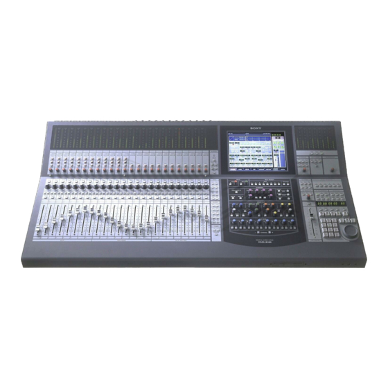
Overview The channel strips The DMX-R100 is a compact digital audio mixer for a The LEDs of the pan controls and faders on the post production house that creates digital media or channel strip allow you to see the analog data at a digital broadcasting. -
Page 9: Connection Examples
Connection Examples Video Post Production For the signal flow, see “Block Diagram” on page 131. Chaper 1 Overview... -
Page 10: Music Production
Connection Examples Music Production Chaper 1 Overview... -
Page 11: Live Recording
Live Recording Chaper 1 Overview... -
Page 12: Locations And Functions Of Parts And Controls
Locations and Functions of Parts and Controls Composition of the Front Panel For details, refer to pages indicated in parentheses. Talk-Back panel (16) Display section (18) Channel Meter panel (13) Analog Head Amplifier panel (13) Master panel (23) Automation Channel Strip panel (14) panel (26) Headphones connector (23) Channel Fader... -
Page 13: Analog Head Amplifier Panel
4 Input B (input selector) button Analog Head Amplifier Panel Selects the input signal connected to the analog head amplifier. When pressed, the IN-B connector (1/4” This panel allows you to select the input circuit of the TRS jack) on the rear panel becomes active. When this analog input signal and their level adjustment. -
Page 14: Channel Strip Panel
Locations and Functions of Parts and Controls Channel Strip Panel Note To select the desired channel, press the ACCESS button corresponding to the desired channel so that the SOLO MODE section ACCESS button lights. The PAGES button on the Assignment panel allows you to switch the channel strip to channels 1 to 24 or channels 25 to 48. - Page 15 For example, the AUX 1 button is lit in the PANS 3 CUT button section, this control operates as control for the send This button is used to cut various signals depending on volume of AUX 1. the signal path selected in the FADERS section in the For detailed information on the Assignment panel, see page Assignment panel.
-
Page 16: Talk-Back Panel
Locations and Functions of Parts and Controls 4 PGM button Talk-Back Panel Press this button so that it lights, to route the talkback signal memorized on the OSC/TALK BACK window to the PGM output. 5 STUDIO button Press this button so that it lights, to route the talkback signal to the studio monitor output. -
Page 17: Assignment Panel
Assignment Panel PANS section The PANS section allows you to select the functions of the pan controls on the Channel strip panel. When all buttons in this section are turned off, the Pan control operates as the pan control of the signal path selected in the FADERS section. -
Page 18: Parameter Setting Panel
Locations and Functions of Parts and Controls 7 Page selectable buttons 5 MTR button Press button (1 - 24) so that it lights, to load settings Press this button so that it lights. The channel faders on (for the meter, WRITE button, pan control, SOLO the Channel strip panel function as the send-volume button, CUT button, ACCESS button and the channel controls for the MTR bus. -
Page 19: Dynamics Section
4 DELAY control INPUT Section and BUS ASSIGN section Adjusts the delay between 0 and 999 milli seconds (at INPUT section the sampling frequency of 48 kHz). This section allows you to adjust the digital input signal. When the signal input is analog, you can adjust BUS ASSIGN section the converted digital signal. - Page 20 Locations and Functions of Parts and Controls 1 DYNAMICS IN button When the ACCESS button of EXPAND/GATE in the Press this button to make the dynamics section active. dynamics access section 2 is pressed: the following The settings on the DYNAMICS section are displayed parameters for the expander and gate can be set.
- Page 21 EQUALIZER section 1 Equalizer IN button ACCESS EQUALIZER FREQ FREQ FREQ FREQ SHELV SHELV LEVEL LEVEL FREQ FREQ LEVEL LEVEL NOTCH 2 Low-cut filter section 6 HF section 4 LMF section 7 High-cut filter section 3 LF section 5 HMF section Controls and buttons in this section are used for the 4 LMF (Low-mid frequency range equalizer) snapshot and dynamic automation.
- Page 22 Locations and Functions of Parts and Controls 7 High-cut filter section To open the EQALIZER/FILTER window FREQ control: Sets the cut-off frequency of the high- directly from the panel cut filter. If the AUTO ZOOM button is lit (ON) in the IN button: Press this button to activate the high-cut MISC SETUP window, the window directly filter.
-
Page 23: Master Panel
Master Panel Master meter/studio monitor/solo mode sections OVER OVER OVER OVER OVER OVER OVER 1 Master meters 2 Master meter buttons SOLO button on the channel STUDIO LS SOLO MODE HEADPHONES strip panel 2T-1 2T-2 SOLO Headphones SETUP CANCEL connector Buttons and controls in this section are not used for the automation 3 STUDIO LS section... - Page 24 Locations and Functions of Parts and Controls 4 SOLO MODE section Control room monitor section and PGM Changes the function of the channel SOLO buttons. bus section SOLO button: When this button is lit, the SOLO buttons on the channel strip panel function as ‘destructive solo’...
- Page 25 2T-2 button: When this button is lit, the signal input to the 2TR IN 2 connector is monitored. PGM button: When this button is lit, the signal of the PGM bus is monitored. AUX button: When this button is lit, the AUX bus selected on the MONITOR window is monitored.
-
Page 26: Automation Panel
Locations and Functions of Parts and Controls Automation Panel SELECT MACHINE TC AUTOMATION SNAPSHOT SAFE TO LINK DELETE SETUP 1 SELECT MACHINE 5 SNAPSHOT TRIM STORE RECALL UNDO buttons buttons 2 TC AUTOMATION buttons HOURS MINUTES SECONDS FRAMES SNAPSHOT 3 Timecode display 6 SNAPSHOT display window window... - Page 27 ABS (absolute value) button: When this button is lit, 4 Timecode input section automation is on and the timecode automation is Selects the contents to be displayed in the timecode executed in ABS mode. display window 3. TRIM button: When this button is lit, automation is LTC button: When this button is lit, the timecode on and the timecode automation data is recalled in the read by the built-in timecode reader is displayed in the...
- Page 28 Locations and Functions of Parts and Controls RECALL button: Press this button so that it lights, to The jog dial can also be used to change data values, for example, by pressing the SET button under the recall the snapshot data or the cue currently displayed SNAPSHOT display window, the dial adjust the on the SNAPSHOT display window depending on the SNAPSHOT number.
-
Page 29: Elements Of The Rear Panel
Elements of the Rear Panel For detailed information on connectors, refer to pages For connection examples, see page 9, for detailed indicated parentheses. information on connectors, see “Specifications” on page 120, and for signal flow, see “Block Diagram” on page 131. -
Page 30: Control Signal Connectors
Locations and Functions of Parts and Controls Control Signal Connectors For connection examples, see page 9, for detailed information on connectors, see “Specifications” on page 120, and for signal flow, see “Block Diagram” on page 131. Control signal connectors (part 1) 1 FOOT SW connector 4 REMOTE connectors 2 TIME CODE connectors... - Page 31 REF WORD IN connector: Inputs the word sync Used for connecting a standard computer’s monitor to signal. repeat the DMX-R100 on board display. 75 Ohm switch: Must be switched correctly. Normally set this switch to ON. When you send the word sync signal to other machines via the type T BNC relay connector, set this switch to OFF.
-
Page 32: Analog Signal Connectors
Locations and Functions of Parts and Controls Analog Signal Connectors For connection examples, see page 9, for detailed information on connectors, see “Specifications” on page 120, and for signal flow, see “Block Diagram” on page 131. Analog Connectors (part 1) PUSH PUSH PUSH... - Page 33 Analog Connectors (part 2) LINE IN PUSH PUSH PUSH PUSH PUSH PUSH PUSH PUSH PUSH PUSH PUSH PUSH 4 LINE IN connectors 2TR IN1 AUX RET 5 AUX RET connectors 6 2TR IN 1 connectors AUX SEND STD MONITOR CR MONITOR 7 PGM connectors 8 PGM connectors 9 AUX SEND connectors...
-
Page 34: Digital Signal Connectors
6. Insert the optional boards here. Connectors 7 and 8 are for AUX-return channel 7 and For details of how to insert these boards, contact your Sony dealer. channel 8. For detailed information on optional boards, see the next page. -
Page 35: Optional Boards
Optional Boards DMBK-R101 8CH Analog Line In Board Inputs balanced analog signals (+4 dBu standard). The input channels are selected on the AUDIO INPUT ROUTING screen. DMBK-R101 PUSH PUSH PUSH PUSH PUSH PUSH PUSH PUSH ANALOG INPUT ( +4dB ) DMBK-R102 8CH Analog Line Out Board Outputs balanced analog signals (+4 dBu standard). - Page 36 DMBK-R105 8CH Insertion board Inputs/outputs unbalanced analog signals (0 dBu You can use only one DMBK-R105 8CH Insertion standard). The insertion point is set on the AUDIO Board in the DMX-R100. OUTPUT ROUTING screen. DMBK-R105 ANALOG INSERTION ( 0dB )
-
Page 37: Menu Structure
Menu Structure The window based operating menus of the DMX- For detailed information on each menu, refer to the pages indicated in parentheses. R100 are organized in the following structure. Menus related to automation (placed on the top bar on the display) •... -
Page 38: Basic Components And Functions Of The Windows
1 TITLE button When you select KEEP, the data in the work area, volatile memory, is saved in the Current Title’s non- “TITLE” is the term used in DMX-R100 for storing volatile memory. and recalling all the mixer’s automation and housekeeping functions for a project. - Page 39 • OFF: Shows the automation is off. In OFF mode, the • SAVE whole display is black. When you select SAVE, the data in the work area is For information on the fader operation and its results in saved in the current title in the flash memory. ABS mode and trim mode, see page 110.
- Page 40 Basic Components and Functions of the Windows • TO NEXT: Return time mode is set to HOLD TO Notes NEXT. • The READY SETUP cannot be turned ON (light • TOP TO END: Return time mode is set to TOP TO yellow) when the timecode is run at PLAY speed END.
- Page 41 • ALL CANCEL: Sets all READY to SAFE modes. If you touch the MASTER DROP IN button while it is • CLOSE: Close the OPTION button menu. light red, this button turns dark red and all controls in automation WRITE are ‘DROPed’ out and return to 6 Automation status, sampling frequency, the READY status.
-
Page 42: Operating The Touch Panel
Basic Components and Functions of the Windows qa SNAPSHOT button Selecting the item Touch this button to open the SNAPSHOT window (page 72). Many functions can be directly switched by button icons on the display. The color of the button icons will qs CUE button change to show their status. - Page 43 Writing data in the automation data Note Automation data written in the unit is cleared when the When READY SETUP button is light yellow power is turned off or the unit is restarted unless you All of the appropriate channel processing controls on perform the KEEP or SAVE operation.
-
Page 44: Menu Windows
Menu Windows CHANNEL Window channel specified by pressing the ACCESS button on To open this window, touch the CHANNEL button on the channel strip. When you operate the controls and the bottom menu bar to open the menu, then select faders, the control moves are displayed on the [CHANNEL]. -
Page 45: Input/Pan/Assign Window
INPUT/PAN/ASSIGN Window To open this window, touch the CHANNEL button on When setting a channel in STEREO or SURROUND the bottom menu bar, then select “INPUT/PAN/ mode, the link settings on the COPY/LINK window ASSIGN.” Or, when the CHANNEL window is turn to active. - Page 46 Menu Windows The REVERSE, L + R and MS DECODE buttons are A L,C,SW,R buttons B Surround PAN ON button active, only when the STEREO button is lit. In STEREO or SURROUND mode, the linking set in the COPY/LINK window turns to active. REVERSE button: When this button is lit, the right C L/R, F/R WRITE and left are swapped.
- Page 47 E SW (sub woofer) GANG button When this button is lit, the sub woofer level is linked with the MTR send level. F Surround pan display/operation area In surround mode, you can set the surround panning in this area. Touch this area, then drag the icon to the desired point.
-
Page 48: Equalizer/Filter Window
Menu Windows EQUALIZER/FILTER Window This window displays the settings on the EQUALIZER To open this window, perform one of the following: section on the Parameter Setting panel of the unit. • Touch the CHANNEL button on the bottom menu If you touch the display window where the numerical bar, then select “EQUALIZER/FILTER.”... -
Page 49: Dynamics Window
5 EQ (equalizer) IN button Note Touch this button to turn on or off the whole Even if the IN button in each equalizer section is lit, the equalizer section. This button is linked to the IN equalizer/filter sections are not turned on if this button button above and to the right of the EQUALIZER is not lit. - Page 50 Menu Windows 8 KEY button 1 Gain reduction meter Touch this button to open the sub menu that allows Displays the gain reduction of both dynamics sections. you to select the key signal for the dynamics processing. 2 Dynamics characteristics LOCAL: Uses its own channel signal as the key Displays the graph of the dynamics gain transfer signal.
-
Page 51: Menu Aux Send Window
qd KNEE button qf Function access buttons This button is effective only when the compressor These buttons have the same function as the ACCESS mode is selected. button and IN button on the DYNAMICS section on Touch this button to open the sub menu. Then select the Parameter Setting panel. - Page 52 Menu Windows 1 Display window 3 PRE (prefader) buttons 1 to 8 Displays the levels of the AUX SEND 1 to 8 busses. Touch the desired button and turns green to indicate The level of the AUX send bus is adjusted using AUX PRE.
-
Page 53: Eq Library And Dyn Library Windows
EQ LIBRARY and DYN LIBRARY Windows To open the EQ LIBRARY (or DYN LIBRARY) As an example of the LIBRARY window, the window, touch the LIBRARY button in the following description is based on the DYN LIBRARY EQUALIZER (or the DYNAMICS) window. window. -
Page 54: Audio Overview Window
Menu Windows AUDIO OVERVIEW Window To open this window, touch the AUDIO button on the This window shows the active/inactive status of the bottom menu bar, then select “OVERVIEW”. equalizer, dynamics, MTR routing and AUX SEND This window allows you to see the settings performed routing. -
Page 55: Audio Fader Window
AUDIO FADER Window To open this window, touch the AUDIO button on the Touching the display of the desired channel opens the bottom menu bar, then select “FADER.” CHANNEL window of the corresponding channel. This window allows you to see the fader levels of channels 1 to 48, the MTR busses, the AUX send busses and the AUX return busses. -
Page 56: Audio Fader/Cut Grouping Window
Menu Windows AUDIO FADER/CUT GROUPING Window group for channels 1 to 48, the MTR busses, the AUX To open this window, touch the AUDIO button on the send busses and the AUX return busses. bottom menu bar, then select “FADER GROUPING.” This window allows you to set the fader group and cut 1 Group selection area 2 Mode button... - Page 57 To assign or remove the channel to or from the group, Setting the VCA fader group proceed as follows. Perform the following operation after step 1 described in “Setting the GANG fader group”. Setting the GANG fader group Touch the mode button corresponding to the group Touch the desired group button.
- Page 58 Menu Windows Setting the CUT group You can set the CUT group with the same operation procedure as the ones for setting the GANG group except that you have to display CUT on the mode button in step 2. The cut group number is displayed on the lower part of the channel button.
-
Page 59: Copy/Link Window
COPY/LINK Window To open this window, perform one of the following: • Touch the AUDIO button on the bottom menu bar, then select “COPY/LINK.” • On the control panel, hold the ACCESS button of the source channel down one second or more. RETURN button 1 STEREO LINKING FUNCTIONS button... - Page 60 Menu Windows LCR long-chained button: When this button is lit, the Copying the setting of the channel L/C/R, LS, and RS channels are linked. Touch the COPY tab on the window. When the chain buttons are lit, the associated channels Select the desired functions to be copied by are linked automatically.
- Page 61 MTR sends can be copied to the MTR send, AUX send or other channel faders. function button selection 5. ZERO section On the DMX-R100, a “Zero” function is provided for CH b MTR section setting the specified values to the desired value. 4 Zero tab When this tab is selected, you can set the “Zero”...
- Page 62 Menu Windows fader level is copied to the MTR or AUX fader. 1-24 and 25-48 buttons: To select the desired source faders 1-24 or 25-48 as a group, touch and light either button. Then, the faders selected are copied to the MTR or AUX faders.
-
Page 63: Audio Input Routing Window
AUDIO INPUT ROUTING Window To open this window, touch the AUDIO button on the bottom menu bar, then select “INPUT ROUTING.” This window allows you to assign the desired input signal to the desired channel. 1 Destination select buttons 2 V button 3 Source select button 2 v button 4 DEFAULT button... - Page 64 Menu Windows The display of the block list buttons corresponding to Resetting the input matrix to the default SLOT 1 to SLOT 4 depends on the board inserted. setting • When the DMBK-R101 is inserted: SLOTxADC1 to Touch the DEFAULT button. •...
-
Page 65: Audio Output Routing Window
AUDIO OUTPUT ROUTING Window To open this window, touch the AUDIO button on the bottom menu bar, then select “OUTPUT ROUTING”. This window allows you to assign the bus output signal to the desired output connector. Block list 4 Output connector select buttons 5 INSERTION buttons 2 V button 1 Bus select button... - Page 66 Menu Windows to derive an extremely accurate level of signal 4 Output connector select buttons processing. For example, a 16 BIT setting is SLOT 1 to 4, AUX SEND 1 to 8, PGM, MONI OUT recommended for making a master tape for a CD, and Selects the output connector to which the bus block is routed.
-
Page 67: Monitor Window
MONITOR Window This window allows you to control and check the To open this window, perform one of the following: settings for monitoring. • Touch the AUDIO button on the bottom menu bar, then select “MONITOR.” • Press the SETUP button on the STUDIO LS section or the CR MONITOR section of the front panel. - Page 68 Menu Windows 4 CUT ENABLE buttons MTR 1 to MTR 8 buttons: When the SURR button is You can cut the monitor signal by touching the CUT set to ON, you can monitor the surround sound buttons in the CR MONITOR, STUDIO LS section on mixer’s output from the MTR busses 1 to 6.
- Page 69 B ALT/MOM (alternate/momentary) button Note This button works for both the studio and the control In DMX-R100, the SOLO mode is the listening mode monitor signals. which cuts all other channels. So SOLO affects the Selects the operation of the SOLO button of each monitor and other mixer outputs.
-
Page 70: Osc/Talkback Window
Menu Windows OSC/TALKBACK Window To open this window, perform one of the following: This window allows you to operate oscillators and • Touch the AUDIO button on the bottom menu bar, talkback functions. then select “OSC/TALKBACK”. • Press the SETUP button on the Talkback panel on the unit. - Page 71 5 Output select buttons Touch the corresponding button to select the desired signal path for the oscillator signal. 6 FREQUENCY dial and GANG button L /R dials: Touch the dial so that you can set the frequency of the L or R oscillator signal using the jog dial on the unit.
-
Page 72: Snapshot Window
Menu Windows SNAPSHOT Window To open this window, perform one of the following: This window allows you to control and monitor the • Touch the SNAPSHOT button on the bottom menu snapshot automation. For detailed information on snapshot automation, see page bar. - Page 73 4 NEW button • Fader grouping Touch this button to store the current mixer settings as • Output routing a new snapshot data. • Monitor signal settings The lowest unused number is used for the new • Oscillator/talkback signal settings snapshot and it is temporarily named “# + xx”...
-
Page 74: Cue Window
Menu Windows CUE Window To open this window, touch the CUE button on the bottom menu bar. This window allows you to control the cue function. For detailed information on cue operation, see page 106. 5 NEW button 8 RECALL button TIME CODE button 9 UNDO button 6 STORE button... - Page 75 SET 2 CUES button: When this button is ON and 7 DELETE button you select two cues, the unit displays them on the Touch this button to delete the selected cue point from MACHINE CONTROL window. The earlier timecode the CUE list 0. cue is assigned to the LOCATE TIME, and the larger If the event is linked with the cue point, the event is number timecode is assigned to the CYCLE END.
- Page 76 Menu Windows qs EVENT buttons Touch the desired button to open the menu list of the events that can be TC linked. SNAPSHOT: Links a snapshot. EQ LIB (equalizer library) and DYN LIB (dynamics library): Specify the channel which the library affects.
-
Page 77: Automation Window
AUTOMATION Window For detailed information on automation, see page 108. To open this window, touch the AUTOMATION button on the bottom menu bar. This window allows you to control aspects of the dynamic automation. 6 MAKE STATIC tab 5 AUTOMATION ISOLATE tab 1 FREE MEMORY display 2 A/B BUFFER ROTATION 7 CHANNEL... - Page 78 Menu Windows A Automation return mode button AUTO button: Touch this button to enable the Touch this button to select the mode that returns to the PUNCH IN TIME/PUNCH OUT TIME display previous data. windows. When this button is not selected, automation BUTT: Returns to the previous data as a “jump”...
- Page 79 Touch the OFF LINE button. The dialog appears for confirmation, and then off line is executed. In the duration between the punch-in/-out points, the dropped-in item data is overwritten by the new data in step 7. Note The AUTO RETURN TIME setting is ignored. 5 AUTOMATION ISOLATE tab Selects the channels or functions that you want to isolate from automation replay.
-
Page 80: Machine Control Window
This window allows you to set up the mixer to control using this unit. Only one machine can be controlled at devices that use MIDI machine control (MMC), Sony any one time, but the mixer can be quickly re- 9-pin and timecode chase. - Page 81 5 LOCATE TIME display window and 8 ALL STOP button CAPTURE button Touch this button to issue the stop command to all of Displays the time the machine locates to. the machine control ports. Touching the display allows you to enter the locate time using the ten key pad.
-
Page 82: Title Manager Window
8 FDD OPERATION buttons 9 CURRENT TITLE CLEAR button 0 INFORMATION section In the DMX-R100, data related to a project (snapshot 1 Title list data, automation data, library data, settings for Displays the list of titles stored in the media selected sampling frequency, timecode mode, etc.) is called... - Page 83 Touch this button to store the current title in the • The unit only accepts a 2 HD floppy disk, formatted unused title number that is the lowest one. in the DMX-R100 format or the DOS format. Disks other than the above are not acceptable. 3 SAVE button •...
- Page 84 (CUE 1) from which automation starts. floppy disk inserted in the floppy disk drive in the TC MODE row: Displays the mode of the timecode DMX-R100 format. All data stored on the disk is to be used in automation. erased. The title list becomes blank.
-
Page 85: Midi Window
MIDI Window the MIDI channels, program change-snapshot To open this window, touch the SYSTEM button on configuration, mixer event-control change the bottom menu bar, then select “MIDI” on the menu. configuration and the settings of the PC ports. This window allows you to perform the assignment of 4 PC PORT 1 MIDI CHANNEL section MODE... -
Page 86: Sync/Time Code Window
Menu Windows SYNC/TIME CODE Window To open this window, touch the SYSTEM button on This window allows you to control the settings of the the bottom menu bar, then select “TIME CODE” on reference signal and the timecodes used for the menu. - Page 87 When this button is selected, external digital audio signal is being input. equipment must be synchronized with the DMX-R100 that is the sync master. Chapter 3 Menu...
- Page 88 Menu Windows A MODE button NO VIDEO: The video signal is not being received. Check the setting of the termination resistor or Displays and selects the mode of the timecode to be used for automation. whether the correct video signal is being received. The timecode generator works according to the –...
- Page 89 7 TIME CODE GENERATOR section • To avoid the automation interruption when the timecode goes over “00:00:00:00”, enter an offset of an hour unit. A MODE button • To manipulate the multiple materials, which have the same timecode, in one title automation, enter an B PRESET button offset of an hour unit.
- Page 90 Menu Windows B PRESET button Touch this button to set ON. You can enter and display the preset time on the PRESET/GENERATE TIME display window. When the LOCAL mode is selected, touching START will generate timecode from the preset time. Enter the timecode using a keyboard connected to the unit or the 10 keypad after touching the PRESET/ GENERATE TIME display window to highlight it.
-
Page 91: I/O Status Window
I/O STATUS Window To open this window, touch the SYSTEM button on the bottom menu bar, then select the I/O STATUS on the menu. This window allows you to check the performance of the digital audio input/output. 1 SLOT 1 to 4 section 2 DA 88 button 3 BUILD-IN DIGITAL I/O section 4 INFORMATION section... - Page 92 INFORMATION 88 inserted into the slot, it is necessary to replace the section 4. ROM in the DMBK-R107 slot. Contact your Sony The content of the display is as follows: dealer. • RDY (ready)
- Page 93 • FS NORMAL: Indicates that they are correctly Displays the sampling frequency of the digital audio synchronized. signal. SLIP: Asynchronization causes interpolation or • ORIGIN cropping of data. This results in noise or distortion. Displays the ORIGIN information written in the Check that the unit synchronizes with each unit channel status of the AES/EBU digital audio signal in correctly.
-
Page 94: Misc Setup Window
Menu Windows MISC SETUP Window To open this window, touch the SYSTEM button on This window allows you to control and check settings the bottom menu bar, then select “MISC SETUP” on for the system’s clock, the channel meter display, the the menu. - Page 95 PRE (prefader) button: Selects the signal of the point By using the – key or the jog dial, decrease the located before the CUT switch of the input signal path. sensitivity until “TOUCH” appears in white. PST (post fader) button: Selects the signal of the Be care not to touch a fader while performing point located before the pan of the input signal path.
- Page 96 Menu Windows To calibrate the touch panel, proceed as follows: 8 FADER CAL. (fader calibration) button With this button lit, a dialogue opens to calibrate the Turn off the power and connect a mouse to the fader position. MOUSE connector on the rear panel. Then turn on the power again.
-
Page 97: Keyboard Window
With the button lit, a fader holds the drop in status, You can switch the TOUCH HOLD button on/off by and “TH” appears in the AUTO box on the top menu selecting TOUCH HOLD from the AUTO button bar. menu, too. KEYBOARD Window To open this window, touch the row or box which STATUS window. -
Page 98: For System Setup
For System Setup Changing the Keyboard Type Updating the DMX-R100 Version The DMX-R100 is factory-preset for use with a The update kit for Version 2.0 consists of two disks: Japanese type keyboard. Select the desired keyboard “SYSTEM UPDATE 2.0” and “APPLICATION UPDATE 2.0.”... - Page 99 The start-up window opens. When the DMX-R100 system is updated, the message “Update for XXXX completed. Remove your floppy disk and press any key...” appears.
-
Page 100: Memory Structure And Title
Memory Structure and Title Structure of Snapshot and Automation Memory Floppy disk Title config Library Saved into the floppy disk Loaded from the floppy Snapshot disk Automation SAVE (or SAVE Buffer A or B AS NEW) LOAD Title #10 Dynamic RAM Current title Title #1 Library... -
Page 101: About Titles
When you use the unit for first time (with the About Titles default setting) or there are no current files The current title is created with the following settings. In operating the unit, data such as snapshots, dynamic • Sampling frequency: 48 kHz automation data, sampling frequencies and timecode •... -
Page 102: Basic Operation Procedure
Basic Operation Procedure Basic Mixer Operation Flow from Turning On to Monitoring The basic mixer operation is explained in the From the right column following operation flow chart. Example: In the following flow chart, audio from the Routing the output signal microphone connected to the IN A connector is routed to CH 1 and the fader is used as a channel fader. - Page 103 From the previous page Using the stereo signal Setting the channel When setting PAN of the channel to OFF • Press the ACCESS button on the channel Display “STEREO” on the MODE button by strip panel (page 14) for CH 1 on the unit so touching it on the INPUT/PAN/ASSIGN window that the button lights up.
-
Page 104: Snapshot Automation Procedure
Basic Operation Procedure Snapshot Automation Procedure Using the ten key pad, enter the number of the snapshot that you want to store. The unit can memorize up to 99 control settings Press the STORE button. (snapshots). It is located within the SNAPSHOT buttons By linking the stored snapshot settings with the section. -
Page 105: Library Operation Procedure
To recall the snapshot data in the window Library Operation Procedure Open the SNAPSHOT window. The unit can memorize up to 99 equalizer settings and up to 99 dynamics settings as library entries. Touch the number for the snapshot data that you Use the stored libraries as described below;... -
Page 106: Cue Operation Procedure
Basic Operation Procedure To perform the cue operation by manipulating buttons Recalling a library entry and controls on the unit, use the SNAPSHOT SET Open the EQUALIZER/FILTER (or DYNAMICS) buttons and the ten key pad on the Automation panel window. of the unit. - Page 107 To store the cue point in the CUE window Changing the event data linked with a cue point Open the CUE window. Open the CUE window. Touch the NEW button. At this time, if there are no cue points registered on Touch the EVENT display for the cue point that the cue list, CUE 2 is created.
-
Page 108: Automation Procedures
Basic Operation Procedure Change the settings so that automation operates to Automation Procedures write and recall automation data. 1 Touch the ABS button on the Automation Do not set controls for both snapshot and dynamic panel to select ABS mode. automation. - Page 109 Drop out the automation data using one of the When you drop in by touching the numerical value following methods. displayed on the window, you can drop out using one • Touch the MASTER DROP IN button on the of the following methods: window to turn its color to dark red.
- Page 110 Basic Operation Procedure Fader operation and its results The following figures show the fader operation and the results In the figures, the fader operations are indicated using the of the fader operation. following lines: : Indicates the data stored last time (previous data) : Indicates the actual results of the fader operation When operating the faders in ABS mode (new data).
- Page 111 To update in TRIM mode In TRIM mode, you can update previous automation ON/OFF of the CUT button: data by adding offsets. When the TRIM mode is specified, all faders automatically move to the 0 dB point, and the Press Release difference between the fader point and the 0 dB point Cut data previsouly stored.
-
Page 112: Using The Automation Isolate Function
Basic Operation Procedure Using the WRITE HOLD Mode Using the Automation Isolate and the TOUCH HOLD Mode Function The automation isolate function allows you to remove Using the WRITE HOLD mode automation control from a selected channel or function. Using this automation isolate function, you When the WRITE HOLD mode is set to ON, controls can manually adjust the level, regardless of the stored are prohibited from dropping out and are held in... -
Page 113: Punching In/Punching Out
Set the SAFE button to OFF after adjusting the Punching In/Punching Out level to a new setting. Start the tape recorder in PLAY. Punching in/punching out by specifying the durations Store the required duration time by setting the punch in and punch out times. You can change automation data between specified You can drop out manually if preferred. -
Page 114: Using The Audition Mode
Basic Operation Procedure Set the foot switch to ON at the desired time. During the duration specified by the punch in/out function, the minimum level is stored as automation Stop the tape recorder at the right point, or switch data for the corresponding fader. the foot switch to OFF. -
Page 115: Using The Write Now Function
Example 1: Removing noise To store data in AUDITION mode, perform either of the following. Set the AUTOMATION mode to ABS. • Stop the tape at the desired point while the SAFE button is set to OFF. Touch the AUTO button in the PUNCH IN/OUT In this case, after passing the frames specified by the AUTO RETURN TIME setting, the data section in the AUTOMATION window. -
Page 116: Data Connection When Using The Foot Sw Mode Or The Audition Mode
Basic Operation Procedure Touch the WRITE NOW button on the Automation data when the timecode AUTOMATION window, and touch “EXECUTE” is stopped before punching out in the dialogue. In TOP TO END mode Data Connection When Using the Punch in with the use of the foot switch or SAFE button. FOOT SW Mode or the AUDITION Drop in the item and manipulate it. -
Page 117: Dialogues On The Window
Dialogues on the Window In the following cases, a dialogue box appears on the window to confirm the operation and indicate the status of the unit. Selecting the [YES] or [CANCEL] button on the box gives the result shown in parenthesis. Cases Dialogues and remedies “Are you sure you want to delete the selected snapshot?.”... - Page 118 Dialogues on the Window Cases Dialogues and remedies The title files are corrupted. “Corrupted title files. Do you want to initialize all titles?” [YES] (The corrupted title files are deleted.) The storage space is insufficient to save the current title. “Insufficient storage space.
- Page 119 Cases Dialogues and remedies The tape recorder does not start operation “Switching MIDI Machine Control to OPEN LOOP.” even though 2 seconds have elapsed [OK] (Switched in open loop control mode.) when MIDI controlling the tape recorder. “Are you sure you want to copy automation data? When you copy data between the buffers A and B: Destination buffer will be overwritten”...
-
Page 120: Appendix
Specifications Input/Output Connectors Digital audio input/output Digital input connectors Connector Number of inputs Number of channels Connector type Signal format ×2 ×4 AUX RET 5/6, 7/8 XLR-3-31 AES/EBU ×1 Stereo ×2 2TR IN 2 XLR-3-31 AES/EBU Digital output connectors Connector Number of outputs Number of channels Connector type Signal format... - Page 121 TIME CODE input/output XLR-3-32, Balanced/XLR-3-31, SMPTE/EBU Balanced MIDI DIN 5-pin, female MIDI standard THRU REMOTE D-sub 9-pin, female Sony 9-pin OUT 1, OUT 2 PC PORT Mini DIN 8-pin, female FOOT SW Phone jack Make-point MOUSE Mini DIN 6-pin, female PS/2...
-
Page 122: Audio Characteristics
Specifications Audio Characteristics Signal processing characteristics Characteristics Specification 32/40 bit floating point Signal processing Frequency range High frequency range : 622 Hz to 19.9 kHz (61 points) Equalizer : 622 Hz to 39.8 kHz (73 points) Response adjustable range ±20 dB (128 points, 0.25 to 0.5 dB step) 0.5 to 16 (63 points) Type Shelving/Peaking switchable... -
Page 123: Automation Function
Another audio characteristics Specifications Characteristics Frequency response Line input (LINE IN to PGM OUT) 20 Hz to 20 kHz, ±0.2 dB Mic input (MIC IN to PGM OUT) 20 Hz to 20 kHz, ±0.3 dB Harmonic distortion Line input (LINE IN to PGM OUT) 0.01 %, at + 4 dBs, 1 kHz Mic input (MIC IN to PGM OUT) 0.1 %, at - 60 dBs, 1 kHz... -
Page 124: Others
Specifications Others Power requirements DMX-R100 (UC): AC120 V, 60 Hz DMX-R100 (CE): AC 220 to 240 V -, 50/60 Hz Power consumption 200 W Peak inrush current (1) Power ON, current probe method: 1135 50 A (240V) 1197 (2) Hot switching inrush current,... -
Page 125: Midi
MIDI MIDI Implementation Chart Function Transmitted Recognized Remarks Basic: At power on 1 to 16, OFF 1 to 16, OFF Memorized after the power off. Channel: Assignable 1 to 16, OFF 1 to 16, OFF × × Mode: At power on ×... -
Page 126: Control Change Table
MIDI Control Change Table Parameter Mode 1 Mode 2 Parameter Mode 1 Mode 2 change No. Function change No. Function Function Function —— —— CH39 Fader AUX8 MASTER Fader CH1 Fader CH1 Fader CH40 Fader AUX RET1 Fader CH2 Fader CH2 Fader CH41 Fader AUX RET2 Fade... - Page 127 Parameter Mode 1 Mode 2 Parameter Mode 1 Mode 2 change No. Function change No. Function Function Function CH6 PAN CH7 CUT CH30 PAN AUX RET7 CUT CH7 PAN CH8 CUT CH31 PAN AUX RET8 CUT CH8 PAN CH9 CUT CH32 PAN CH1 AUX1 SEND CH9 PAN...
-
Page 128: Index
Index B, C Basic operation flow ....102 Analog head amplifier Data connection using the FOOT Analog head amplifier Buffer SW mode or AUDITION Buffer A/B ....27, 100 panel ....... 13 mode ........116 Copying data between Buffer A Setting operation flow .. - Page 129 MACHINE CONTROL Keyboard window ......80 Changing the keyboard MIDI window ...... 85 PAGEs section ......18 type ......... 98 MISC SETUP window ..94 PAGE button on the KEYBOARD window ..97 MONITOR window .... 67 window ......54 OSC/TALKBACK Pages selectable buttons ..
- Page 130 Touch panel Digital audio Calibrating ......96 input/output ....120 Operating the touch panel ..42 Signal processing Updating the DMX-R100 characteristics ....122 Application ......99 Stereo Console ........ 99 STEREO link ....... 45 Notes on updating ....98 Using the stereo signal ..
-
Page 131: Block Diagram
Block Diagram Fs = 44.1/48 kHz (1 fs) Appendix... - Page 132 Block Diagram Fs = 88.2/96 kHz (2 fs) Appendix...
- Page 134 Sony Corporation Printed in Japan...