Sony CDP-CX200 Service Manual
Hide thumbs
Also See for CDP-CX200:
- Operating instructions manual (19 pages) ,
- Operating instructions manual (20 pages)
Table of Contents
Advertisement
SERVICE MANUAL
MICROFILM
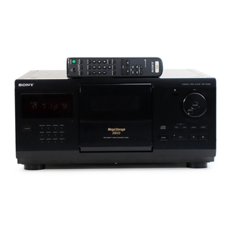
CDP-CX200
Model Name Using Similar Mechanism
CD Mechanism Type
Base Unit Type
Optical Pick-up Type
SPECIFICATIONS
USA, Canada
Europe and Singapore
E, PX
Australia
— 1 —
US Model
Canadian Model
AEP Model
UK Model
Australian Model
PX Model
NEW
CDM-40
KSM-213BKN/M-N
KSS-213B/S-N
120V AC, 60Hz
220V - 230V AC, 50Hz
240V AC, 50Hz
COMPACT DISC PLAYER
E Model
Advertisement
Table of Contents

Related Manuals for Sony CDP-CX200


Summary of Contents for Sony CDP-CX200
- Page 1 CDP-CX200 SERVICE MANUAL US Model Canadian Model AEP Model UK Model E Model Australian Model PX Model Model Name Using Similar Mechanism CD Mechanism Type CDM-40 Base Unit Type KSM-213BKN/M-N Optical Pick-up Type KSS-213B/S-N SPECIFICATIONS USA, Canada 120V AC, 60Hz...
-
Page 2: Table Of Contents
MODEL IDENTIFICATION TABLE OF CONTENTS — BACK PANEL — 1. SERVICING NOTE ............3 2. GENERAL ..............3. DISASSEMBLY 3-1. Front Panel Assembly ............9 3-2. Back Panel Assembly ............9 4-982-790- 3-3. Table Assembly ..............10 3-4. Mechanism Deck Assembly ..........10 US Model : 0π... -
Page 3: Servicing Note
REPLACE THESE COMPONENTS WITH SONY PARTS FONCTIONNEMENT. NE REMPLACER CES COMPOSANTS WHOSE PART NUMBERS APPEAR AS SHOWN IN THIS QUE PAR DES PIÈCES SONY DONT LES NUMÉROS MANUAL OR IN SUPPLEMENTS PUBLISHED BY SONY. SONT DONNÉS DANS CE MANUEL OU DANS LES SUPPLÉMENTS PUBLIÉS PAR SONY. -
Page 4: General
SECTION 2 GENERAL LOCATION OF PARTS AND CONTROLS Front Panel 1 23 4 56 !º !¡!™ !• !∞ !¢ !¶ !§ !£ 1 POWER button !¡ CHECK button 2 CONTINUE button !™ CLEAR button 3 Display window !£ p (stop) button 4 SHUFFLE button !¢... - Page 5 This section is extracted from instruction manual. — 5 —...
- Page 6 — 6 —...
- Page 7 — 7 —...
- Page 8 — 8 —...
-
Page 9: Disassembly
SECTION 3 DISASSEMBLY Note : Follow the disassembly procedure in the numerical order given. 3-1. FRONT PANEL ASSEMBLY 6 Remove the claw 1 Two screws (BVTP 3x8) 7 Front panel assembly 5 Remove the claw 3 Two screws (BVTT 3x6) 4 Flat type wire (CN601) 2 Three screws (BVTT 3x6) 3-2. -
Page 10: Table Assembly
3-3. TABLE ASSEMBLY 4 Three screws (BVTT3x6) 1 Stop ring (E type) 5 Three holder assemblies 6 Table assembly 7 Washer 2 Two screws (BVTT3x6) 3 Two holder assemblies 3-4. MECHANISM DECK ASSEMBLY 6 Flat type wire !º Mechanism deck (23core) (CN303) Main board 1 Four screws (BVTT3x6) -
Page 11: Base Unit Assembly
3-5. BASE UNIT ASSEMBLY 1 Screw (BVTT3x6) 2 Fulcrum plate (BU UPPER) assy 3 Base unit — 11 —... -
Page 12: Test Mode
SECTION 4 TEST MODE 4-1. Display Check Mode 4-3. Key and Display Check Mode With the power turned off (standby state), press the POWER button To set this mode, connect the test point (TP302:AFADJ) on the MAIN while pressing the P (pause) button. board to Ground, and turn on the power supply plug to the outlet. -
Page 13: Adjustments
SECTION 5 ADJUSTMENTS 5-1. MECHANICAL ADJUSTMENT Perform the following steps before carrying out adjustments. 1. Turn ON the power of the unit, set disc to disc table No. 92, and perform chucking. 2. Turn OFF the power. 3. Remove the case. 4. - Page 14 SENSOR ALIGNMENT If the disc table swings to the left and right just before the disc is chucked, perform the following adjustment. LEVER (stopper) assembly (1)Rotate the cam and adjust to the position Bracket (sensor) shown in the figure. Table assembly (2) Check that the lever (stopper) assem- bly secures the disc table as shown in the figure.
- Page 15 GUIDE (DISC T) ALIGNMENT Holder (guide T) Guide (disc T) Fixed screw (1) Rotate the cam and adjust to the position shown in the figure. Guide (disc T) (2) Check that the state is as shown in the figure. Disc Tapering screwdriver Guide (disc T) Disc...
- Page 16 HOLDER (DISC A) ALIGNMENT Holder (disc A) Thrust screw (1) Rotate the cam and adjust to the position shown in the figure. Disc 0–1 mm Holder (disc A) (2)Check that the state is as shown in the figure. Disc Holder (disc A) Thrust screw 1 2 3 4 1 2 3 4...
- Page 17 PULLY AND DISC CENTER HOLE ALIGNMENT Base unit Bracket (BU adjustment) (1) Rotate the cam and adjust to the position shown in the figure. Magnet assembly (2)Check that the state is as shown in the figure. 0.5–2mm Disc Disc pulley Disc hole Base unit Note:The disc should not be fixed.
- Page 18 MAGNET ASSY ALIGNMENT Adjustment screw Magnet assy (1) Rotate the cam and adjust to the posi- tion shown in the figure. Disc Magnet holder Magnet assy Adjustment screw 1 2 3 4 (3)Apply screw-lock to the part after adjusting. 1 2 3 4 Adjustment screw (2)Rotate the adjustment screw until A=B or between A:B=2:1...
-
Page 19: Electrical Block Checking
5-2. ELECTRICAL BLOCK CHECKING Note: Note: A clear RF signal waveform means that the shape “◊” can be 1. CD Block is basically designed to operate without adjustment. clearly distinguished at the center of the waveform. Therefore, check each item in order given. 2. - Page 20 RF PLL Free-run Frequency Check Procedure : 1. Connect frequency counter to test point TP (PLCK) with lead wire. frequency counter BD board TP (PLCK) 2. Turn Power switch on. 3. Put the disc (YEDS-18) in to play the number five track. Confirm that reading on frequency counter is 4.3218MHz.
-
Page 21: Diagrams
SECTION 6 DIAGRAMS 6-1. CIRCUIT BOARDS LOCATION LUMINOUS board MAIN board T. SENS board ILLUMINATION board JACK board DISP board T. MOTOR board DOOR SW board RAY-CATCHER board JOG board BD board L.SW board L. MOTOR board — 21 —... -
Page 22: Ic Pin Function
6-2. IC PIN FUNCTIONS • IC101 DIGITAL SERVO, DIGITAL SIGNAL PROCESSOR (CXD2545Q) Pin No. Pin Name Function SRON Sled drive output (Open) SRDR Sled drive output SFON Sled drive output (Open) TFDR Tracking drive output TRON Tracking drive output (Open) TRDR Tracking drive output TFON... - Page 23 Pin No. Pin Name Function – Digital power supply ASYE Asymmetry circuit ON/OFF (Connected to +5V) PSSL Audio data output mode selection input (Connected to Ground) WDCK 48-bit slot D/A interface. Word clock. (Open) LRCK 48-bit slot D/A interface. LR clock. DATA DA 16 output when PSSL=1.48-bit slot serial data when PSSL=0 BCLK...
- Page 24 Pin No. Pin Name Function XRST System reset DIRC Used in 1-track jump mode (Connected to +5v) SCLK SENS serial data read-out clock DFSW Defect selection pin (Connected to Ground) ATSK Input pin for anti-shock (Connected to Ground) DATA Serial data input, supplied from CPU XLAT Latch input, supplied from CPU CLOK...
-
Page 25: Ic303 System Control (Cxp84332-Q28Q)
• IC303 SYSTEM CONTROL (CXD84332-028Q) Pin No. Pin Name Function Open Open Open Open Open Open Open Open Open Open Open Open Open LED1 PLAY LED control H: Lighting up LED2 PAUSE LED control L: Lighting up LED 3 POWER standby LED conteol L: Lighting up DOOR SW Front foor switch... - Page 26 Pin No. Pin Name Function KEY2 Key input KEY1 Key input KEY0 Key input Latch for servo IC AFADJ ADJ Test mode input. BUSIN CONTROL-A1 input L: Active PRGLT Latch for digital filter IC Clock for servo IC and digital filter IC AMUTE Audio mute H: Mute ON...
-
Page 33: Exploded Views
SECTION 7 EXPLODED VIEWS NOTE: The components identified by • Abbreviation • Items marked “*” are not stocked since they are mark ! or dotted line with mark CND : Canadian model seldom required for routine service. Some delay ! are critical for safety. : German model should be anticipated when ordering these items. -
Page 34: Disc Table Section
7-2. DISC TABLE SECTION not supplied supplied not supplied not supplied not supplied supplied not supplied supplied M801 supplied supplied Ref. No. Part No. Description Remark Ref. No. Part No. Description Remark 4-983-279-01 CUSHION (RF) * 51 1-661-466-11 T. MOTOR BOARD * 67 4-982-804-01 COVER (DISC) X-4947-230-1 BRACKET (TABLE) ASSY... -
Page 35: Front Panel Section
4-982-783-01 LEVER (WINDMILL) 4-977-593-11 RING (DIA. 50), ORNAMENTAL (EXCEPT US,CND) 4-933-134-01 SCREW (+PTPWH M2.6X6) 4-977-358-11 CUSHION (8X12.5) 4-982-785-01 SPRING (OPEN), COMPRESSION 4-963-404-21 EMBLEM (5-A), SONY 4-982-784-01 LEVER (LOCK) X-4947-219-1 PLATE (A) ASSY, FULCRUM * 129 A-4699-036-A JOG BOARD, COMPLETE 4-982-799-01 CUSHION (STOPPER) 4-951-620-01 SCREW (2.6X8), +BVTP... -
Page 36: Mechanism Section-1 (Cdm-40)
7-4. MECHANISM SECTION-1 (CDM-40) not supplied not supplied not supplied not supplied Ref. No. Part No. Description Remark Ref. No. Part No. Description Remark FL701 1-517-517-11 INDICATOR TUBE, FLUORESCENT A-4672-092-A MAGNET ASSY X-4947-241-1 LEVER (C) ASSY 3-366-559-02 MAGNET (CHUCK) 4-982-882-01 SPRING (LIMITTER), TORSION 4-960-633-01 YOKE (MAGNET) 4-982-881-01 SPRING (HOLDER), TORSION X-4947-239-1 LIMITTER (A) ASSY... -
Page 37: Mechanism Section-2 (Cdm-40)
7-5. MECHANISM SECTION-2 (CDM-40) not supplied not supplied not supplied M802 Ref. No. Part No. Description Remark Ref. No. Part No. Description Remark 4-976-465-01 GEAR (LOADING 1) 4-951-291-01 SCREW 4-976-466-01 GEAR (LOADING 2) X-4947-234-1 SLIDER (LOCK) ASSY 4-982-893-01 GEAR (CENTER 2) 4-982-857-01 BEARING (CAM) X-4947-607-1 GEAR (PULLEY) ASSY 4-982-860-01 CAM (A) -
Page 38: Base Unit Section-1 (Ksm-213Bkn/M-N)
7-6. BASE UNIT SECTION-1 (KSM-213BKN/M-N) Ref. No. Part No. Description Remark Ref. No. Part No. Description Remark 3-356-601-11 SCREW, STEP 4-982-872-01 SPRING (F-2), TENSION X-4947-244-1 SLIDER (BU ADJUSTMENT) ASSY 4-982-871-01 SPRING (F-1), TENSION X-4947-243-1 HOLDER (BU) ASSY 4-982-858-01 DAMPER 4-982-859-01 HOLDER (DAMPER) 4-960-617-01 CAP (F) 4-982-878-01 SPRING (F), COMPRESSION —... -
Page 39: Base Unit Section-2 (Ksm-213Bkn/M-N)
7-7. BASE UNIT SECTION-2 (KSM-213 BKN/M-N) not supplied not supplied not supplied M101 not supplied M102 The components identified by mark ! or dotted line with mark ! are critical for safety. Replace only with part number specified. Les composants identifiés par une marque ! sont critiques pour la sécurité. -
Page 40: Electrical Parts List
SECTION 8 ELECTRICAL PARTS LIST Note: • Due to standardization, replacements in the parts list • SEMICONDUCTORS The components identified by may be different from the parts specified in the dia- In each case, u: µ , for example: mark ! or dotted line with mark grams or the components used on the set. - Page 41 JACK DISP ILLUMINATION DOOR SW Ref. No. Part No. Description Remark Ref. No. Part No. Description Remark R162 1-216-101-00 METAL CHIP 150K 1/10W S702 1-572-184-11 SWITCH, TACTILE (CONTINUE)) S703 1-572-184-11 SWITCH, TACTILE (SHUFFLE) < SWITCH > S704 1-572-184-11 SWITCH, TACTILE (PROGRAM) S705 1-572-184-11 SWITCH, TACTILE (REPEAT) S101...
- Page 42 JACK L.MOTOR L.SW Ref. No. Part No. Description Remark Ref. No. Part No. Description Remark < CONNECTOR > < DIODE > CN501 1-770-724-11 CONNECTOR, BOARD TO BOARD 9P D601 8-719-301-49 DIODE SEL2810A-CD (P) CN502 1-770-724-11 CONNECTOR, BOARD TO BOARD 9P D602 8-719-303-02 DIODE SEL2510C-D (·) CN503...
- Page 43 LUMINOUS MAIN Ref. No. Part No. Description Remark Ref. No. Part No. Description Remark 1-661-468-11 LUMINOUS BOARD C333 1-126-052-11 ELECT 100uF ************** C334 1-164-159-11 CERAMIC 0.1uF 4-976-473-01 HOLDER (LED-S) C335 1-164-159-11 CERAMIC 0.1uF C336 1-162-198-31 CERAMIC 8.2PF < DIODE > C337 1-162-198-31 CERAMIC 8.2PF...
- Page 44 MAIN Ref. No. Part No. Description Remark Ref. No. Part No. Description Remark < COIL > R311 1-247-843-11 CARBON 3.3K 1/4W R312 1-249-429-11 CARBON 1/4W L304 1-412-297-11 INDUCTOR 3.3uH R316 1-249-429-11 CARBON 1/4W R317 1-249-429-11 CARBON 1/4W < TRANSISTOR > R318 1-249-429-11 CARBON 1/4W...
- Page 45 MAIN RAY-CATCHER T.MOTOR T.SENS Ref. No. Part No. Description Remark Ref. No. Part No. Description Remark < VIBRATOR > ! CNP901 1-696-845-11 CORD, POWER (AUS) ! CNP901 1-751-529-11 CORD, POWER (UK) X301 1-579-175-11 VIBRATOR, CERAMIC (10MHz) X302 1-767-155-11 VIBRATOR, CRYSTAL (33.8688MHz) FL701 1-517-517-11 INDICATOR TUBE, FLUORESCENT M101...
- Page 46 Ref. No. Part No. Description Remark ************* HARDWARE LIST ************* 7-685-646-79 SCREW +BVTP 3X8 TYPE2 N-S 7-685-871-01 SCREW +BVTT 3X6 (S) 7-685-647-79 SCREW +BVTP 3X10 TYPE2 N-S 7-685-534-19 SCREW +BTP 2.6X8 TYPE2 N-S 7-685-871-09 SCREW +BVTT 3X6 (S) 7-682-947-01 SCREW +PSW 3X6 7-682-548-04 SCREW +BVTT 3X8 (S) 7-624-111-04 STOP RING 7.0, TYPE -E 7-624-106-04 STOP RING 3.0, TYPE -E...
- Page 47 CDP-CX200 English 96G0992-1 Printed in Japan Sony Corporation © 1996.7 9-960-723-11 Home A&V Products Company Published by Quality Engineering Dept. (Shibaura) — 64 —...