Acer Aspire L310 Service Manual
Acer pc
Hide thumbs
Also See for Aspire L310:
- Guía del usuario (43 pages) ,
- Manuel d'utilisation (41 pages) ,
- Manual do utilizador (41 pages)

Related Manuals for Acer Aspire L310


Summary of Contents for Acer Aspire L310
- Page 1 AcerPower 2000/Aspire L310 Service Guide Service guide files and updates are available on the AIPG/CSD web; for more information, please refer to http://csd.acer.com.tw PRINTED IN TAIWAN...
-
Page 2: Revision History
Revision History Please refer to the table below for the updates made on AcerPower 2000/Aspire L310 service guide. Date Chapter Updates... - Page 3 Copyright Copyright © 2006 by Acer Incorporated. All rights reserved. No part of this publication may be reproduced, transmitted, transcribed, stored in a retrieval system, or translated into any language or computer language, in any form or by any means, electronic, mechanical, magnetic, optical, chemical, manual or otherwise, without...
- Page 4 Any Acer Incorporated software described in this manual is sold or licensed "as is". Should the programs prove defective following their purchase, the buyer (and not Acer Incorporated, its distributor, or its dealer) assumes the entire cost of all necessary servicing, repair, and any incidental or consequential damages resulting from any defect in the software.
- Page 5 Conventions The following conventions are used in this manual: Screen messages Denotes actual messages that appear on screen. NOTE Gives bits and pieces of additional information related to the current topic. WARNING Alerts you to any damage that might result from doing or not doing specific actions.
- Page 6 DIFFERENT part number code to those given in the FRU list of this printed Service Guide. You MUST use the list provided by your regional Acer office to order FRU parts for repair and service of customer machines.
-
Page 7: Table Of Contents
Acer eAcoustics Management ........17... - Page 8 Aspire L310 Disassembly Procedure ........70...
-
Page 9: System Specifications
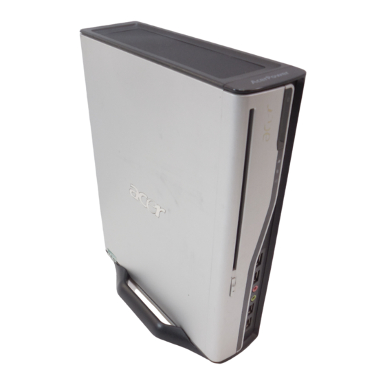
TV, DVD movies and theater-quality surround sound, the Aspire L310 has the performance to do it all — just like a big tower PC. Max versatility, mini size, the Aspire L310 is a groundbreaking product for the home PC market. -
Page 10: Features
D-sub (15 pin) for CRT and LCD monitor output from Intel 946GZ directly DVI-D translate from Intel 946GZ by Chrontel CH7307C 34mm x 34mm, 1226 ball PBGA Support dual-view on D-sub+DV, D-sub+TV TV output is an option for Aspire L310 Mini PCI/Mini Card Slot Slot Type: 3A Slot Quantity: 1... -
Page 11: System Led Definition
HDD state LED IDE active: Blue IDE idle: Off LAN state LED LAN active: Blue LAN idle: Of ODD state LED ODD active: Blue ODD idle: Off Aspire L310 Power state LED S0: Blue Steady S1/S3: Blue Blinking S4/S5: Off Chapter 1... - Page 12 1 D-sub (CRT)+ DVI port connector 1 GigaLAN port 2 USBx2 connectors 6 ports Audio jack 1 19V DC-in jack For Aspire L310 1 D-sub (CRT)+ DVI port connector 1 GigaLAN port 1 USBx2 connectors 1 1394 6-pin with 2 USB ports...
- Page 13 1 PATA IDE slot 1 SATA IDE connector 1 2*5 front audio connector (follow Intel FPIO spec.) 1 2*7 power/LED FPIO (follow Intel FPIO spec.) 2 4-pin system FAN connectors 1 2-pin north bridge FAN connector 1 2*15 pin 1394+USB connectors Chapter 1...
-
Page 14: System Block Diagram
System Block Diagram Block Diagram LGA775 Processor Socket T 800/533 FSB DDR2 CH:A RGB Output DDRII SDRAM CONN 0 VGA CONN * 1 GMCH 533/667MHZ 946GZ SDVO S-VIDEO CH7021A-TEF TV CONN * 1 DDR2 CH:B DDRII SDRAM CONN 1 CH7307B-DE DVI CONN * 1 PCI V2.3 / 33MHZ MINI PCI... -
Page 15: Main Board Layout
Main Board Layout DCIN1 19V DC power connector 18 FUSB1394 USB&1394 header DVI_VGA1 DVI&VGA port F_1394_1 1394 header LAN1 LAN port F_USB1 USB header TVSPDIF1 TV out & SPDIF F_USB2 USB header connector OBR1 One button recovery North bridge header REAR_USB1 Rear USB port SODIMM1. - Page 16 MINIPCIE Mini PCIE slot IDE1 IDE connector South bridge BIOS socket MINIDIN1 Mini DIN header BAT1 Battery header CLR_CMOS1 clear CMOS header Chapter 1...
-
Page 17: Your Acer Desktop Tour
Your Acer Desktop tour After knowing your computer features, let us show you around your new Veriton series computer. Front and back panel AcerPower 2000 Component Component Power DC-In Audio jack Audio jack Audio jack Audio-out/Line-out jack Audio jack Microphone-in jack... - Page 18 Aspire L310 Component Component Power DC-in 1394 port TV port Audio-in Audio-out 1394 port Card reader Audio jack Audio jack Audio jack TV port Audio jack S-video Audio jack TV-out Audio jack SPDIF Chapter 1...
-
Page 19: System Peripherals
System Peripherals The Aspire T630 and AcerPower F3 computer consist of the system itself, and system peripherals, like a mouse, keyboard and a set of speakers (optional). This section provides a brief description of the basic system peripherals. Mouse (PS/2 or USB, manufacturing option) The included mouse is a standard two-button wheel mouse. - Page 20 Chapter 1...
-
Page 21: Acer Empowering Technology
Acer Empowering Technology Acer’s innovative Empowering Technology makes it easy for you to access frequently used functions and manage your new Acer notebook. It features the following handy utilities: Acer eSettings Management accesses system information and adjusts settings easily. •... -
Page 22: Acer Elock Management
Interfaces - includes serial ports, parallel port, infrared (IR), and Bletooth. • To activate Acer eLock Management, a password must be set first. Once set, you can apply locks to any of the devices. Lock(s) will immediately be set without any reboot necessary, and will remain locked after rebooting, until unlocked. -
Page 23: Acer Edatasecurity Management
Acer eDataSecurity Management Acer eDataSecurity Management is handy file encryption utility that protexts your files from being accessed by unauthorized persons. It is conveniently integrated with Windows explorer as a shell extension for quick and easy data encryption/decryption and also supports on-the-fly file encryption for MSN Messager and Microsoft Outlook. - Page 24 Chapter 1...
-
Page 25: Acer Eperformance Management
• Acer eAcoustics Management Acer eAcoustics Management offers you a useful tool to balance your computing power needs with your desired level of quietness. By reducing the processor speed for tasks that require less processing, the CPU and system fans can run slower, thus reducing the amount of sound generated by tehse components. -
Page 26: Acer Erecovery Management
Use this mode for processing-intensive tasks, when you require full-speed operation. Acer eRecovery Management Acer eRecovery Management is a powerful utility that does away with the need for recovery disks provided by the manufacturer. The Acer eRecovery Management utility occupies space in a hidden partition on your system’s HDD. - Page 27 For more information, please refer to “Acer eRecovery Management” NOTE: If your computer did not come with a Recovery CD or System CD, please use Acer eRecovery Management’s “System backup to optical disk” feature to burn a backup image to CD or DVD. To...
-
Page 28: Hardware Specifications And Configurations
Hardware Specifications and Configurations System Board Major Chip Item Specification System Core Logic North bridge: Intel (R) 946Gz South bridge: Intel (R) ICH7 Super I/O Controller ITE IT8718F LAN Controller Marvell 88E8056-A2-NNC1C00 Memory Controller Built-in north bridge: Intel (R) 946Gz SATA Controller Built-in ICH7 1394 Controller... - Page 29 BIOS Hotkey List Hotkey Function Description Enter BIOS Setup Utility Press while the system is booting to enter BIOS Setup Utility. System Memory Item Specification Memory Slot Number 2 Slots Supported Memory Size per Slot 256 MB ~ 1GB Supported Maximum Memory Size Supported Memory Speed 533/667MHz Supported memory voltage...
- Page 30 Number of the connectors 8 for AcerPower 2000 6 for Aspire L310 Location Rear : 4 Front : 4 (for AcerPower 2000); 2 (for Aspire L310) USB Class Support legacy keyboard for legacy mode Wake-up Event Specifications Device Power Button...
- Page 31 Thermal Design Item Description Thermal Design Thermal solutin should cover Intel (R) 2006 FMB (65W) requirement 2 4-pin smart fan for system 1 2-pin fan for north bridge Provision for optional secondary fan Adequate venting in the front of chassis Adequate venting in the rear of chassis Memory Address Map Address...
- Page 32 I/O Address Map Hex Range Devices 000-01F DMA Controller-1 020-021 Interrupt Controller-1 040-043 System Timer 060-060 Keyboard Controller 8742 061-061 System Speaker 070-071 CMOS RAM Address and Real Time Clock 080-08F DMA Page Register 0A0-0A1 Interrupt Controller-2 0C0-0DF DMA Controller-2 0F0-0FF Math Co-Processor 170-177...
- Page 33 DRQ Assignment Map DRQx System Devices Add-On-Card Devices DRQ0 Reserved DRQ1 Reserved DRQ2 DRQ3 Reserved DRQ4 Cascade DRQ5 Reserved DRQ6 Reserved DRQ7 Reserved NOTE: N - Not be used Environmental Requirements Item Specifications Temperature Operating +5°C ~ +35°C Non-operating -20 ~ +60°C (Storage package), -10°C~+60°C (un-package) Humidity Operating 15% to 80% RH, non-condensing...
-
Page 34: Power Management Function ( Acpi Support Function)
Power Management Function ( ACPI support function) Device Standby Mode Independent power management timer for hard disk drive devices (0-15 minutes, time step=1 minute). Hard disk drive goes into Standby mode (for ATA standard interface). Disable V-sync to control the VESA DPMS monitor. Resume method: device activated (Keyboard for DOS, keyboard &... -
Page 35: Dual Channel
Dual Channel VT x800 series support the Dual Channel Technology. After operating the dual channel technology, the bandwidth of memory bus will add double up to 4GB/s. The mainboard inculdes 4 DIMM slots, and each channel has two DIMM sockets as following: Channel A : DDR1, DDR3 Channel B : DDR2 , DDR4 If you want to operate the Dual Channel Technology, please note the following explanations due to... - Page 36 Chapter 1...
-
Page 37: System Utilities
Chapter 2 System Utilities BIOS (Basic Input and Output System) includes a CMOS SETUP utility which allows user to configure required setting or to active certain system features. The CMOS SETUP saves the configuration in the CMOS SRAM of the mainboard. When the power is turned off, the battery on the mainboard supplies the necessary power to the CMOS SRAM. -
Page 38: Entering Setup
Entering Setup Once enter Award BIOS CMOS Setup Utility, the Main Menu (as figure below) will appear on the screen. Use arrow keys to select among the items and press <Enter> to accept or enter the sub-menu. Note: If you can’t find the setting you want, please press “Alt+F4” to search the advanced option hidden. -
Page 39: Product Informatoin
Product Informatoin Phoenix - AwardBIOS CMOS Setup Utility Product Information Product Name AcerPower 2000/Aspire L310 Item Help System S/N Menu Level Main Board ID F1946GZ Asset Tag Number System BIOS Version 6.00 PG SMBIOS Version System BIOS ID R01-B1 BIOS Release Date... -
Page 40: Standard Cmos Features
Standard CMOS Features Phoenix - AwardBIOS CMOS Setup Utility Standard CMOS Features Date (mm:dd:yy): Wed Aug 23 2006 Item Help Time (hh:mm:ss): 11:08:43 Menu Level SATA Channel 0 Master None SATA Channel 0 Master None SATA Channel 0 Master None SATA Channel 0 Master None Drive A... - Page 41 Parameter Description Options SATA channel 0/1 Master, Allows you to configure the hard disk drive SATA HDD Auto-Detection Press [Enter] to Slave connected to the master port of SATA channel. select this option for automatic device To enter the SATA Master or Slave setup, press detection.
- Page 42 Parameter Description Options Total Memory Base + Upper + Extended = Total Memory. Chapter 2...
-
Page 43: Advanced Bios Features
Advanced BIOS Features The following screen shows the Advanced BIOS Features: Phoenix - AwardBIOS CMOS Setup Utility Advanced BIOS Features CPU Feature [Press Enter] Item Help Hard Disk Boot Priority [Press Enter] Virus Warning [Disabled] Menu Level Quick Power On Self Test [Enable] First Boot Device [Hard Disk]... -
Page 44: Cpu Feature
Parameter Description Options Boot Up Floppy Seek When Enabled, the BIOS tests (seeks) floppy Enabled drives to determine whether they have 40 or 80 Disabled tracks. Only 360-KB floppy drives have 40 tracks; drives with 720 KB, 1.2 MB, and 1.44 MB capacity all have 80 tracks. - Page 45 Parameter Description Options C1E Function CPU new added feature. System may hang Auto when SATA port 4 is in used. C1E function can Disabled fix this problem. Enable Execute Disable Bit Can improve protection against malicious Enabled "buffer overflow" attacks when properly enabled Disabled with Windows XP SP2.
-
Page 46: Advanced Chipset Features
Advanced Chipset Features Phoenix - AwardBIOS CMOS Setup Utility Advanced Chipset Features AMT BIOS Support [Enabled] Item Help GbE LAN Enabled SOL Support Enabled Menu Level IDE-R Support Enabled ** VGA Setting ** PEG/Onchip VGA Control [Auto] On-Chip Frame Buffer Size [8MB] DVMT Mode [DVMT]... - Page 47 Parameter Description Options On-Chip Frame Buffer Size This BIOS feature controls the amount of system memory 1MB, 4MB, 8MB, that is allocated to the integrated graphics processor when 16MB, 32MB, the system boots up. Please visit http://www.rojakpot.com/ 64MB, 128MB (for showFreeBOG.aspx?lang=0&bogno=325 for more detailed UMA) settings.
-
Page 48: Integrated Peripherals
:Move Enter: Select +/-/PU/PD :Value F10:Save ESC:Exit F1:General Help F5:Previous Values F7:Default Settings For Aspire L310 Phoenix - AwardBIOS CMOS Setup Utility Integrated Peripherals USB 2.0 Support [Enabled] Item Help... - Page 49 Parameter Description Options USB 2.0 Support Enables or disables USB 2.0 support function. Onboard Audio Select Enabled to use the audio capabilities of your system. Most of the following fields do not appear when this field is Disabled. Onboard LAN function Select Enabled to use the LAN capabilities of your system.
-
Page 50: Onchip Ide Device
OnChip IDE Device Phoenix - AwardBIOS CMOS Setup Utility OnChip IDE Device IDE HDD Block Mode [Press Enter] Item Help IDE DMA transfer access [Press Enter] IDE Primary transfer access [Press Enter] Menu Level IDE Primary Master PIO [Auto] IDE Primary Slave PIO [Auto] IDE Primary Master UDMA [Auto]... - Page 51 Parameter Description Options IDE Primary/Secondary Master/Slave UDMA (Ultra DMA) is a DMA data transfer Auto UDMA protocol that utilizes ATA commands and the ATA Enabled bus to allow DMA commands to transfer data at a Disabled maximum burst rate of 33 MB/s. When you select Auto in the four IDE UDMA fields (for each of up to four IDE devices that the internal PCI IDE interface supports), the system automatically...
-
Page 52: Onboard Device
Onboard Device Phoenix - AwardBIOS CMOS Setup Utility Onboard Device USB Controller [Enabled] Item Help USB 2.0 Controller [Enabled] USB Keyboard Support [Enabled] Menu Level USB Mouse Support [Enabled] Azalia Audio [Enabled] Onboard Lan Controller [Enabled] Onboard Lan Boot ROM [Disabled] :Move Enter: Select +/-/PU/PD :Value F10:Save ESC:Exit F1:General Help F5:Previous Values F7:Default Settings... - Page 53 Parameter Description Options USB Mouse Support This BIOS feature determines if support for the Enabled USB mouse should be provided by the operating Disabled system or the BIOS. Therefore, it will only affect those who are using USB mice. If your operating system offers native support for USB mice, you should select the OS option.
-
Page 54: Super Io Device
Super IO Device Phoenix - AwardBIOS CMOS Setup Utility SuperIO Device Onboard FDC Controller [Enabled] Item Help Onboard Serial Port 1 [3F8/IRQ4] Onboard Serial Port 2 [2F8/IRQ3] Menu Level Onboard Parallel Port [378/IRQ7] Parallel Port Mode [SPP] x ECP Mode Use DMA :Move Enter: Select +/-/PU/PD :Value F10:Save ESC:Exit F1:General Help F5:Previous Values F7:Default Settings Parameter... -
Page 55: Power Management Setup
Power Management Setup The Power Management menu lets you configure your system to most effectively save energy while operating in a manner consistent with your own style of computer use. Pheonix - AwardBIOS CMOS Setup Utility Power Management Setup PCI Express PM Function [Press Enter] Item Help ACPI Function... - Page 56 Parameter Description Options Power on by Ring This item allows you to power on up the system by LAN Enabled, Disabled signals. USB KB WakeUp From This item allows you to wake up the keyboard from S3 Enabled, Disabled S3(S4) (S4) stage.
-
Page 57: Pnp/Pci Configuration
PnP/PCI Configuration Phoenix - AwardBIOS CMOS Setup Utility PnP/PCI Configurations Init Display First [PCI Slot] Item Help Menu Level PCI/VGA Palette Snoop [Disabled] ** PCI Express relative items ** Maximum Payload Size [128] :Move Enter: Select +/-/PU/PD :Value F10:Save ESC:Exit F1:General Help F5:Previous Values F7:Default Settings Parameter Description... -
Page 58: Pc Health Status
PC Health Status Phoenix - AwardBIOS Setup Utility PC Health Status Item Help Intruder Detection [Disabled] Advanced Fan Speed Control [Press Enter] Menu Level Shutdown Temperature 90 C/194 F Vcore 1.23V VDIMM 1.82V + 3.3V 3.31V + 5.0V 4.94V + 12 V 11.04V CPU Temperature SYS Temperature... -
Page 59: Frequency Control
Frequency Control Phoenix - AwardBIOS CMOS Setup Utility Frequency Control CPU Clock Ratio [16 x] Item Help Auto Detect PCI Clk [Disabled] Spread Spectrum [Enabled] Menu Level :Move Enter: Select +/-/PU/PD :Value F10:Save ESC:Exit F1:General Help F5:Previous Values F7:Default Settings Parameter Description CPU Clock Ratio... -
Page 60: Load Default Settings
Load Default Settings Selecting the field loads the factory defaults for BIOS and Chipset Features which the system automatically. detects. Phoenix - Award BIOS CMOS Setup Utility Product Information PC Health Status Standard CMOS Features Frequency Control Advanced BIOS Features Load Default Settings Advanced Chipset Features Set Supervisor Password... -
Page 61: Set Supervisor/User Password
Set Supervisor/User Password When this function is selected, the following message appears at the center of the screen to assist you in creating a password. Phoenix - Award BIOS CMOS Setup Utility Product Information PC Health Status Standard CM OS Features Frequency Control Advanced BIOS Features Load Default Settings... -
Page 62: Save & Exit Setup
Save & Exit Setup Highlight this item and press <Enter> to save the changes that you have made in the Setup Utility and exit the Setup Utility. CMOS Setup Utility - Copyright (C) 1984-2005 Award Software Product Information PC Health Status Standard CMOS Features Frequency Control Advanced BIOS Features... -
Page 63: Exit Without Saving
Exit Without Saving Highlight this item and press <Enter> to discard any changes that you have made in the Setup Utility and exit the Setup Utility. CMOS Setup Utility - Copyright (C) 1984-2005 Award Software Product Information PC Health Status Standard CMOS Features Frequency Control Advanced BIOS Features... - Page 64 Chapter 2...
-
Page 65: Machine Disassembly And Replacement
Chapter 3 Machine Disassembly and Replacement This chapter will guide you how to disassemble and Reassemble the AcerPower 2000/Aspire L310. To disassemble the computer, you need the following tools: Wrist grounding strap and conductive mat for preventing electrostatic discharge. Wire cutter. -
Page 66: General Information
General Information Before You Begin Before proceeding with the disassenbly procedure, make sure that you do the following: Turn off the power to the system and all peripherals. Unplug the AC adapter and all power and signal cables from the system. Chapter 3... -
Page 67: Acerpower 2000 Disassembly Procedure
AcerPower 2000 Disassembly Procedure This section tells you how to disassemble the system when you need to perform system service. Please also refer to the disassembly video, if available. CAUTION: Before you proceed, make sure you have turned off the system and all peripherals connected to it. Opening the System Slide the system from the plate. - Page 68 Remove the top cover from the system. Pull up the three locks as shown. Detach the front bezel from the system. Chapter 3...
-
Page 69: Removing The Odd And Hdd Module
Removing the ODD and HDD Module Remove the belt and the screw holding the ODD and the HDD module. Disconnect the HDD data cable and the ODD data cable from the main board. Chapter 3... -
Page 70: Removing Cables And Memorys
Then disconnect the HDD data (highlighted in yellow circle) cable and HDD power cable (highlighted in blue circle) from the HDD module. Removing Cables and Memorys Disconnect the HDD SATA cable (red circle), USB/audio cable on one side (yellow circle) and USB/audio cable on the other side from the main board. - Page 71 Detach the front bezel from the system. Pop out the memorys and remove them from the main board. Chapter 3...
-
Page 72: Removing The Cpu
Removing the CPU Remove the four screws fastening the CPU cooler to the main board. Detach the CPU cooler from the main board. Press the CPU socket lever (highlighted in red) and pull the lever outwards a little to release the CPU lock. Chapter 3... -
Page 73: Removing The Hdd/Odd From The Module
Carefully remove the CPU from the socket on the main board. Removing the HDD/ODD from the Module Remove the four screws holding the HDD to the HDD bracket. Chapter 3... - Page 74 Pull out the HDD from the bracket. Remove the two screws fastening the ODD to the bracket. Take out the ODD from the bracket and disconnect the ODD cable from the ODD. Chapter 3...
-
Page 75: Removing The System Fan
Removing the System Fan Remove the four screws fastening the system fan on rear panel. Disconnect the system fan cable from the main board. Then take out the system fan. Chapter 3... -
Page 76: Removing The Main Board And Usb/Audio Module
Removing the Main Board and USB/Audio Module Remove the eight screws and one screw-nut fastening the main board to the housing. Take out the main board from the housing. Remove the screw fastening the audio module to the housing. Chapter 3... - Page 77 Remove the two screws holing the audio module to the housing. Remove the audio board from the housing. Then remove the audio bracket from the housing. Chapter 3...
-
Page 78: Aspire L310 Disassembly Procedure
Aspire L310 Disassembly Procedure Opening the System Slide the system from the plate. Then place the system on a flat surface. Remove the screw fastening the top cover. Chapter 3... - Page 79 Remove the top cover from the system. Pull up the three locks as shown. Detach the front bezel from the system. Chapter 3...
-
Page 80: Removing The Odd And Hdd Module
Removing the ODD and HDD Module Remove the belt and the screw holding the ODD and the HDD module. Disconnect the HDD data cable and the ODD data cable from the main board. Chapter 3... -
Page 81: Removing Cables And Memorys
Then disconnect the HDD data (highlighted in yellow circle) cable and HDD power cable (highlighted in blue circle) from the HDD module. Removing Cables and Memorys Disconnect the HDD SATA cable (red circle), USB/audio cable on one side (yellow circle) and USB/audio cable on the other side from the main board. - Page 82 Detach the front bezel from the system. Pop out the memorys and remove them from the main board. Chapter 3...
-
Page 83: Removing The Cpu
Removing the CPU Remove the four screws fastening the CPU cooler to the main board. Detach the CPU cooler from the main board. Press the CPU socket lever (highlighted in red) and pull the lever outwards a little to release the CPU lock. Chapter 3... -
Page 84: Removing The Hdd/Odd From The Module
Carefully remove the CPU from the socket on the main board. Removing the HDD/ODD from the Module Remove the four screws holding the HDD to the HDD bracket. Chapter 3... - Page 85 Pull out the HDD from the bracket. Remove the two screws fastening the ODD to the bracket. Take out the ODD from the bracket and disconnect the ODD cable from the ODD. Chapter 3...
-
Page 86: Removing The System Fan
Removing the System Fan Remove the four screws fastening the system fan on rear panel. Disconnect the system fan cable from the main board. Then take out the system fan. Chapter 3... -
Page 87: Removing The Main Board And Usb/Audio Module
Removing the Main Board and USB/Audio Module Remove the eight screws and one screw-nut fastening the main board to the housing. Take out the main board from the housing. Remove the screw fastening the audio module to the housing. Chapter 3... - Page 88 Remove the two screws holing the audio module to the housing. Remove the audio board from the housing. Then remove the audio bracket from the housing. Chapter 3...
-
Page 89: Troubleshooting
Chapter 4 Troubleshooting This chapter provides troubleshooting information for the Veriton 7900Pro/6900Pro/5900Pro Power-On Self-Test (POST) Index of Error Message Index of Error Symptoms Undetermined Problems Chapter 4... -
Page 90: Power-On Self-Test (Post)
Power-On Self-Test (POST) Each time you turn on the system, the Power-on Self Test (POST) is initiated. Several items are tested during POST, but is for the most part transparent to the user. The Power-On Self Test (POST) is a BIOS procedure that boots the system, initializes and diagnoses the system components, and controls the operation of the power-on password option. - Page 91 Checkpoint Description Initial Superio_Early _Init switch Reserved 1. Blank out screen 2. Clear CMOS error flag Reserved 1. Clear 8042 interface 2. Initialize 8042 self-test 1. Test special keyboard controller for Winbond 977 series Super I/O chips. 2. Enable keyboard interface. Reserved 1.
- Page 92 Checkpoint Description 1. Check validity of RTC value: e.g. a value of 5Ah is an invalid value for RTC minute. 2. Load CMOS settings into BIOS stack. If CMOS checksum fails, use default value instead. 3. Prepare BIOS resource map for PCI & PnP use. If ESCD is valid, take into consideration of the ESCD’s legacy information.
- Page 93 Checkpoint Description Test 8254. Reserved Test 8259 interrupt mask bits for channel 1 Reserved Test 8259 interrupt mask bits for channel 2 Reserved Reserved Test 8259 functionality Reserved Reserved Reserved Initialize EISA slot Reserved 1. Calculate total memory by testing the last double word of each 64K. 2.
- Page 94 Checkpoint Description 1. Initialize Init_Onboard_Super_IO switch. 2. Initialize Init_Onboard_AUDIO switch. Reserved Reserved Okay to enter Setup utility; i.e. not until this POST stage can users enter the CMOS setup utility. Reserved Reserved Reserved Reserved Initialize PS/2 Mouse Reserved Prepare memory size information for function call: INT 15h ax=E820h Reserved Turn on L2 cache...
- Page 95 Checkpoint Description Reserved 1. Switch back to text mode if full screen logo is supported. -If errors occur, report errors & wait for keys -If no errors occur or F1 key is pressed to continue: Clear EPA or customization logo. Reserved Reserved 1.
-
Page 96: Post Error Messages List
POST Error Messages List If you cannot run the diagnostics program tests but did receive a POST error message, use “POST Error Messages List” to diagnose system problems. If you did not receive any error message, look for a description of your error symptoms in “Error Symptoms List”... - Page 97 BIOS Messages Action/FRU Keyboard Error Or No Keyboard Present Cannot initialize the keyboard. Make sure the keyboard is attached correctly and no keys are pressed during POST. To purposely configure the system without a keyboard, set the error halt condition in Setup to HALT ON ALL, BUT KEYBOARD.
-
Page 98: Error Symptoms List
Error Symptoms List NOTE: To diagnose a problem, first find the error symptom in the left column. If directed to a check procedure, replace the FRU indicated in the check procedure. If no check procedure is indicated, the first Action/ FRU listed in right column is the most likely cause. - Page 99 Error Symptom Action/FRU Diskette drive read/write error. 1. Diskette. 2. Diskette drive cable. 3. Diskette drive. 4. Main board. Diskette drive LED comes on for more 1. Diskette than 2 minutes when reading data. 2. Diskette drive connection/cable 3. Diskette drive 4.
- Page 100 Error Symptom Action/FRU CD/DVD-ROM drive does not read and 1. CD may have dirt or foreign material on it. Check with a there are no messages are displayed. known good disc. 2. Ensure the CD/DVD-ROM driver is installed properly. 3. CD/DVD-ROM drive. CD/DVD-ROM drive can play audio CD 1.
- Page 101 Error Symptom Action/FRU Display problem not listed above 1. “Monitor" (including blank or illegible monitor). 2. Load default settings (if screen is readable). 3. Main board Chapter 4...
- Page 102 Error Symptom Action/FRU Parallel/Serial Ports Execute “Load BIOS Default Settings” in BIOS Setup to confirm ports presence before diagnosing any parallel/serial ports problems. Serial or parallel port loop-back test 1. Make sure that the LPT# or COM# you test is the same failed.
-
Page 103: Undetermined Problems
Check all cables and connectors for proper installation. If the jumpers, switches and voltage settings are correct, remove or disconnect the following, one at a time: 10. Non-Acer devices External devices Any adapter card (modem card, LAN card or video card, if installed) - Page 104 Chapter 4...
-
Page 105: Main Board Layout
Chapter 5 Jumper and Connector Information Main Board Layout DCIN1 19V DC power connector 18 FUSB1394 USB&1394 header DVI_VGA1 DVI&VGA port F_1394_1 1394 header LAN1 LAN port F_USB1 USB header TVSPDIF1 TV out & SPDIF F_USB2 USB header connector OBR1 One button recovery North bridge header... - Page 106 USB_1394CN1 USB&1394 port CPU socket NB_FAN1 North bridge FAN header 27 SATAP5CN1 5V SATA power AUDIO1 Rear audio port SATAP12CN1 12V SATA power FAUDIO1 Front audio header Front pannel header MINIPCI1 Mini PCI slot INTR1 intruder header MINIPCIE Mini PCIE slot IDE1 IDE connector South bridge...
-
Page 107: Fru (Field Replaceable Unit) List
DIFFERENT part number code to those given in the FRU list of this printed Service Guide. You MUST use the local FRU list provided by your regional Acer office to order FRU parts for repair and service of customer machines. -
Page 108: Acerpower 2000/Aspire L310 Exploded Diagram
AcerPower 2000/Aspire L310 Exploded Diagram Chapter 6... -
Page 109: Parts
Case/ Cover/ Bracket Assembly FOOT PEDESTAL ASSY "FOOT_PEDESTAL ASSEMBLY, 42.P35VF.002 ROHS" "CHASSIS KIT W/I P161 BEZEL ,SYS FAN AND "ACER BEAGLE ACERPOWER L3 60.P41VF.001 TOP COVER" CASE,CONTAIN CHASSIS , P161 BEZEL , SYS FAN AND TOP COVER" "CHASSIS KIT W/I P162 BEZEL ,SYS FAN AND "ACER BEAGLE ACERPOWER L3... - Page 110 PARTNAME DESCRIPTION ACER PART NO. ACER_LOGO2 (POLISHED MYLAR) ACER_LOGO2 (POLISHED 47.S600F.001 MYLAR) FOOT BASE "FOOT-U-BASE, ROHS" 47.P35VF.002 DVD-RW Drive "8X SUPER MULTI (DL), SLOT, UJ-845, LF, W/I UJ-845 KU.00807.042 STANDARD BEZEL" "8X SUPER MULTI (DL), SLOT, DVR-K06RS, DVR-K06RS KU.00805.037 LF, W/I STANDARD BEZEL"...
- Page 111 PARTNAME DESCRIPTION ACER PART NO. "LOGITECH USB OPTICAL MOUSE, MUV "M-UV ACR1 (BLACK), (ROHS)" MS.MUV01.005 ACR1, (ROHS), W/ STK LABEL" "WIRELESS MOUSE, M-RAU95, ROHS M-RAU95 MS.RAF01.004 LOGITECH" Keyboard "USB KEYBOARD,KU-0355,US KU-0355(SILVER+BLACK) KB.KUS03.188 VER.,104KS,JPN ABS(WITH EKEY),LF" "USB KEYBOARD,KU-0355,IN'L US KU-0355(SILVER+BLACK) KB.KUS03.189 VER.,104KS,JPN ABS(WITH EKEY),ROHS"...
- Page 112 SP.S1006.007 EUROPE PLUG TYPE,LOGITECH LOGO (ROHS)" "LOGITECH 2.0 SPEAKER, S100, 110V WITH S100 SP.S1006.008 US PLUG TYPE, ACER LOGO (ROHS)" "LOGITECH 2.0 SPEAKER, S100, 230V W/ S100 SP.S1006.009 AUSTRALIA PLUG TYPE, ACER LOGO (ROHS)" LOGITECH 2.0 SPEAKER S100 110V W/US S100 SP.S1006.010...
- Page 113 POWER SWITCH AND POWER/HDD/ODD POWER SWITCH AND POWER/ 50.S600F.008 CABLE HDD/ODD Case/ Cover/ Bracket Assembly CHASSIS KIT H107 W/I A161 BEZEL "ACER BEAGLE L3 CASE H107, 60.S600F.003 A161" CHASSIS KIT H102 W/I A161 BEZEL ACER BEAGLE L3 CASE H102. 60.S600F.001 A161 "CHASSIS KIT W/I P161 BEZEL ,SYS FAN AND...
- Page 114 PARTNAME DESCRIPTION ACER PART NO. FRONT BEZEL ASSY W/O ANTENNA (A161) A161 W/O ANTENNA BEZEL 60.S600F.002 ASSEMBLY FRONT BEZEL ASSY (P162) "P162 BEZEL ASSEMBLY, ROHS" 60.P35VF.002 ODD/HDD BRACKET W/I BLACK HANDLE "ODD/HDD BRT,WITH BLACK 33.P410F.001 HANDLE" PLASTIC HANDLE "PLASTIC HUSKY-HANDLE, USED 42.P35VF.001...
- Page 115 PARTNAME DESCRIPTION ACER PART NO. Combo Module "CW-8124 , SLOT IN , WITH STANDARD CW-8124 KO.02406.019 BEZEL" Processor P4 651 (3.4G 2M 800FSB) D-0 HH80552PG0962M KC.DD001.651 P4 641 (3.2G 2M 800FSB) D-0 HH80552PG0882M KC.DD001.641 P4 631 (3.0G 2M 800FSB) D-0 HH80552PG0802M KC.DD001.631...
- Page 116 PARTNAME DESCRIPTION ACER PART NO. "USB KEYBOARD,KU-0355,DUTCH KU-0355(SILVER+BLACK) KB.KUS03.197 VER.,105KS,JPN ABS(WITH EKEY),ROHS" "USB KEYBOARD,KU-0355,PORTUGESE KU-0355(SILVER+BLACK) KB.KUS03.198 VER.,105KS,JPN ABS(WITH EKEY),ROHS" "USB KEYBOARD,KU-0355,SWISS KU-0355(SILVER+BLACK) KB.KUS03.199 VER.,105KS,JPN ABS(WITH EKEY),ROHS" "USB KEYBOARD,KU-0355,BELGIUM KU-0355(SILVER+BLACK) KB.KUS03.200 VER.,105KS,JPN ABS(WITH EKEY),ROHS" "USB KEYBOARD,KU-0355,HOLLAND KU-0355(SILVER+BLACK) KB.KUS03.201 VER.,105KS,JPN ABS(WITH EKEY),ROHS"...
- Page 117 PARTNAME DESCRIPTION ACER PART NO. DDRII533 256MB SO-DIMM HYMP532S64BP6-C4 KN.2560G.012 DDRII667 512MB SO-DIMM HYMP564S64BP6-Y5 KN.5120G.014 DDRII533 256MB SO-DIMM NT256T64UH4A1FN-37B KN.25603.029 DDRII533 512M SO-DIMM AS6E8E63B-5C1A AS6E8E63B-5C1A KN.5120E.002 PSC DIMM DDRII 533 512MB AL6E8E63B- AL6E8E63B-5C1A KN.5120E.004 5C1A DDRII667 256MB SO-DIMM HYMP532S64BP6-Y5 KN.2560G.013 Pointing Device "LOGITECH USB OPTICAL MOUSE, MUV...