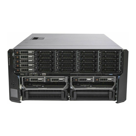
Dell PowerEdge VRTX Owner's Manual
Vrtx enclosure owner's manual
Hide thumbs
Also See for PowerEdge VRTX:
- Reference manual (931 pages) ,
- User manual (193 pages) ,
- Owner's manual (159 pages)

Related Manuals for Dell PowerEdge VRTX


Summary of Contents for Dell PowerEdge VRTX
- Page 1 Dell PowerEdge VRTX Enclosure Owner's Manual Regulatory Model: E22S Regulatory Type: E22S001...
-
Page 2: Notes, Cautions, And Warnings
CAUTION: A CAUTION indicates either potential damage to hardware or loss of data and tells you how to avoid the problem. WARNING: A WARNING indicates a potential for property damage, personal injury, or death. © 2013 Dell Inc. Trademarks used in this text: Dell , the Dell logo, Dell Boomi , Dell Precision , OptiPlex... -
Page 3: Table Of Contents
Contents Notes, Cautions, and Warnings....................2 1 About Your System........................9 ................................9 Introduction ..........................9 Terms Used In The Document ..............................10 System Overview ........................12 Front-Panel Features And Indicators ..............................14 KVM Features ..........................14 Hard-Drive Indicator Patterns ..............................15 LCD Module ........................ - Page 4 4 Installing Enclosure Components...................33 .............................. 33 Recommended Tools ............................. 33 Front Bezel (Optional) ..........................33 Installing The Front Bezel ..........................34 Removing The Front Bezel ............................34 System Feet—Tower Mode ..........................34 Removing The System Feet ..........................35 Installing The System Feet ......................35 Wheel Assembly (Optional)—Tower Mode ........................35 Installing The Wheel Assembly...
- Page 5 ..............................58 Blower Modules ..........................58 Removing A Blower Module ..........................59 Installing A Blower Module ........................60 Removing The Blower Module Bay ........................60 Installing The Blower Module Bay ................................61 I/O Module ..........................61 Removing The I/O Module ..........................62 Installing The I/O Module ............................62 Optical Drive (Optional) ..........................
- Page 6 ....................89 Removing The System Top And Base Covers ....................90 Installing The System Top And Base Covers .................................91 Mounting Ears .......................... 91 Removing The Mounting Ears ........................... 92 Installing The Mounting Ears ..........................93 Replacing The LCD Module ............................93 Control Panel Assembly ..........................
- Page 7 Troubleshooting Hard Drives ........................126 Troubleshooting Expansion Cards ........................127 Troubleshooting The I/O Module 7 System Board Connectors.....................129 8 Technical Specifications....................... 133 ............................133 Enclosure Specifications ............................ 134 I/O Module Specifications ..........................134 Environmental Specifications 9 Getting Help..........................139 ..............................139 Contacting Dell .............................139 Documentation Feedback...
-
Page 9: About Your System
About Your System Introduction This document provides information on the Dell PowerEdge VRTX enclosure. Terms Used In The Document The following table describes the terms used in this document. Term Description Enclosure or chassis Refers to the VRTX enclosure. Server module(s) Refers to Dell PowerEdge M520 or M620 server module(s) that are specifically configured for the enclosure. -
Page 10: System Overview
System Overview Your system includes up to four Dell PowerEdge M520 or M620 server modules installed in the Dell PowerEdge VRTX enclosure (chassis) that are specifically configured for the enclosure, and can be identified by a label marked PCIe on the server module. - Page 11 Figure 2. Server Module and Hard-Drive Numbering (2.5 inch Hard-Drive Chassis) 1. server module numbering 2. hard-drive numbering Figure 3. Server Module and Hard-Drive Numbering (3.5 inch Hard-Drive Chassis) 1. server module numbering...
-
Page 12: Front-Panel Features And Indicators
2. hard-drive numbering Front-Panel Features And Indicators Figure 4. Front-Panel Features And Indicators—2.5 Inch Hard Drive Chassis... - Page 13 Figure 5. Front-Panel Features And Indicators—3.5 Inch Hard Drive Chassis Item Indicator, Button, or Icon Description Connector USB connectors (2) Allows a keyboard and mouse to be connected to the system. LCD panel Provides system information and status and error messages to indicate when the system is operating correctly or when the system needs attention.
-
Page 14: Kvm Features
Item Indicator, Button, or Icon Description Connector 3.5 inch hard Up to twelve 3.5 inch hot- drive enclosure swappable hard drives. Information tag A slide-out label panel which allows you to record system information such as Service Tag, NIC, MAC address, the system's electrical rating, and Worldwide Regulatory Agency marks. -
Page 15: Lcd Module
2. hard-drive status indicator (green and amber) Drive-Status Condition Indicator Pattern Blinks green two Identifying drive or preparing for removal times per second Drive ready for insertion or removal NOTE: The drive status indicator remains off until all hard drives are initialized after the system is turned on. - Page 16 • A deployment setup that allows you to configure the CMC’s network settings during initial system setup. • Menus to configure the iDRAC in each server module. • Status information screens for each server module. • Status information screens for the modules installed in the back of the enclosure, including the I/O module, blower modules, CMC, KVM, and power supplies.
- Page 17 DVD Mapping From this screen, you can view the DVD to server mapping information, map another server to the DVD drive on the chassis, or unmap the existing connection. KVM Mapping Menu From this screen, you can view the KVM to server mapping information, map another server to the KVM, or unmap the existing connection.
-
Page 18: Back-Panel Features And Indicators
Back-Panel Features And Indicators Figure 8. Back-Panel Features and Indicators Item Indicator, Button, or Icon Description Connector PCIe expansion card slots Allows you to connect up to five low-profile PCI Express low-profile (5) expansion cards. PCIe expansion card slots Allows you to connect up to three full-height PCI Express full height (3) expansion cards. -
Page 19: Power Supply Indicators
Item Indicator, Button, or Icon Description Connector Power supply (PSU3) 1100 W AC Power supply (PSU1) 1100 W AC Power supply (PSU2) 1100 W AC Power Supply Indicators Each AC power supply has an illuminated translucent handle that serves as an indicator to show whether power is present or whether a power fault has occurred. -
Page 20: Blower Module Indicators
Blower Module Indicators Figure 10. Blower Module Indicators 1. blower module fault indicator 2. blower module power indicator The indicators provide the following information: Indicator Description Blower module Steady Green The blower module is receiving power. power indicator The blower module is not receiving power. Blower module fault Blinking Amber The blower module is in a fault condition. -
Page 21: I/O Module Indicators
Blinking Blue The CMC is identifying the I/O module. Blinking Amber The I/O module is in a fault condition. The I/O module is powered off, or booting is in progress. For more information, see the I/O module's documentation at dell.com/poweredgemanuals. -
Page 22: Cmc Indicators
CMC Indicators Figure 12. CMC Indicators 1. status/identification indicator (CMC 1) 2. power indicator (CMC 1) 3. power indicator (CMC 2) 4. status/identification indicator (CMC 2) The CMC indicators on the back panel of the enclosure provide the following information: Indicator Description Power indicator... -
Page 23: Cmc Fail-Safe Mode
Dell Chassis Management event. For more information on updating the CMC firmware, see the Controller for Dell PowerEdge VRTX User’s Guide at dell.com/esmmanuals. CMC error detection Chassis management resumes after the CMC resets or chassis fails over to the standby CMC. -
Page 24: Configuration Wizard
The CMC is preset for Dynamic Host Configuration Protocol (DHCP). To use a static IP address, you must toggle the CMC setting from DHCP to a static address by either running the LCD configuration wizard, or by using a management station Dell Chassis Management Controller for Dell PowerEdge VRTX User’s and CLI commands. For more information, see the Guide at dell.com/esmmanuals. -
Page 25: Other Information You May Need
Dell systems management application documentation provides information about installing and using the systems management software. • For the full name of an abbreviation or acronym used in this document, see the Glossary at dell.com/support/ manuals. • Any media that ships with your system that provides documentation and tools for configuring and managing your system, including those pertaining to the operating system, system management software, system updates, and system components that you purchased with your system. -
Page 27: Initial System Configuration
• Your system supports Dell PowerEdge M520 and M620 server modules that are specifically configured for the enclosure, and can be identified by a label marked PCIe on the server module. If you install PowerEdge M520 and M620 server modules that are not configured for the enclosure, an error message is displayed. -
Page 28: Logging In To The Cmc
NOTE: For a detailed description on configuring the CMC settings, see the Dell Chassis Management Controller for Dell PowerEdge VRTX User’s Guide at dell.com/esmmanuals. Connect to the CMC IP address through the Web browser using the default logon credentials. The default user name is root and password is calvin. -
Page 29: Configuring Enclosure Components
Each server module installed in the VRTX enclosure supports two PCIe mezzanine cards in Fabric B and Fabric C slots. To locate the Fabric B and Fabric C slots, see the server module's Owner's Manual at dell.com/ poweredgemanuals. The PCIe mezzanine cards are mapped to the PCIe expansion slots on the enclosure. For... -
Page 30: Supported I/O Modules
Dell PowerEdge VRTX 1Gb R1-PT pass-through module • Dell PowerEdge VRTX 1Gb R1-2401 switch module NOTE: For more information on the I/O modules, see the I/O module's documentation at dell.com/ poweredgemanuals. Configuring Network Settings For The I/O Module You can specify the network settings for the interface used to manage the I/O module. -
Page 31: Managing Pcie Slots
Dell Chassis Management For more information on managing the PCIe slots using the CMC web interface, see the Controller for Dell PowerEdge VRTX User’s Guide at dell.com/esmmanuals. Managing Chassis Storage The enclosure provides shared storage with single Shared PERC/Expander configurations. The Shared PERC card supports Single Root Input Output Virtualization (SR-IOV) feature and enables the server modules map to the local storage through the PCIe switches on the enclosure's system board. - Page 32 NOTE: For information on setting up storage controllers, physical disks, and virtual disks, see the Dell Chassis Management Controller for PowerEdge VRTX User’s Guide at dell.com/esmmanuals.
-
Page 33: Installing Enclosure Components
Installing Enclosure Components WARNING: Whenever you need to lift the system, get others to assist you. To avoid injury, do not attempt to lift the system by yourself. WARNING: Exercise care when removing or installing components when the system is on, to avoid the risk of electric shock. -
Page 34: Removing The Front Bezel
Figure 14. Removing and Installing the Front Bezel 1. release tab 2. keylock 3. front bezel 4. bezel tabs Removing The Front Bezel Insert the bezel key in the keylock. Keeping the keylock pressed with the bezel key, rotate the keylock to the unlocked position. Press the release tab at the top of the bezel toward the right. -
Page 35: Installing The System Feet
Figure 15. Removing and Installing the System Feet 1. system feet (4) 2. screws (4) 3. screw holes (4) 4. system base cover Installing The System Feet Align the screw holes on the system feet with the screw holes on the system base cover. Install the screws to secure the system feet to the system base cover. - Page 36 NOTE: The front and back wheel plates are labeled. To reduce the chassis weight, remove the following (if required): a) Front bezel (if installed) b) Hard drives. See Removing A Hot-Swap Hard Drive. c) Server modules. See Removing A Server Module.
- Page 37 Figure 16. Removing and Installing the Wheel Assembly 1. hooks for the metal stands (4) 5. screws (2) 2. metal stands (2) 6. tabs on system base cover (4) 3. back wheel plate 4. front wheel plate...
-
Page 38: Removing The Wheel Assembly
Figure 17. Removing and Installing the Power Cable Retention Bracket 1. chassis slots 2. tabs on the power cable retention bracket (2) 3. power cable retention bracket Removing The Wheel Assembly Remove any cables routed through the power cable retention bracket. Slide the power cable retention bracket to the right to unlock it. -
Page 39: Opening And Closing The System
Damage due to servicing that is not authorized by Dell is not covered by your warranty. Read and follow the safety instructions that came with the product. -
Page 40: Closing The System
Damage due to servicing that is not authorized by Dell is not covered by your warranty. Read and follow the safety instructions that came with the product. -
Page 41: Hard Drives
NOTE: Components that are hot-swappable are marked orange and touch points on the components are marked blue. Figure 19. Inside the System 1. cooling fans (6) 9. system base cover 2. cooling shroud 10. hard drives (25) 3. CMC card indicators (2) 11. -
Page 42: Removing A 2.5 Inch Hard-Drive Blank
NOTE: The following procedures apply to the hard drives in the enclosure. For server module-specific hard drives, see the server module's Owner's Manual at dell.com/poweredgemanuals. Removing A 2.5 Inch Hard-Drive Blank CAUTION: To maintain proper system cooling, all empty hard-drive slots must have hard-drive blanks installed. -
Page 43: Installing A 3.5 Inch Hard-Drive Blank
Figure 21. Removing and Installing a 3.5 Inch Hard-Drive Blank 1. hard-drive blank 2. release button Installing A 3.5 Inch Hard-Drive Blank If installed, remove the front bezel. Insert the hard-drive blank into the hard-drive slot until the release button clicks into place. If applicable, install the front bezel. -
Page 44: Installing A Hot-Swap Hard Drive
Damage due to servicing that is not authorized by Dell is not covered by your warranty. Read and follow the safety instructions that came with the product. -
Page 45: Removing A Hard Drive From A Hard-Drive Carrier
Removing A Hard Drive From A Hard-Drive Carrier Remove the screws from the slide rails on the hard-drive carrier. For the 2.5 inch hard drive, turn the hard-drive carrier upside down, and remove the screws from the side rails on the hard-drive carrier. -
Page 46: Installing A Hard Drive Into A Hard-Drive Carrier
Damage due to servicing that is not authorized by Dell is not covered by your warranty. Read and follow the safety instructions that came with the product. -
Page 47: Removing A Server Module
Removing A Server Module If installed, remove the front bezel. Turn off the server module using the operating system commands or the CMC. When a server module is powered off, its front-panel power indicator is off. Press the release button on the server module handle. Pull out the server module handle to unlock the server module from the enclosure. -
Page 48: Configuring A Server Module
Remove any mezzanine cards installed in Fabric B and Fabric C slots of the server module. Install PCIe Mezzanine cards in the vacant Fabric B and Fabric C slots. For more information on installing the PCIe Mezzanine cards, see the server module's Owner's Manual at dell.com/ poweredgemanuals. -
Page 49: Installing A Server Module
Installing A Server Module Your system supports Dell PowerEdge M520 and M620 server modules that are specifically configured for the VRTX enclosure, and can be identified by a label marked PCIe on the top of the server module. If you are installing a new server module, remove the plastic cover from the I/O connector(s) and save for future use. -
Page 50: Removing A Power Supply
Damage due to servicing that is not authorized by Dell is not covered by your warranty. Read and follow the safety instructions that came with the product. - Page 51 Figure 28. Removing and Installing a Power Supply 1. connector 2. power supply 3. power supply handle 4. release latch Figure 29. Securing the Power Cable (Without Wheel Assembly)
-
Page 52: Installing A Power Supply
Damage due to servicing that is not authorized by Dell is not covered by your warranty. Read and follow the safety instructions that came with the product. -
Page 53: Cooling Shroud
Damage due to servicing that is not authorized by Dell is not covered by your warranty. Read and follow the safety instructions that came with the product. -
Page 54: Installing The Cooling Shroud
Damage due to servicing that is not authorized by Dell is not covered by your warranty. Read and follow the safety instructions that came with the product. -
Page 55: Cooling Fans
Damage due to servicing that is not authorized by Dell is not covered by your warranty. Read and follow the safety instructions that came with the product. -
Page 56: Installing A Cooling Fan
Damage due to servicing that is not authorized by Dell is not covered by your warranty. Read and follow the safety instructions that came with the product. - Page 57 To reduce the chassis weight, remove the following (if required): a) hard drives b) server modules c) power supplies If applicable, rotate the system feet inward and lay the system on its side on a flat stable surface, with the cover release latch side on top.
-
Page 58: Installing The Cooling-Fan Assembly
Damage due to servicing that is not authorized by Dell is not covered by your warranty. Read and follow the safety instructions that came with the product. -
Page 59: Installing A Blower Module
Damage due to servicing that is not authorized by Dell is not covered by your warranty. Read and follow the safety instructions that came with the product. -
Page 60: Removing The Blower Module Bay
Damage due to servicing that is not authorized by Dell is not covered by your warranty. Read and follow the safety instructions that came with the product. -
Page 61: I/O Module
Damage due to servicing that is not authorized by Dell is not covered by your warranty. Read and follow the safety instructions that came with the product. -
Page 62: Installing The I/O Module
Damage due to servicing that is not authorized by Dell is not covered by your warranty. Read and follow the safety instructions that came with the product. - Page 63 10. Disconnect the power/data cable from the system board. 11. Disconnect the power/data cable from the back of the optical drive. Note the routing of the power/data cable as you remove them from the system board and the optical drive. You must route these cables properly when you replace them to prevent them from being pinched or crimped.
-
Page 64: Installing The Optical Drive
Damage due to servicing that is not authorized by Dell is not covered by your warranty. Read and follow the safety instructions that came with the product. -
Page 65: Cmc Card Indicators
CMC Card Indicators Figure 38. CMC Card Indicators 1. status indicator 2. power indicator The CMC card indicators provide the following information: Indicator Description Power indicator Green The CMC card is receiving power. The CMC card is not receiving power. Status indicator Blue The CMC card is active and operating normally. -
Page 66: Removing A Cmc Card
Damage due to servicing that is not authorized by Dell is not covered by your warranty. Read and follow the safety instructions that came with the product. -
Page 67: Installing A Cmc Card
Damage due to servicing that is not authorized by Dell is not covered by your warranty. Read and follow the safety instructions that came with the product. -
Page 68: Installing The Pcie Cage Door
Damage due to servicing that is not authorized by Dell is not covered by your warranty. Read and follow the safety instructions that came with the product. - Page 69 NOTE: If the system is in the rack mode, the rack door may prevent the removal and installation of the PCIe cage. If installed, remove the front bezel. Turn off the server modules using the operating system commands or the CMC. Turn off the enclosure, including any attached peripherals, and disconnect the enclosure from the electrical outlet.
- Page 70 Figure 41. Removing and Installing the PCIe Cage 1. metal standoffs (2) 6. expansion-card riser connectors (2) 2. screws (2) 7. metal tabs on the chassis (4) 3. release latch 8. screw holes (2) 4. PCIe cage 9. bracket on chassis side 5.
-
Page 71: Installing The Pcie Cage
Damage due to servicing that is not authorized by Dell is not covered by your warranty. Read and follow the safety instructions that came with the product. -
Page 72: Expansion Card Operational Power Status
Location PCIe Slot Fabric Height Length Link Width System board Low Profile Half Length The following table provides guidelines for installing expansion cards to ensure proper cooling and mechanical fit. The expansion cards with the highest priority must be installed first using the slot priority indicated. All other expansion cards must be installed in card priority and slot priority order. -
Page 73: Pcie Slot Indicators
• the expansion card is replaced in the PCIe slot • the system cover is removed Chassis Status Server Module Status Expansion Card Status NOTE: The system cover must be installed for the new expansion card to power on. NOTE: To verify if a PCIe slot is powered on, see PCIe Slot Indicators. -
Page 74: Removing A Low Profile Expansion Card
Damage due to servicing that is not authorized by Dell is not covered by your warranty. Read and follow the safety instructions that came with the product. -
Page 75: Installing A Low Profile Expansion Card
Damage due to servicing that is not authorized by Dell is not covered by your warranty. Read and follow the safety instructions that came with the product. -
Page 76: Removing The Low Profile Expansion Card Divider Unit
Damage due to servicing that is not authorized by Dell is not covered by your warranty. Read and follow the safety instructions that came with the product. -
Page 77: Installing The Low Profile Expansion Card Divider Unit
Damage due to servicing that is not authorized by Dell is not covered by your warranty. Read and follow the safety instructions that came with the product. -
Page 78: Removing A Full Height Expansion Card
Damage due to servicing that is not authorized by Dell is not covered by your warranty. Read and follow the safety instructions that came with the product. -
Page 79: Installing A Full Height Expansion Card
Damage due to servicing that is not authorized by Dell is not covered by your warranty. Read and follow the safety instructions that came with the product. -
Page 80: Removing The Full-Height Expansion-Card Divider Unit
Damage due to servicing that is not authorized by Dell is not covered by your warranty. Read and follow the safety instructions that came with the product. -
Page 81: Installing The Full Height Expansion Card Divider Unit
Damage due to servicing that is not authorized by Dell is not covered by your warranty. Read and follow the safety instructions that came with the product. -
Page 82: Removing The Expansion Card Riser
Damage due to servicing that is not authorized by Dell is not covered by your warranty. Read and follow the safety instructions that came with the product. -
Page 83: Installing The Expansion Card Riser
Damage due to servicing that is not authorized by Dell is not covered by your warranty. Read and follow the safety instructions that came with the product. -
Page 84: Storage Controller Operational Power Status
The storage controller supports SAS hard drives and also enables you to set up the hard drives in RAID configurations as supported by the version of the controller included with your system. Storage Controller Operational Power Status The following table provides information on the operational power status of the integrated storage controller card when: •... -
Page 85: Storage Controller Indicators
Storage Controller Indicators Figure 50. Storage Controller Indicators 1. power indicator on system board 2. attention indicator on system board 3. power indicator on storage controller card The storage controller indicators provide the following information: Indicator Description Power indicator on Steady Green The storage controller slot is receiving power. -
Page 86: Removing An Integrated Storage Controller Card
Damage due to servicing that is not authorized by Dell is not covered by your warranty. Read and follow the safety instructions that came with the product. -
Page 87: Installing An Integrated Storage Controller Card
Damage due to servicing that is not authorized by Dell is not covered by your warranty. Read and follow the safety instructions that came with the product. -
Page 88: System Battery
Damage due to servicing that is not authorized by Dell is not covered by your warranty. Read and follow the safety instructions that came with the product. -
Page 89: System Top And Base Covers
Damage due to servicing that is not authorized by Dell is not covered by your warranty. Read and follow the safety instructions that came with the product. -
Page 90: Installing The System Top And Base Covers
Damage due to servicing that is not authorized by Dell is not covered by your warranty. Read and follow the safety instructions that came with the product. -
Page 91: Mounting Ears
Damage due to servicing that is not authorized by Dell is not covered by your warranty. Read and follow the safety instructions that came with the product. -
Page 92: Installing The Mounting Ears
Damage due to servicing that is not authorized by Dell is not covered by your warranty. Read and follow the safety instructions that came with the product. -
Page 93: Replacing The Lcd Module
Damage due to servicing that is not authorized by Dell is not covered by your warranty. Read and follow the safety instructions that came with the product. -
Page 94: Installing The Control Panel
Damage due to servicing that is not authorized by Dell is not covered by your warranty. Read and follow the safety instructions that came with the product. -
Page 95: Removing The Control Panel Board
Damage due to servicing that is not authorized by Dell is not covered by your warranty. Read and follow the safety instructions that came with the product. -
Page 96: Installing The Control Panel Board
Damage due to servicing that is not authorized by Dell is not covered by your warranty. Read and follow the safety instructions that came with the product. -
Page 97: Backplane Expander Boards
Damage due to servicing that is not authorized by Dell is not covered by your warranty. Read and follow the safety instructions that came with the product. -
Page 98: Installing A Backplane Expander Board
Damage due to servicing that is not authorized by Dell is not covered by your warranty. Read and follow the safety instructions that came with the product. -
Page 99: Hard-Drive Backplane
Damage due to servicing that is not authorized by Dell is not covered by your warranty. Read and follow the safety instructions that came with the product. - Page 100 Figure 58. Removing and Installing the 2.5 inch (x25) Hard-drive Backplane 1. hard-drive connectors (25) 5. backplane expander board 2. release pins (2) 6. hard-drive backplane 3. SAS cables on backplane expander board (2) 4. power cables (2) Figure 59. Back View of the 2.5 inch (x25) Hard-drive Backplane 1.
- Page 101 Figure 60. Removing and Installing the 3.5 inch (x12) Hard-drive Backplane 1. hard-drive connectors (12) 5. backplane expander board 2. release pins (2) 6. hard-drive backplane 3. SAS cables on backplane expander board (2) 4. power cables (2) Figure 61. Back View of the 3.5 inch (x12) Hard-drive Backplane 1.
-
Page 102: Installing The Hard-Drive Backplane
Damage due to servicing that is not authorized by Dell is not covered by your warranty. Read and follow the safety instructions that came with the product. - Page 103 10. Remove the three screws securing the PDB to the PDB bracket and remove the PDB from the bracket. Figure 62. Removing and Installing the Power Distribution Board 1. PDB bracket 5. screw hole for PDB bracket on the power supply cage 2.
-
Page 104: Installing The Power Distribution Board
Damage due to servicing that is not authorized by Dell is not covered by your warranty. Read and follow the safety instructions that came with the product. - Page 105 a) hard drives b) power supplies c) server modules If applicable, rotate the system feet inward and lay the system on its side on a flat stable surface, with the cover release latch side on top. Open the system. Remove the following: a) cooling shroud b) cooling-fan assembly c) backplane expander board...
- Page 106 Figure 64. Removing and Installing the System Board 1. system board 5. midplane planar connectors (3) 2. system board handle 6. securing pins (2) 3. spring-loaded screw 7. system-board holder 4. guide pin...
-
Page 107: Installing The System Board
Damage due to servicing that is not authorized by Dell is not covered by your warranty. Read and follow the safety instructions that came with the product. -
Page 108: Removing The Power Pass-Through Board
Damage due to servicing that is not authorized by Dell is not covered by your warranty. Read and follow the safety instructions that came with the product. -
Page 109: Installing The Power Pass-Through Board
Damage due to servicing that is not authorized by Dell is not covered by your warranty. Read and follow the safety instructions that came with the product. -
Page 110: Midplane
Damage due to servicing that is not authorized by Dell is not covered by your warranty. Read and follow the safety instructions that came with the product. - Page 111 g) system board h) power pass-through board blower module bay Holding the midplane by its slots, disengage the midplane from the two securing pins on the chassis. Rotate the midplane out and away from the system. Figure 66. Removing and Installing the Midplane 1.
-
Page 112: Installing The Midplane
Damage due to servicing that is not authorized by Dell is not covered by your warranty. Read and follow the safety instructions that came with the product. - Page 113 e) server modules Reconnect the enclosure to its electrical outlet and turn the enclosure on, including any attached peripherals. Turn on the server modules using the operating system commands or the CMC. 10. If applicable, install the front bezel.
-
Page 115: Converting The System From Tower Mode To Rack Mode
Damage due to servicing that is not authorized by Dell is not covered by your warranty. Read and follow the safety instructions that came with the product. - Page 116 a) server modules b) hard drives c) power supplies CAUTION: The blower closeout door is spring loaded. To prevent injury, exercise care when placing your hand or fingers inside the blower module bay. d) blower modules e) blower module bay To remove the system side cover: a) Press the release button on the inside of the chassis wall, to disengage the side cover from the chassis.
- Page 117 11. To remove the PCIe cage door cover: a) Remove the two screws securing the PCIe cage door cover to the cage door. b) Slide the cage door cover out of the cage door. Figure 70. Removing and Installing the PCIe Cage Door Cover 1.
- Page 118 Figure 71. Converting the Top Mounting Ear to Left Rack Ear 1. ear cover 2. cartridge 3. screws (2) 4. tabs on cartridge (3) 14. To convert the bottom mounting ear to rack right ear: a) Remove the screws securing the ear cover to be replaced by the cartridge, and remove the cover. b) Align the tabs on the cartridge with the slots in the ear, and lower the cartridge until firmly seated.
-
Page 119: Installing The Enclosure In A Rack
Figure 72. Converting the Bottom Mounting Ear to Right Rack Ear 1. mounting ear 2. cartridge 3. screws (2) 4. tabs on cartridge (2) The mounting ears are converted to rack ears. 15. Attach the rack ears to the chassis. See Installing The Mounting Ears. -
Page 121: Troubleshooting Your System
Damage due to servicing that is not authorized by Dell is not covered by your warranty. Read and follow the safety instructions that came with the product. -
Page 122: Troubleshooting Enclosure Components
Damage due to servicing that is not authorized by Dell is not covered by your warranty. Read and follow the safety instructions that came with the product. -
Page 123: Troubleshooting Power Supplies
Damage due to servicing that is not authorized by Dell is not covered by your warranty. Read and follow the safety instructions that came with the product. -
Page 124: Troubleshooting Cooling Problems
Damage due to servicing that is not authorized by Dell is not covered by your warranty. Read and follow the safety instructions that came with the product. -
Page 125: Troubleshooting A Storage Controller
Damage due to servicing that is not authorized by Dell is not covered by your warranty. Read and follow the safety instructions that came with the product. -
Page 126: Troubleshooting Expansion Cards
Damage due to servicing that is not authorized by Dell is not covered by your warranty. Read and follow the safety instructions that came with the product. -
Page 127: Troubleshooting The I/O Module
Troubleshooting The I/O Module NOTE: To eliminate the possibility of a hardware problem with the module or its attaching devices, first ensure that the module is properly initialized and configured. Check that the pass-through module or switch ports are cabled correctly. Ensure that the network daughter cards/LOM cards on the server modules are mapped to the I/O module. -
Page 129: System Board Connectors
System Board Connectors Figure 73. System Board Connectors Table 3. System Board Connectors Item Connector Description Chassis intrusion switch J_CMC1_RJ45 Ethernet port J_CMC2_RJ45 Ethernet port P_FH_RISER1 Expansion-card riser connector P_SLOT4_G2_X8_HP Low profile expansion card connector P_SLOT5_G2_X8_HP Low profile expansion card connector P_SLOT6_G2_X8_HP Low profile expansion card connector P_SLOT7_G2_X8_HP... - Page 130 Item Connector Description P_PSU_CONN PDB connector INT_STORAGE_1 Integrated storage controller card connector INT_STORAGE_2 Integrated storage controller card connector FAN 5 Cooling fan connector FAN 6 Cooling fan connector J_SAS_1A SAS connector J_SAS_1B SAS connector J_SAS_2A SAS connector J_SAS_2B SAS connector J_BP_PWR Hard-drive backplane power connector FAN 4...
- Page 131 Figure 74. System Board Connectors (Back) 1. midplane planar connectors (3)
-
Page 133: Technical Specifications
Server modules Model Up to four PowerEdge M520 and M620 server modules. NOTE: For more information on the technical specifications for the server modules, see the server module's Owner's Manual at dell.com/ poweredgemanuals. Expansion Bus Bus type PCI Express Generation 2... -
Page 134: I/O Module Specifications
Four cursor control keys, one select key, LCD screen I/O Module Specifications NOTE: For more information on the technical specifications for the I/O modules, see the module's documentation at dell.com/poweredgemanuals. Environmental Specifications Environmental NOTE: For additional information about environmental measurements for specific system configurations, see dell.com/environmental_datasheets. - Page 135 Environmental Temperature Ranges (for altitude less than 950 m or 10 °C to 35 °C (50 °F to 95 °F) with no direct sunlight on 3117 ft) the equipment. Humidity Percentage Range 10% to 80% Relative Humidity with 26 °C (78.8 °F) maximum dew point.
- Page 136 Environmental NOTE: Applies to data center environments only. Air filtration requirements do not apply to IT equipment designed to be used outside a data center, in environments such as an office or factory floor. Conductive Dust Air must be free of conductive dust, zinc whiskers, or other conductive particles.
- Page 137 Non Dell qualified peripheral cards and/or peripheral cards greater than 25 W are not supported. NOTE: For more information on the server module- specific restrictions for the expanded operating temperature range, see the technical specifications in the server module's Owner's Manual at dell.com/ poweredgemanuals.
-
Page 139: Getting Help
NOTE: If you have purchased a Dell system, you may be asked for the Service Tag. Documentation Feedback If you have feedback for this document, write to documentation_feedback@dell.com. Alternatively, you can click on the Feedback link in any of the Dell documentation pages, fill up the form, and click Submit to send your feedback.