Table of Contents
Advertisement
Available languages
Available languages
Operator's Manual
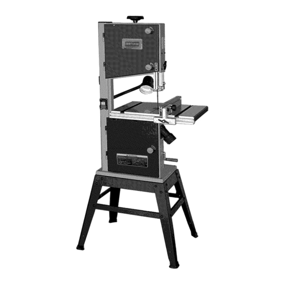
CRRFTSMAN°
1 2"
BAND SAW
Model No.
351.224000
CAUTION:
Read and follow
all Safety Rules and Operating
Instructions
before First Use
of this Product.
Customer
Helpline
1-800-266-9079
Please
have your Model No.
and Serial No. available.
Sears, Roebuck and Co., Hoffman
Estates, IL 60179 U.S.A.
www.sears.com/craftsman
29588.00 Draft (12/08)
Advertisement
Table of Contents

Related Manuals for Craftsman 351.224000


Summary of Contents for Craftsman 351.224000
- Page 1 Helpline CAUTION: Read and follow 1-800-266-9079 all Safety Rules and Operating Instructions before First Use Please have your Model No. of this Product. and Serial No. available. Sears, Roebuck and Co., Hoffman Estates, IL 60179 U.S.A. www.sears.com/craftsman 29588.00 Draft (12/08)
- Page 2 TOOL Do not use power tools in damp or wet locations. Do not expose power tools to rain. If this Craftsman tool fails due to a defect in material or • Work area should be properly lighted. workmanship within one year from the date of purchase, CALL 1-800-4-MY-HOME®...
- Page 3 • Do not force tool. It will work most efficiently at the M8 (1), Wing nut M6 (1), Tube (1), Washer M6 (1), rate for which it was designed. socket head bolt M6x45 (1), Tool holder (1), Pan head screw M5xl 0 (2), M3 Hex '1" wrench (1), M4 Hex '1" •...
- Page 4 Locate four hex bolts and four lock washers from the • Fasten the front and side beams on the paired legs with hex carriage bolts, washers and hex nuts. bag of loose parts. Mount the table to the upper table trunnion and install a bolt with washer in each hole, and •...
- Page 5 ASSEMBLE AND INSTALL RIP FENCE • Loosen the screw securing the indicator and reset if necessary to give zero degree reading. Refer to Figures 9 and 10. (See Figure 6) • To assemble the rip fence, take the fence carrier (A) and attach it to the guide rail (B) using the M8x50 carriage bolt (C) and the wing nut (D).
- Page 6 MOUNT BAND SAW TO STAND • To ensure sufficient upright stability of the machine it should be bolted to the stand (See the previous instruction how to place the machine on to the stand). For this purpose 6mm mounting holes are provided in the machine's base (see Figure 12).
- Page 7 ELECTRICAL CONNECTIONS receptacle installed in accordance with National Electric Code and local codes and ordinances. WARNING: Make sure unit is off and disconnected WARNING: This work should be performed by a quali- from power source any time wiring is inspected. fied electrician.
- Page 8 Always turn off the machine if the material is to be backed out of an uncompleted cut. • Make sure that the blade tension and blade tracking The Craftsman 12" Band Saw features welded steel are properly adjusted. frame construction and a solid cast iron table surface to •...
- Page 9 • Close the upper and lower doors by turning the door locking knobs before reconnecting the power supply. TRACKING THE SAW BLADE Blade Tension Knob Refer to Figure 22. Set the tracking of the saw blade before setting the blade guides. Once the saw blade is installed and tensioned, track the Tension Indicator saw blade by adjusting the tracking knob by hand (see...
- Page 10 Set both roller guides to within 1_2"of the saw blade side of the saw blade. Do not set the roller guides by releasing the guide adjusting screw (Figure 24) on too close as this will adversely affect the life of the saw blade.
- Page 11 The fence should be aligned with the table slots along Before changing the speed always make sure the its length (see Figure 29). machine has been unplugged from the electrical supply. For the high speed 3000 ft/min, the belt should be fitted to the rear pulley on both the motor and bandwheel (see Figure 32).
- Page 12 • The type of material being cut determines number of teeth which should be in contact with work • For soft materials, the proper blade has between 6 Refer to Figure 34, page 14 to 8 teeth per inch Steps required to keep the saw in optimum operating •...
- Page 13 SYM PTO M CORRECTIVE ACTION POSSIBLE CAUSE(S) The machine does not 1. No power supply. 1. Check the cable for breakage. work when switched 2. Defective switch. 2. Replace the lock switch. 3. Defective motor. 3. Replace the motor. The saw blade does 1.
- Page 14 Model 351.224000 Figure 34 - Replacement Parts Illustration for Band Saw ..,.L ..i_...
- Page 15 PART PART PART DESCRIPTION DESCRIPTION DESCRIPTION 29438.00 STD851008 Washer STD852006 Lock Washer Door Locking Knob Cap STD833040 Hex Bolt M6x40* 29464.00 Tension Bracket STD840610 Hex Nut M6* 29439.00 29465.00 29483.00 Door Locking Knob Body Flange Nut M8 Spring Washer STD840610 Hex Nut M6* 29466.00 Blade Tensioner...
- Page 16 PART PART PART DESCRIPTION DESCRIPTION DESCRIPTION STD315231 STD863405 Pan Head Screw M4x5* 29549.00 6203zz Bearing* Rip Fence Carrier 03838.00 29530.00 STD851008 Washer Retaining Ring 40 Micro-adjusting Knob Bracket, rear 29507.00 Tire 29531.00 29350.00 Knob Bearing Mount Cylinder w/Thread 29508.00 Lower Wheel 29532.00 Crank Handle STD863406...
- Page 17 PART PART PART DESCRIPTION DESCRIPTION DESCRIPTION STD843610 Lock Nut M6* STD840610 Hex Nut M6* 29584.00 Flange Nut M8 STD852006 29578.00 29585.00 Hex Socket Set Screw M6xl0 Spring Washer Door Locking Knob Body 29569.00 STD833040 Hex Bolt M6x40* 29586.00 Lower Table Trunion Tongue Lock 29570.00 29579.00...
- Page 18 Model 351.224000 Figure 2 - Replacement Parts Illustration for Stand PART NO. DESCRIPTION QTY. 29591.00 Front beam 29592.00 Side beam 29593.00 Legs 29594.00 Side panel 29595.00 Front panel STD541025 Rex nut ¼"* STD851006 Washer M6* STD532515 Hex carriage bolt ¼-20 x 1 _"* STD541031 Rex nut _6"* STD851008...
- Page 19 NOTES...
- Page 20 GARANTIA COMPLETA DE UN ANO PARA PREPARE EL AREA DE TRABAJO PARA LA TAREA HERRAMIENTA CRAFTSMAN A REALIZAR Si esta herramienta Craftsman fallara por causa de defectos • Mantenga el _.rea de trabajo limpia.
- Page 21 • Retire las herramientas de ajuste. Desarrolle el hgtbito de verificar que hayan sido retiradas las herramientas de ajuste antes de encender la m_.quina. Verifique que no hayan ocurrido da_os durante el envfo. Si hay • Mantenga todas las partes listas para funcionar. Revise el da_os, se deber_, presentar un reclamo a la compa_fa...
- Page 22 ADVERTENClA: Nunca u se solventes muy vol_.tiles. recomienda utilizar solventes noinflamables para evitar posibles incendios. PRECAUClON: Nointente hacer elmontaje sihay partes q ue faltan. V_.lgase deeste manual para solicitar partes derepuesto. Lam_.quina sesuministra parcialmente armada. Antes d eusarla, deben i nstalarse lossiguientes elementos: Plataforma, orificio d e salida d elpolvo d e21/2...
- Page 23 AJUSTE DE LA MESA PARA PONERLA A ESCUADRA CON LA HOJA DE LA SIERRA EN Escuad_ LAS POSICIONES DERECHA E IZQUlERDA Afloje la manilla en el mu_6n inferior de la mesa y ponga una escuadra de tama_o adecuado contra la hoja de la sierra en las posiciones derecha e izquierda.
- Page 24 MONTAJE DEL PORTAHERRAMIENTAS • Monte el portaherramientas en la columna de la sierra de banda con dos tornillos de cabeza de placa. Obtenga tornillos de cabeza de placa de la bolsa de partes sueltas. Monte el portaherramientas en la columna e instale un tornillo de cabeza...
- Page 25 ADVERTENCIA: AI conectar o desconectar el enchufe tomacorriente, no permita que los dedos toquen las terminales el enchufe. MOTOR • El enchufe debe conectarse en el tomacorriente correspon- La sierra de banda se suministra con un motor de 3A HP. diente que haya sido instalado y conectado a tierra debida-...
- Page 26 • Haga cortes de "alivio" antes de cortar curvas largas. La Sierra de Banda de 122 Craftsman cuenta con un bastidor • Destense la hoja cuando no se vaya a utilizar la sierra por un...
- Page 27 AJUSTES • Vuelva a tensar la nueva hoja de la sierra y revise la alinea- ci6n de la hoja, girando manualmente la rueda superior. La alineaci6n, tensi6n y las guias de la hoja han sido ajustadas hoja de la sierra deber_, avanzar montada en el centro de las correctamente...
- Page 28 AJUSTE DE LAS GUIAS DE LA HOJA Tornillo de ajuste Consulte las Figuras 24, 25 y 26 en la p_.gina 10. de la gula La guia superior de la hoja Tuerca de fijaci6n • Para ajustar las guias superiores de la hoja, primero sittJe las guias derecha e izquierda de rodillo con respecto...
- Page 29 El reborde debe alinearse con las ranuras de la mesa a Io largo Antes de cambiar la velocidad, siempre asegQrese que se haya de su Iongitud (v6ase la Figura 29). desenchufado la m_.quina del suministro electrico. Para la alta velocidad de 3000 pies/min, se debe montar la correa en las poleas...
- Page 30 ESCOBILLA PARA LIMPIAR LA HOJA • En el caso de materiales blandos, la hoja adecuada debe tener entre 6 y 8 dientes por pulgada. Consulte la Figura 34 en la p_.gina 14. • Cuando se corten materiales m_.s duros, donde los golpes •...
- Page 31 MEDIDA CORRECTIVA SINTOMA CAUSAS(S) POSIBLE(S) La maquina no funciona 1. No hay suministro el6ctrico. 1. Revise el cable para ver si esta roto. cuando se enciende. 2. Interruptor defectuoso. 2. Reemplace el interruptor bloqueable. 3. Motor defectuoso. 3. Reemplace el motor. No se ha apretado la manilla de 1.
- Page 32 Your Home iiiiiiiiiiiiiiiiiiiiiiiiiiiil; ..iiiiiiiiiiiiiiiiiiiiiii;i_Y iiiiiiiiiiiiiiiiiiiiil, iiiiiiiiiiiiiiiiiiiiii For expert troubleshooting and home solutions advice: iiiiiiiiiiiiiiiiiiiiii iiiiiiiiiiiiiiiiiiiiii iiiiiiiiiiiiiiiiiiiiii a nag e iiiiiiiiiiiiiiiiiiiiii iiiiiiiiiiiiiiiiiiiiii iiiiiiiiiiiiiiiiiiiiii iiiiiiiiiiiiiiiiiiiiii iiiiiiiiiiiiiiiiiiiiii iiiiiiiiiiiiiiiiiiiii_ iiiiiiiiiiiiiiiiiiiii_ iiiiiiiiiiiiiiiiiiiii_ For repair- in your home - of all major brand appliances, lawn and garden equipment, or heating and cooling systems, no matter who made it, no matter who sold it! For the replacement...