Table of Contents
Advertisement
Advertisement
Table of Contents

Related Manuals for Canon FAX-L350


Summary of Contents for Canon FAX-L350
- Page 1 FAX-L350 H12-1574 230V UK FAX-L350 H12-1575 230V GER FAX-L350 H12-1577 230V FRN FAX-L350 H12-1578 230V AUS FAX-L350 H12-1579 230V AE HANDSET APPARATUS HY8-10AM-000 DEC. 1999 COPYRIGHT © 1999 CANON INC. CANON FAX-L350 DEC. 1999 PRINTED IN JAPAN (IMPRIME AU JAPON)
- Page 3 This manual may contain technical inaccuracies or typographical errors due to improvements or changes in products. When changes occur in applicable products or in the content of this manual, Canon will release tech- nical information as the need arises. In the event of major changes in the contents of this manual over a long or short period, Canon will issue a new editions of this manual.
- Page 4 I. MEANING OF MARKS The marks used in this manual have the following meanings. Mark Meaning States a precaution to be taken to prevent danger to personnel, damage to the product, or damage to electronic components by discharge of static electricity. for example. States a precaution to be taken to prevent damage to electronic components by electrostatic discharge.
- Page 5 II. ABOUT THIS MANUAL This manual is divided into five parts, and contains information required for servicing the product. Each of the above parts is further divided into the following four chapters: Chapter 1: General Description This part explains product specifications and the how to service the unit safely. It is very important, so please read it.
- Page 6 III. REVISION HISTORY REVISION CONTENT Original...
-
Page 7: Table Of Contents
IV. TABLE OF CONTENTS Chapter 1: General Description Page 1 - 1 1. FEATURES 1 - 1 1.1 Overview 1 - 2 2. SPECIFICATIONS 1 - 2 2.1 General Specification 1 - 2 2.2 Communication Specification 1 - 3 2.3 Scanner Specification 1 - 5 2.4 Printer Specification 1 - 7... - Page 8 1 -41 5.5.4 Power leakage protection 1 -42 6. QUALIFICATION REQUIRED FOR INSTALLATION WORK Chapter 2: Technical Reference 2 - 1 1. DRIVE/ELECTRICAL SYSTEM LAYOUT 2 - 4 2. SCANNER MECHANISM 2 - 8 3. PAPER SUPPLY SECTION 2 -12 4.
- Page 9 3 - 3 1.6 General Tools 3 - 3 1.7 Special Tools 3 - 4 2. HOW TO CLEAN PARTS 3 - 4 2.1 Main Unit Outer Covers 3 - 4 2.2 Separation Roller 3 - 4 2.3 Separation Guide 3 - 4 2.4 White Sheet 3 - 4...
- Page 10 3 -60 6.1.6 Faculty tests 3 -65 7. SERVICE REPORT 3 -65 7.1 Report Output Function 3 -65 7.1.1 User report output functions 3 -67 7.1.2 Service report output functions 3 -75 8. WIRING DIAGRAM 3 -75 8.1 Wiring Diagram 3 -76 8.2 Connector Locations and Signal Descriptions Chapter 4: Appendix...
- Page 11 This page is intentionally left blank. VIII...
-
Page 12: Chapter 1: General Description
Chapter 1 General Description... -
Page 14: Features
FAX-L350 Chapter 1: General Description 1. FEATURES 1.1 Overview This product is a G3 tranceiving facsimile based on the ITU-T recommendation. It can be used in telephone networks. High image quality Ultra-high quality image processing. Gives faithful reproduction of documents. Plain paper printing with LBP The printer section uses an LBP which employs an on-demand fixing system, operating the fan and fixing heater only when printing, and prints on plain paper. -
Page 15: Specifications
ITU-T V.21 (No.2) (300bps) ITU-T V.8,V34 (300, 600, 1200 bps) (With automatic fallback function) Coding ITU-T T.4 Coding method (MH, MR) ITU-T T.6 Coding method (MMR) ITU-T T.82/T.85 Coding method (JBIG) Error correction ITU-T T30 (ECM) Canon express protocol (CEP) None... -
Page 16: Scanner Specification
3.85 line/mm (97.79 dpi) Fine 7.7 line/mm (195.58 dpi) Superfine/Ultrafine 15.4 line/mm (391.16 dpi) Scanning speed Standard 5 sec./page Canon FAX Standard Chart No. 1 scanning Image modes Halftone (PHOTO mode) Scanning density adjustment 3 density level Halftone 64-gradation error diffusion system (UHQ) - Page 17 FAX-L350 Chapter 1: General Description Scanning range Sheet dimensions (W Maximum 8.58" 14.41" (218 mm 336 mm) Minimum 3.5" 1.75" (88.9 mm 63.5 mm) Thickness multiple pages: 0.002" ~ 0.005" (0.06 mm ~ 0.13 mm) 40~90 g/m 1 pages: 0.002" ~ 0.017" (0.06 mm ~ 0.43 mm) 34.7~340 g/m Document leading edge Left margin...
-
Page 18: Printer Specification
FAX-L350 Chapter 1: General Description 2.4 Printer Specification Printing method LASER Beam Printer Printing Cartridge Products name Canon FX3 Cartridge Product code H11-6381-001 Valid period Displayed on carton (2.5 years from date of manufacture) Storage conditions Temperature from 32.0°F to 95.0°F (0°C to 35°C) - Page 19 FAX-L350 Chapter 1: General Description Printing range Paper dimensions (W Maximum 8.50" 14.02" (216 mm 356 mm) Minimum 3.64" 5.0" (92.4 mm 127 mm) Letter 8.50" 10.98" (216 mm 279 mm) Legal 8.50" 14.02" (216 mm 356 mm) 8.27" 11.69" (210 mm 297 mm) Thickness MULTI-PURPOSE TRAY...
-
Page 20: Copy Specifications
FAX-L350 Chapter 1: General Description 2.5 Copy Specifications Color copy None Multiple copy 99 copies Copy resolution Scanning 600 dpi 600 dpi (direct copy) 300 dpi 600 dpi (memory copy) Printing 600 dpi 600 dpi Copy magnification ratio 100%, 90%, 80%, 70% •... -
Page 21: Function
FAX-L350 Chapter 1: General Description 2.7 Function Dialling Manual dialling Numeric button Auto dialing Max. 120 digits (Ave. 39 digits) One-touch: Coded speed: Group dial Max. 131 locations Redial Numeric button redial function (Max. 120 digits) Transmission Broadcast transmission Max. 133 locations (One-touch:32, Coded speed:100, Numeric button:1) Delayed transmission No. - Page 22 FAX-L350 Chapter 1: General Description Others Dual access File No. of reservation Max. 20 files Closed network None Direct mail prevention Telephone numbers compared Telephone numbers registered under one-touch and coded speed dial, and aTSI signal Number of digits Lower 6 digits (number of digits can be changed with service data #3) Memory box None...
-
Page 23: Overview
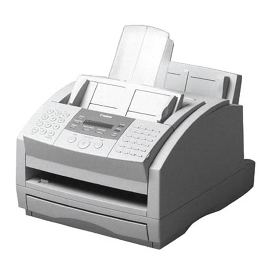
FAX-L350 Chapter 1: General Description 3. OVERVIEW 3.1 External View Front View PAPER REST SUPPORT TRAYS MULTI-PURPOSE TRAY AUTOMATIC PAPER GUIDE DOCUMENT FEEDER (ADF) RELEASE LATCH FACE-DOWN DELIVERY SLOT DOCUMENT GUIDES FRONT COVER OPERATION PANEL PAPER DELIVERY SELECTOR FACE-UP DELIVERY SLOT PAPER CASSETTE EXTENSION TRAY Figure 1-3 External View (1) -
Page 24: Inside View
FAX-L350 Chapter 1: General Description Inside View FX-3 TONER CARTRIDGE COMPARTMENT TRANSFER CHARGING ROLLER PAPER RELEASE LEVER FIXING ASSEMBLY FRONT COVER Rear View REAR COVER POWER CONNECTOR BI-DIRECTIONAL PARALLEL PORT TELEPHONE LINE JACK HANDSET JACK EXTENSION PHONE JACK Figure 1-4 External View (2) 1-11... -
Page 25: Operation Panel
FAX-L350 Chapter 1: General Description 3.2 Operation Panel The Operation Panel LCD display Document feed lever In Use/Memory lamp R button Alarm lamp Coded Speed Dial/ One-Touch Directory button Speed Dial buttons FAX-L350 In Use / Memory Coded Dial / Directory Alarm Receive Mode Resolution... - Page 26 FAX-L350 Chapter 1: General Description In Use/Memory lamp Lights when the telephone line in being used or a document has been received in memory Alarm lamp This lamp flashes when an error occurs, or when the FAX-L350 is out of paper or toner. One-Touch Speed Dial buttons Use these buttons for One-Touch Speed dialing.
-
Page 27: Option
FAX-L350 Chapter 1: General Description Special Function Buttons (One-Touch Speed Dial panel open) Data Delayed Memory Polling Registration Transmission Reference Repor D.T. Tone/ Space Clear Data Registration button Use this button to register user's data, speed dialing, and other important settings for sending and receiving. Delayed Transmission button Press this button to register a time for delayed sending. -
Page 28: Consumable
FAX-L350 Chapter 1: General Description 3.3 Option Handset Kit 3.4 Consumable Toner cartridge FX3 cartridge is used. 1-15... -
Page 29: Dimensions
FAX-L350 Chapter 1: General Description 4. DIMENSIONS 30” (764 mm) 19” (483 mm) SIDE VIEW 14.2” (361 mm) BOTTOM VIEW 30” (764 mm) 19” (483 mm) Figure 1-8 Dimensions 1-16... - Page 30 FAX-L350 Chapter 1: General Description his page intentionally left blank 1-17...
-
Page 31: Safety & Precautions
FAX-L350 Chapter 1: General Description 5. SAFETY & PRECAUTIONS 5.1 Personnel Hazards Fixing section frame surface Main motor Document feed motor Fixing ass'y Pressure roller SCNT board PCNT board Lithium battery NCU board Telephone line Power supply unit MCNT board Interface board Figure 1-9 Personnel Hazards (1) 1-18... - Page 32 FAX-L350 Chapter 1: General Description Document feed roller Main motor Separation roller Document eject roller Document feed motor Paper face-down eject roller Transfer charging roller Paper face-up eject roller Pickup roller Paper feed roller Pickup roller Paper feed roller Figure 1-10 Personnel Hazards (2) 1-19...
-
Page 33: Electrical Shock
FAX-L350 Chapter 1: General Description 5.1.1 Electrical shock Electrical shock hazard • To prevent electrical shock, be sure to disconnect the power cord and modular jack before disassembly. • Remove grounding wrist straps before servicing this unit while the FAX’s power is on. Otherwise, electrical shock may occur. -
Page 34: Moving Parts
FAX-L350 Chapter 1: General Description 5.1.4 Moving parts Moving parts To prevent mishaps due to moving or rotating parts during servicing, be sure to disconnect the power cord before disassembly. 5.1.5 LASER beams This fax is a Class 1 Laser Product as defined in the EN60825 (IEC825) Radiation Safety of laser products, equipment classification, requirements and user’s guide. -
Page 35: General Cautions
For all service, contact your local authorized Canon dealer or the Canon help line. Always follow all warnings and instructions marked on the FAX-L350. - Page 36 Do not allow small objects (such as pins, paper clips, or staples) to fall into the FAX-L350. If something does fall into it, unplug the unit immediately and call your local authorized Canon dealer or the Canon help line. Do not plug the power cord into an uninterruptible power supply (UPS).
- Page 37 FAX-L350 Chapter 1: General Description Unplug the FAX-L350 and contact your local authorized Canon dealer or the Canon help line in any of these situations: If the power cord or plug is damaged or frayed. If liquid spills into the unit, or if it is otherwise exposed to rain or liquids.
- Page 38 FAX-L350 Chapter 1: General Description Choosing a Location for our FAX-L350 Before unpacking your FAX-L350, follow these guidelines to choose an appropriate location for the unit. Please eview the information provided in "Safety Instructions" on pages 1-22 to 1-24, to make sure you are installing your FAX-L350 for safe use.
-
Page 39: Connecting The Power Cord
FAX-L350 Chapter 1: General Description Connecting the Power Cord Follow these guidelines when connecting your FAX-L350 to a power source: The FAX-L350 is intended for domestic use only and requires 200–240V AC. Do not use it outside the country where it was purchased. - Page 40 FAX-L350 Chapter 1: General Description Connect the power cord as follows: 1. Plug the supplied power cord into the power connector on the back of the FAX-L350. 2. Plug the other end of the power cord into the outlet. The FAX-L350 has no power switch, so its power is on as long as it is plugged in.
-
Page 41: Making Connections
Centronics-compatible parallel interface cable from your dealer. For best results, use a cable that is no longer than 6.6 feet (2 meters). Canon recommends that you use a cable that complies with IEEE 1284. Contact your local authorized Canon dealer if you need help in selecting a cable. -
Page 42: Toner Cartridge Cautions
FAX-L350 Chapter 1: General Description 5.2.2 Toner cartridge cautions a) Handling the toner cartridge The Toner Cartridge Handling and Storing Cartridges Do not expose the cartridge to direct sunlight or bright light for longer than ve minutes. Do not open the drum protective shutter on the cartridge. If the drum surface is exposed to light and damaged, print quality may deteriorate. - Page 43 FAX-L350 Chapter 1: General Description Store the cartridge in its protective bag. Do not open the bag until you are ready to install the cartridge in the unit. Save the protective bag. You may need to repack and transport the cartridge at a later date.
-
Page 44: Servicing Cautions
FAX-L350 Chapter 1: General Description 5.3 Servicing Cautions 5.3.1 Damage from static charge This unit contains contact sensor and printed circuit boards equipped with ROM, RAM, custom chips, etc. These electronic components are susceptible to damage caused by static charge. When disassembling this unit, take care to prevent static charge. -
Page 45: Printer Section
FAX-L350 Chapter 1: General Description 5.3.3 Printer section a) Transfer charging roller If skin, oil or, the like, gets on the sponge of the transfer charging roller, the rear side of the recording paper can be soiled, and blank patches can occur in printing. During disassembly, hold the transfer charging roller by the shaft and gears at both ends. -
Page 46: Paper Feed Section
FAX-L350 Chapter 1: General Description d) LASER/Scanner unit The LASER/scanner unit cannot be adjusted in the field so do not attempt to disassemble it. Never loosen or remove the screws on the LASER/scanner unit. Doing so might prevent satisfactory print- ing. -
Page 47: Paper Load Section
FAX-L350 Chapter 1: General Description 5.3.5 Paper load section b) Lifting arm position If cassette is removed with the lifting arm raised to clear jam, the cassette cannot be inserted again. If the recording paper cassette is inserted forcibly, the arm may be damaged. To initialize the lifting arm position (move the arm down), turn the power off and on again or Lifting arm Figure 1-22 Lifting arm position... -
Page 48: Replacing Rom
FAX-L350 Chapter 1: General Description 5.3.7 Replacing ROM Observe the following precautions when replacing the ROM on the SCNT board, for example, when replac- ing a defective ROM. a) Preparation Print out all battery backed up data. Reception image data in image memory is erased appox. one hour after power is turned off. b) Replacement (1) Make sure that the power cord is disconnected. -
Page 49: Data-Related Precautions
FAX-L350 Chapter 1: General Description 5.4 Data-related precautions The memory IC on the circuit board stores the user’s registration data and values for various counters, etc., required for servicing. Although this data is normally retained in memory, it can be deleted by mistake. When handling this data during servicing, note the following precautions. - Page 50 FAX-L350 Chapter 1: General Description Reception image data transfer When reception images cannot be output due to printer failure, etc., the image data can be transferred to another fax machine by using the reception image data transfer function. NOTE Memory Reference MEMORY REFERENCE 1.
-
Page 51: Data In The Control Processing Memory (Sram)
FAX-L350 Chapter 1: General Description 5.4.2 Data in the control processing memory (SRAM) SRAM is backed up by a lithium battery. It can retain the stored data for 5 years after the power is turned off. SRAM stores the following data: All the data the user entered with the user data setting, the activity reports and other report-generating data, the redial data containing the redial destinations set with the Redial button, the servicing data set by repair personnel with the service soft switch. -
Page 52: Scnt Board Replacement Precautions
FAX-L350 Chapter 1: General Description 5.4.3 SCNT board replacement precautions Before replacing the SCNT board, print out all of the stored data. The list which output the data that must be entered into the new SCNT board is listed below. User list One-touch speed dialing list Coded speed dialing list... -
Page 53: Data Initialization Through Service Operation
FAX-L350 Chapter 1: General Description 5.4.4 Data initialization through service operation All the data can be initialized with the service data #8 clear operation. For details on the initialization procedure and the data that is erased, see Chapter 3: 5.2 Service Data Settings on Page 3-28. -
Page 54: Protective Mechanism
FAX-L350 Chapter 1: General Description 5.5 Protective Mechanism 5.5.1 Data battery backup function If there is a power outage or if the power is turned off, the data stored in the control memory is retained since the lithium battery function as a data battery backup. For details on the backed up data, see Chapter 1: 5.4 Data-related precautions on Page 1-36. - Page 55 FAX-L350 Chapter 1: General Description 6. QUALIFICATION REQUIRED FOR INSTALLATION WORK The qualifications for installation must satisfy local laws and regulations. 1-42...
- Page 56 Chapter 2 Technical Reference...
- Page 58 FAX-L350 Chapter 2: Technical Reference 1. DRIVE/ELECTRICAL SYSTEM LAYOUT This machine is divided into three mechanisms: scanner section, paper supply section and printer section. In the scanner section, the document feed motor drives the document feed rollers and separation rollers to feed the document from the document feed tray to the document eject slot at the front of the machine.
- Page 59 FAX-L350 Chapter 2: Technical Reference The following eight printed circuit boards are located in this machine: • SCNT board that controls the entire system • NCU board that interfaces with the telephone line • MODULAR board that connects the telephone line and the NCU board •...
- Page 60 FAX-L350 Chapter 2: Technical Reference This page intentionally left blank...
- Page 61 FAX-L350 Chapter 2: Technical Reference 2. SCANNER MECHANISM The scanner section scans documents that are to be sent or copied. Figure 2-3 Scanner Section...
- Page 62 FAX-L350 Chapter 2: Technical Reference Names and functions of parts: 1. Paper Guide When properly adjusted to the width of the documents, the guide will hold the documents in the horizontal direction to prevent them from skewing when fed. 2. Document Feed Motor This motor drives all the rollers in the scanner section.
- Page 63 FAX-L350 Chapter 2: Technical Reference Initializing the upper document feed roller When the separation roller starts to rotate, the position of the upper document feed roller is simultaneously initialized to raise the document stopper. Initialization is carried out when NOTE the power is turned ON, when documents are inserted and when documents are ejected.
- Page 64 FAX-L350 Chapter 2: Technical Reference This page intentionally left blank...
- Page 65 FAX-L350 Chapter 2: Technical Reference 3. PAPER SUPPLY SECTION The paper supply section separates the sheets of recording paper loaded in the sheet feeder and feeds them to the printer section one sheet at a time. Figure 2-4 Paper Supply Section...
- Page 66 FAX-L350 Chapter 2: Technical Reference Names and functions of parts: 1. Paper Guide (MULTI-PURPOSE TRAY) This guide can be adjusted to the width of the loadable recording paper sizes. It prevents the recording paper from skewing during recording by accurately aligning the paper width. 2.
- Page 67 FAX-L350 Chapter 2: Technical Reference Paper feed jam detection There are two types of paper jam which may occur: a) Paper feed delay jam NOTE The paper feed delay jam occurs if the paper edge sensor does not detect the leading edge of the recording paper within a specific time* (including paper feed jam detection retry time) after the pickup solenoid releases the pickup roller.
- Page 68 FAX-L350 Chapter 2: Technical Reference This page intentionally left blank 2-11...
- Page 69 FAX-L350 Chapter 2: Technical Reference 4. PRINTER SECTION The LASER beam printer engine comprises the following sections. LASER / scanner section Toner cartridge Fixing section Toner transfer section Paper feed / eject section Figure 2-5 Printer Section 2-12...
-
Page 70: Toner Cartridge
FAX-L350 Chapter 2: Technical Reference 4.1 LASER/Scanner Section This section comprises a LASER unit, cylindrical lens, 4-faced polygon mirror, scanner motor, imaging lens, reflection mirror and BD unit. The LASER is driven in accordance with the LASER drive signals that are sent from the PCNT board. -
Page 71: Paper Feed/Eject Section
FAX-L350 Chapter 2: Technical Reference 4.5 Paper Feed/Eject Section After toner is fixed in the fixing section, the recording paper is fed to either the face-up delivery slot or the face-down delivery slot that is switched by the flapper. The user selects the setting of the flapper by the paper delivery selector at the bottom left of the front panel. - Page 72 FAX-L350 Chapter 2: Technical Reference Drum cover shutter If the photosensitive drum is subjected to strong light, optical memory can cause dropout areas or black bands to occur. To prevent the photosensitive drum from strong light, a drum cover shutter is attached. Do not open this cover unless absolutely necessary. Fixing Heater Malfunction The printer controller on the SCNT board detects a fixing heater malfunction in the follow- ing instances.
- Page 73 FAX-L350 Chapter 2: Technical Reference Paper delivery slot switching The paper delivery slot can be switched by the paper delivery selector located at the bottom left on the front of the machine. After fixing, the paper is fed to the flapper, which guides it to one of two delivery slots.
- Page 74 FAX-L350 Chapter 2: Technical Reference 5. ELECTRIC CIRCUIT 5.1 Component Block Diagram 16M bit (SOC1) DRAM 64M bit (IC9) Data Bus, MD7-MD0 Figure 2-7 Block Diagram 2-17...
-
Page 75: Circuit Board Components
FAX-L350 Chapter 2: Technical Reference 5.2 Circuit Board Components a) System control section The system controller is made up of the following components, and controls the entire fax system. a-1) MPU (Micro Processor Unit) (IC26) The main functions of the NEC µPD703102GJ-A33 MPU are as follows: •... - Page 76 FAX-L350 Chapter 2: Technical Reference c) Document scanning section c-1) System controller (IC10) The system controller IC include image processing function (UHQ) are as follows: • Serial-to-parallel conversion • A/D conversion Input signals from the contact sensor are A/D converted. •...
-
Page 77: Flow Of Image Signals
FAX-L350 Chapter 2: Technical Reference 5.3 Flow of Image Signals a) G3 transmission (1) With the LED as a light source, the image is scanned by the contact sensor, and analogue image data sent to the SCNT board. (2) The System controller IC (Internal UHQ unit) converts analogue image data from the contact sensor to digital image data. -
Page 78: Ncu Board
FAX-L350 Chapter 2: Technical Reference b) G3 Reception (1) Image signals received by L1, L2, pass through the hybrid circuit in the NCU, and are amplified. The modem demodulates these image, and writes them to the DRAM. (2) The MPU decodes the demodulated image data, checks errors, stores it in the DRAM, encodes the data and rewrites it into the DRAM. -
Page 79: Fax/Tel Switching
FAX-L350 Chapter 2: Technical Reference 6. COMMUNICATION SYSTEM OPERATIONS 6.1 FAX/TEL Switching This fax is set to automatically switch between fax and telephone, on the same telephone line. If the other party is a fax, the fax is received automatically, and if the other party is a telephone, the alarm in the main unit is rung to alert the user. -
Page 80: Answering Machine Connection
FAX-L350 Chapter 2: Technical Reference 6.2 Answering Machine Connection This connection is for effective use of an answering machine connected to the extension telephone jack. If the other party is a telephone, the answering telephone records the message, and if the other party is a fax, the fax receives automatically. -
Page 81: High-Speed Transmission
FAX-L350 Chapter 2: Technical Reference 7. NEW FUNCTION 7.1 High-speed Transmission The image transmission time is reduced drastically compared with the previous models by the V.34 modem (maximum transmission speed 33600 bps) recommended by ITU-T. 7.1.1 V.8/V.34 protocol a) Outline •... - Page 82 FAX-L350 Chapter 2: Technical Reference 1. The V.34 protocol uses ECM. If the ECM SW in user data is set to OFF, the V.8 protocol is not executed. Therefore, the V.34 protocol is not used, and V.17 or a lower protocol is selected.
- Page 83 FAX-L350 Chapter 2: Technical Reference b) Typical protocol Declares the usable modulation Connected to the line mode. Network interaction Declares that V.34 capability exists ANSam (Phase 1) on each machine, and transfers the (See page 2-27) V.34 procedures with phase 2. INFO0c INFO0a After declaring the modem's...
- Page 84 FAX-L350 Chapter 2: Technical Reference b-1) Network interaction (Phase 1) The V.8 protocol is used as the startup protocol for high-speed modem V.34. The V.8 protocol determines the best modulation method (V-series modem mode) that is available be- tween the transmitter and receiver. •...
- Page 85 FAX-L350 Chapter 2: Technical Reference b-2) Probing (Phase 2) The line characteristics are measured and modulation-related parameters, such as symbol rate, are set. • Transmitter Signal Abbreviation Meaning Remarks INFO sequence INFO0c Indicate modem capabilities, Transmission such as baud rate and fre- speed: 600bps quency transmission function (two frequency bands used to...
- Page 86 FAX-L350 Chapter 2: Technical Reference b-3) Primary channel equalizer training (Phase 3) Filters, such as equalizers, are trained (adjusted) with the parameters set in phase 2. • Transmitter Signal Abbreviation Meaning Remarks S signal Short training The phase of S is S signal shifted from the phase of S.
- Page 87 FAX-L350 Chapter 2: Technical Reference b-5) Control channel The conventional T.30 protocol is executed. The transmission speed is 600bps. • Transmitter Signal Abbreviation Meaning Remarks Flag flags Maintain synchronization 7E (H) Non-standard facilities Receive NSF from the other set-up party, select an available mode from it, and instruct reception.
- Page 88 FAX-L350 Chapter 2: Technical Reference b-6) Primary channel resyncronization procedure Training is performed with the parameters set in phase 4. The transmission speed is 1200bps. • Transmitter Signal Abbreviation Meaning Remarks S signal Short training The phase of S is S signal shifted from the phase of S.
- Page 89 FAX-L350 Chapter 2: Technical Reference b-8) Control channel resyncronization procedure (Communication end procedure) Protocol for terminating transmission. The transmission speed is 1200bps. • Transmitter Signal Abbreviation Meaning Remarks Sh signal Short training Sh signal ALT signal E sequence End of procedures PPS-EOP One page is transmitted.
- Page 90 FAX-L350 Chapter 2: Technical Reference c) Examples of sequences The signals in the shaded areas are important in the protocol. c-1) Late start Since the receiver cannot detect the CM signal while sending the ANSam signal, it sends the DIS signal containing the "V.8 protocol"...
- Page 91 FAX-L350 Chapter 2: Technical Reference c-2) Between-page sequence The transmitter sends image data, then the PPS-MPS signal in the same as for the T.30 protocol. The receiver sends the MCF signal to receive the next page. Image data Turn-off PPS-MPS flags flags flags...
- Page 92 The transmitter sends PPS-EOM and the receiver sends the MCF signal. Then the receiver sends the DIS signal and the transmitter sends the DCS signal to change the mode. Image data Turn-off PPS-EOM flags flags When Canon fax flags machines communicate with each other, a special procedure is used, so this protocol is comitted. flags...
- Page 93 FAX-L350 Chapter 2: Technical Reference c-4) Image transmission speed change from the receiver The receiver returns to the PPh signal in response to the Sh signal from the transmitter. The image transmission speed is then determined by the MPh sequence sent from both modems. Image data Turn-off...
- Page 94 FAX-L350 Chapter 2: Technical Reference c-5) Image transmission speed change from the transmitter The transmitter sends image data, and then the PPh signal, and the receiver returns the PPh signal to the transmitter. The image transmission speed is then determined by the MPh sequence sent from both modems.
- Page 95 FAX-L350 Chapter 2: Technical Reference 7.2 JBIG Image Compression Encoding Method 7.2.1 Outline of the JBIG image compression encoding method The JBIG Image Compression Encoding Method is recommended in ITU-T T.82/T.85 as a new bi-level (bi- level: White and Black) image compression encoding method developed by JBIG (Joint Bi-level Image experts Group).
-
Page 96: Single Progression Sequential Bi-Level Image Compression Method
FAX-L350 Chapter 2: Technical Reference The characteristics of Progressive Bi-level Image Compression are explained below as a reference. First of all, after the original image has been read in at high resolution, it is converted to low resolution, and this low resolution image data proceeds to be encoded NOTE (compressed). -
Page 97: Encoding Method
FAX-L350 Chapter 2: Technical Reference 7.2.3 Encoding method In the JBIG encoding used in the Single Progression Sequential Bi-level Image Compression Method, uses in the encoder shown below to encode to the original the results of comparison of the line currently being processed and the previous line, as well as the predicted value of an image pixel (white or black) used in a model template. - Page 98 FAX-L350 Chapter 2: Technical Reference b) In the model template, the combination (10-bit pixel pattern) of 10 pixels is output to the arithmetic encoding section using the template shown below (inside the bold outline). All of the 10-bit pixel patterns inside this template exist in the study table. This 10-bit pixel pattern is used by the arithmetic encoding section to refer to the predicted value of the pixel and the status number in the study table which correspond to the 10-bit pixel pattern.
- Page 99 FAX-L350 Chapter 2: Technical Reference 3-line model template 2-line model template Figure 2-19 Positions of Pixels in Model Template Table 2-1 Study Table (Initial values) Predicted Pixel pattern in the model template Status No. value of (ST) pixel 0 (white) 000h 0 (white) 001h...
- Page 100 FAX-L350 Chapter 2: Technical Reference Example: A brief explanation of how the study table works is given below. It is assumed that each of the model template pixels 1~10 in the image below are white. 1. In this case, the model template pixel pattern is 000h. 2.
- Page 101 FAX-L350 Chapter 2: Technical Reference This table shows probability of accuracy/inaccuracy in the form of a range, according to the accurate/inaccurate results of a given status prediction value. The plan of the probability estimation table is such that if the prediction is accurate, the NOTE range of the next status number will be smaller than would be the case in an inaccurate prediction.
- Page 102 FAX-L350 Chapter 2: Technical Reference The concept of arithmetic encoding is simply explained below. The following assumptions are made in order to make the explanation easy to understand. The probability of accuracy will be 50%, and the probability of inaccuracy will be 50%. The area of accuracy will be MPS, and the area of inaccuracy will be LPS.
- Page 103 FAX-L350 Chapter 2: Technical Reference Next, the encoding for continuous accurate predictions will be simply explained. The assumptions below will be made for easy understanding. The value of an accurate LSZ will be decimal 100 in all statuses. Range A will have limits of decimal 8000~10000 , and when range A is below decimal 8000 , the lead encoding bit will be pushed out, and the encoded image data will be output.
-
Page 104: Construction Of Image Data With Jbig Image Compression Encoding
FAX-L350 Chapter 2: Technical Reference 7.2.4 Construction of image data with JBIG image compression encoding Images are encoded in block units called stripes, as shown in the figure below. Document width (XD) Header Floating marker code Stripe Stripe length (L0) Floating marker code Stripe... -
Page 105: Explanation Of Bi-Level Image Header Section (Bih)
FAX-L350 Chapter 2: Technical Reference 7.2.5 Explanation of bi-level image header section (BIH) The BIH is shown in the construction figure below. It designates the image size, number of lines per stripe, model template, etc. BIH (Bi-level Image Header) FILL Orber Option DPTABLE... -
Page 106: Explanation And Parameters For Each Symbol Used In Bih
FAX-L350 Chapter 2: Technical Reference 7.2.6 Explanation and parameters for each symbol used in BIH The 0x of each parameter shows that the following integers are hexadecimal. Symbol Meaning Parameter Reference Initial layer to be transmitted 0x00 fixed Number of differential layers 0x00 fixed Number of bit planes 0x00 fixed... -
Page 107: Explanation Of Bi-Level Image Data (Bid) Section
FAX-L350 Chapter 2: Technical Reference 7.2.7 Explanation of bi-level image data (BID) section BID is as shown in the construction figure below, and consists only of the number of stripes. BID is constructed by the connection of the floating marker code and the section which includes the actual image data encoded with JBIG image compression encoding, called SDE (Stripe Data Entity). - Page 108 FAX-L350 Chapter 2: Technical Reference COMMENT (Private comment: 0x07) An optional comment may be added. ESC 0x07 Lc:Comment length NEWLEN (New length: 0x04) Redefine the document length. Only usable when VLENGTH=ON. ESC 0x04 YD:Document length RESERVE (Reserve: 0x01) Only usable for characteristic use. ESC 0x01 b) Stripe data section PSCD (Protected stripe encoding data)
- Page 109 FAX-L350 Chapter 2: Technical Reference This page intentionally left blank 2-52...
- Page 110 Chapter 3 Maintenance and Service...
- Page 112 FAX-L350 Chapter 3: Maintenance and Service 1. MAINTENANCE LIST 1.1 Consumables Level Consumable When When “REPLACE CARTRIDGE” is displayed. User Toner cartridge (FX3) Service technician None 1.2 Cleaning Level Location When User Main unit outer covers When dirty. Separation roller When document separation/ feed performance falls.
-
Page 113: Periodic Inspection
FAX-L350 Chapter 3: Maintenance and Service Level Location When Service technician Fixing entrance guide When marks on back of paper, irregular/smudged black vertical line, paper jam, wrinkles in copied or received images. Paper face-up eject When paper jams occur during copying or roller receiving. -
Page 114: Adjustment Items
FAX-L350 Chapter 3: Maintenance and Service 1.5 Adjustment Items None 1.6 General Tools Tool Phillips screwdriver Removing/inserting screws Flat bladed screwdriver Removing/inserting screws Precision flat bladed screwdriver Removing plastic tabs Tweezers Removing coil spring Pliers, needle nose Driving retaining ring Lint-free paper Clean transfer charging roller, fixing film Isopropyl alcohol... -
Page 115: Main Unit Outer Covers
FAX-L350 Chapter 3: Maintenance and Service 2. HOW TO CLEAN PARTS 2.1 Main Unit Outer Covers Lightly wipe the unit’s outer causing with a clean, soft, lint-free cloth moistened with water or diluted dishwashing detergent solution. 2.2 Separation Roller Wipe with a soft, dry clean cloth. 2.3 Separation Guide Wipe with a dry clean soft cloth. - Page 116 FAX-L350 Chapter 3: Maintenance and Service Separation guide Front cover Separation roller (Scanner section) Paper feed guide White sheet Scanning glass Figure 3-1 Cleaning Location 1...
-
Page 117: Paper Pickup Roller
FAX-L350 Chapter 3: Maintenance and Service 2.7 Paper Pickup Roller Using lint-free paper dipped in isopropyl alcohol, wipe and dirt off the paper pickup roller. 2.8 Transfer Charging Roller Wipe with lint-free paper and remove any toner or paper debris. Do not touch or hold the sponge section of the transfer charging roller. - Page 118 FAX-L350 Chapter 3: Maintenance and Service Document feed roller Transfer charging roller Document eject roller Paper pickup roller Separation pad Paper pickup roller Paper face-up eject roller Flapper Pressure roller High voltage terminal Static charge Fixing ass'y eliminater Fixing entrance guide Figure 3-2 Cleaning Location 2...
-
Page 119: Replacing Parts
FAX-L350 Chapter 3: Maintenance and Service 3. REPLACING PARTS & ADJUSTMENTS 3.1 Replacing Parts For details on the disassembly/assembly procedure when replacing parts, refer to the Parts Catalog (separate). Illustrations in the Parts Catalog are drawn in the order in which parts are disassembled. The Parts Catalog also shows enlarged drawings or supplementary illustrations for parts requiring caution during disassembly and assembly. -
Page 120: Troubleshooting Index
FAX-L350 Chapter 3: Maintenance and Service 4. TROUBLESHOOTING 4.1 Troubleshooting Index Use the troubleshooting index below to investigate the cause of a problem and refer to the specified page for countermeasures. Problem • General errors Page 3-18 • The unit does not power on. •... - Page 121 FAX-L350 Chapter 3: Maintenance and Service • Scanning problems (Evaluation criteria: Test printing is good, but the copied image is poor.) Page 3-25 • The document is not fed. The document feed motor does not run. The document slips against the rollers. The document does not separate.
- Page 122 FAX-L350 Chapter 3: Maintenance and Service "DOC. TOO LONG" (#003) Cause: The document is longer than 39.4"(1m). Solution: Use a copy machine to make a reduced copy of the document, then send again. Cause: It took more than 32 minutes to send, copy, a document or receive a document. Solution: Divide the document and send or copy each part separately.
-
Page 123: Error Codes
FAX-L350 Chapter 3: Maintenance and Service "START AGAIN" Cause: An error occurred on the phone line or in the system. Solution: Start the procedure again from the beginning. "LOAD PAPER" Cause: The fax is out of paper. Solution: Add more paper to the paper tray. "CHECK COVER/CART"... - Page 124 FAX-L350 Chapter 3: Maintenance and Service b) Error code countermeasures The following item c) lists all the error codes which the unit can display. The separate G3 Facsimile Error Code List (Rev. 1) does not specify the countermeasures for resolvable error codes. Also refer to this list when an error code appears.
- Page 125 FAX-L350 Chapter 3: Maintenance and Service c) ERROR CODE LIST for FAX-L350 The error codes used for this fax are as follows. Codes listed as “New” in the list below indicate new error codes, or codes whose measures differ from those listed in the separate document G3 Facsimile Error Code List (Rev.1) .
- Page 126 FAX-L350 Chapter 3: Maintenance and Service Tx or Rx Definition ##284 [ TX DCN Reception after TCF Transmission ##285 [ TX DCN Reception after EOP Transmission ##286 [ TX DCN Reception after EOM Transmission ##287 [ TX DCN Reception after MPS Transmission ##288 [ TX Receive Signals Other than PIN, PIP, MCF, RTP or RTN after EOP Trans-...
- Page 127 FAX-L350 Chapter 3: Maintenance and Service Tx or Rx Definition ##768 [ TX Exceed Protocol Retransmission Limit or T5 Time (60 seconds) after PPS-EOP Transmission during ECM Tx ##769 [ TX Exceed Retransmit Protocol after PPS-EOP Transmission during ECM ##770 [ TX Exceed Repeat Protocol Limit Due to Failure to Receive Significant Sig- nals after Transmitting EOR-NULL during ECM Tx...
- Page 128 FAX-L350 Chapter 3: Maintenance and Service d) New error codes and recovery methods There is no new error code in this model. Note, however, the following supplementary information, as the machine requires different actions than the existing models to correct: ##322 [TX/RX] Fixing heater temperature abnormality Cause: Internal unit defect.
- Page 129 FAX-L350 Chapter 3: Maintenance and Service 4.3 Errors not Shown on the Display 4.3.1 General errors • The unit does not power on. (Evaluation criteria: Look at the actual unit.) (1) Check the power cord connection. (2) Check the connection between the SCNT board (J2) and power supply unit (J201). (3) Check the power supply unit's fuse (FU101).
-
Page 130: Printing Problems
FAX-L350 Chapter 3: Maintenance and Service 4.3.2 Printing problems • Faulty printing (Evaluation criteria: Test print is faulty.) • The paper is not fed correctly. (Evaluation criteria: Look at the actual unit.) The main motor does not run. (1) Check the voltage (+12 V) at both terminals of C501 located on the MCNT board. (2) Check the main motor's resistance. - Page 131 • Poor printing quality (Evaluation criteria: Check the test print image's faults.) Before checking for the cause of print defects, check whether the user uses Canon-recommended paper and stores it correctly. If the problem is solved by using the recommended paper, the customer should be advised to use the recommended paper and store it correctly.
- Page 132 FAX-L350 Chapter 3: Maintenance and Service • Light Solutions: (1) Remove the toner cartridge and shake it lightly five or six times. (2) Verify that user setting “ECONOMY PRT” is not “ON”. (3) Replace the toner cartridge. (4) Open the front cover during printing, and remove the toner cartridge. Open the cartridge drum cover shutter manually, and check whether the toner image on the photosensitive drum is transferred onto the paper.
- Page 133 FAX-L350 Chapter 3: Maintenance and Service • Marks on back of paper Solutions: (1) Copy a few white paper documents. (2) If the marks are at intervals of approx. 50mm (1.96"), clean the transfer charg- ing roller, but if they are at intervals of approx. 63mm (2.48"), clean the pressure roller.
- Page 134 FAX-L350 Chapter 3: Maintenance and Service • White vertical lines Solutions: (1) Remove the toner cartridge and shake it lightly five or six times. (2) Open the toner cartridge drum shutter and if there are vertical white lines on the photosensitive drum, replace the toner cartridge.
- Page 135 FAX-L350 Chapter 3: Maintenance and Service Checking the fixing nip width Improperly set fixing nip may cause a fixing ass’y problem. The fixing ass’y is not designed to allow adjustment of the nip. Check the fixing ass’y nip by using the following procedure. NOTE (1) Either take along one or two all-black copies of A4 or letter size made with a copier, or make one using a copier at the customer site.
-
Page 136: Scanning Problems
FAX-L350 Chapter 3: Maintenance and Service 4.3.3 Scanning problems • Faulty scanning (Evaluation criteria: Test print is good, but the copied image is poor.) • The document is not fed. The document feed motor does not run. (Evaluation criteria: Check it visually.) (1) Check the voltage (+12 V) at both terminals of C501 located on the MCNT board. - Page 137 FAX-L350 Chapter 3: Maintenance and Service • The reading image is abnormal. (Evaluation criteria: Check the copy image's faults.) Nothing is printed. (1) Check the connection between the contact sensor and SCNT board (J1). (2) Replace the contact sensor unit. (3) Replace the SCNT board.
- Page 138 FAX-L350 Chapter 3: Maintenance and Service 5. SERVICE SWITCHES 5.1 Hardware Switches There is a slide switch on the NCU board that must be set for each country. SW No. Nation U.K., FRN, AE, AUS, CHINA, N.Z. SWEDEN OTHERS (in CENV territory) Figure 3-8 Slide Switch Location on NCU and Switch Settings 3-27...
- Page 139 FAX-L350 Chapter 3: Maintenance and Service 5.2 Service Data Settings Service data can be checked and changed with items on display menus. The default values of the SSSW/ parameters available in this fax machine are shown in this Chapter, 5.2.3 Service data settings in this manual.
- Page 140 FAX-L350 Chapter 3: Maintenance and Service 5.2.2 Service data registration/setting method Service data can be registered and set by the following operations: 25/09/1999 SAT 10:23 Standby (Time and Receive mode Display) Fax Tel STANDARD (1) User data mode selection Press the Data registration. REGISTRATION 1.
- Page 141 FAX-L350 Chapter 3: Maintenance and Service 5.2.3 Service data settings Service data 7 6 5 4 3 2 1 0 #1 SSSW Error management SW01 0 0 – 1 0 – 0 0 (Service soft switch setting) Memory clear list output setting SW02 –...
- Page 142 FAX-L350 Chapter 3: Maintenance and Service #2 MENU Not used (Menu switch settings) Not used Not used Not used NL equalizer setting DIAL Line monitor setting SERVICEMAN Transmission level setting 10 (0~15) V.34 Baud rate 3429 baud 3200 baud 3000 baud 2800 baud 2743 baud 2400 baud...
- Page 143 FAX-L350 Chapter 3: Maintenance and Service #3 NUMERIC Param. (Numeric parameter settings) Default Range Not used 10 (10%) (1~99) RTN signal transmission condition (1) 15 (15 lines) (2~99) RTN signal transmission condition (2) 12 (12 times) (1~99) RTN signal transmission condition (3) Pause time for NCC (before the ID code) Pause time for NCC (after the ID code) 350 (3500 ms)
- Page 144 FAX-L350 Chapter 3: Maintenance and Service #3 NUMERIC PARAM. (Numeric parameter settings) The relationship between the settings and the detection levels is as follows: NOTE Parameter 24 0: Not used 1: Not used 2: Not used 3: Not used 4: Not used 0 dBm 6: -1 dBm 7: -2 dBm...
- Page 145 FAX-L350 Chapter 3: Maintenance and Service #4 NCU TONE/PULSE (NCU settings) DIAL TONE 2nd DIAL TONE BUSY TONE 0 BUSY TONE 1 REORDER TONE MULTI AUTO RX CNG DETECT SPECIAL RKEY PBX DIAL TONE PBX BUSY TONE EUROPE #5 TYPE (Type setting) U.
- Page 146 FAX-L350 Chapter 3: Maintenance and Service 1. SSSW #7 PRINTER (Printer function settings) Not used SW01 – – – – – – – – SW02 – – – – – – – – Not used SW03 – – – – –...
- Page 147 FAX-L350 Chapter 3: Maintenance and Service Dialling data initialization #8 CLEAR (Data initialization mode USER SW User data and service data #1 to #3 settings) initialization SERVICE SW User data and service data #1 to #3 and #6 to #7 initialization #4 NCU setting data initialization SERVICE DATA Data on system dump list initialization...
- Page 148 FAX-L350 Chapter 3: Maintenance and Service 5.2.4 Explanation of service data a) SSSW (Service Soft Switch settings) The items registered and set by each of these switches comprise 8-bit switches. The figure below shows which numbers are assigned to which bits. Each bit has a value of either 0 or 1. SW01 Figure 3-16 Bit Switch Display See the chart in the service data shown in this Chapter, 5.2.3 Service data settings to see effective bits...
-
Page 149: New Sssws/Parameters Added To This Model
FAX-L350 Chapter 3: Maintenance and Service 5.2.5 New SSSWs/parameters added to this model #1 SSSW (service soft switch setting) SW01 (service soft switch 01: error management) Function Service error code Output Not output Error dump list Output Not output Not used Copy function 4 (New) ##300 series service error code Output... - Page 150 FAX-L350 Chapter 3: Maintenance and Service #1 SSSW (service soft switch setting) SW18 (service soft switch 18: communication trouble solutions settings (2)) Function 0 (New) Detection of carrier disconnection Detect Do not detect between the DCS signal and the TCF signal 1 (New) Waiting time for carrier 600 ms 300 ms...
- Page 151 FAX-L350 Chapter 3: Maintenance and Service #1 SSSW (service soft switch setting) SW28 (service soft switch 28: V.8/V.34 protocol settings) Function 0 (New) Caller V.8 protocol 1 (New) Called party V.8 protocol 2 (New) Caller V.8 protocol late start 3 (New) Called party V.8 protocol late start No 4 (New) V.34 reception fallback Prohibited Not prohibited...
- Page 152 FAX-L350 Chapter 3: Maintenance and Service #2 MENU Function Selecting range Default setting V.34 max. baud rate 2400 ~ 3429 3429 (3429 baud) V.34 max. transmission speed 24 ~ 33.6 33.6 (33600 bps) [No. 08] Select the maximum baud rate for V.34 transmission: 3429, 3200, 3000, 2800, 2743, and 2400. [No.
- Page 153 FAX-L350 Chapter 3: Maintenance and Service #7 PRINTER service soft switch setting SW04 (switch 04: reduction/cassette selection settings) Function 0 (New) When LTR/LGL specification is received by DCS, the cassette is selected according to the specification Not used Not used Not used Not used Not used...
- Page 154 FAX-L350 Chapter 3: Maintenance and Service SSSW Default Setting TYPE EUROPE U.K. SWEDEN SWISS AUSTRIA DENMARK #1 SSSW SW01 00010000 00010000 00010000 00010000 00010000 00010000 SW02 00000000 00000000 00000000 00000000 00000000 00000000 SW03 00000000 00000000 00000000 00000000 00000000 00000000 SW04 10000000 10000000 10000010...
- Page 155 FAX-L350 Chapter 3: Maintenance and Service SSSW Default Setting TYPE NORWAY HOLLAND BELGIUM AUSTRALIA FINLAND N.Z. #1 SSSW SW01 00010000 00010000 00010000 00010000 00010001 00010000 SW02 00000000 00000000 00000000 00000000 00000000 00000000 SW03 00000000 00000000 00000000 00000000 00000000 00000000 SW04 10000010 10000010 10000000...
- Page 156 FAX-L350 Chapter 3: Maintenance and Service SSSW Default Setting TYPE ITALY SPAIN PORTUGAL IRELAND HONG KONG MALAYSIA #1 SSSW SW01 00010000 00010000 00010000 00010000 00010000 00010000 SW02 00000000 00000000 00000000 00000000 00000000 00000000 SW03 00000000 00000000 00000000 00000000 00000000 00000000 SW04 10000010 10000010...
- Page 157 FAX-L350 Chapter 3: Maintenance and Service SSSW Default Setting TYPE HUNGARY CHINA GERMAN SINGAPORE CZECH #1 SSSW SW01 00010000 00010000 00010000 00010000 00010000 00010000 SW02 00000000 00000000 00000000 00000000 00000000 00000000 SW03 00000000 00000000 00000000 00000000 00000000 00000000 SW04 10000000 10000000 10000000 00000010...
- Page 158 FAX-L350 Chapter 3: Maintenance and Service SSSW Default Setting TYPE SLOVENIA FRANCE ASIA #1 SSSW SW01 00010000 00010000 00010000 SW02 00000000 00000000 00000000 SW03 00000000 00000000 00000000 SW04 10000000 00000010 10000000 SW05 00000000 00000000 00000000 SW06 10000000 10000000 10000000 SW07 00000000 00000000 00000000...
- Page 159 FAX-L350 Chapter 3: Maintenance and Service SSSW Default Setting TYPE EUROPE U.K. SWEDEN SWISS AUSTRIA DENMARK #3 NUMERIC Param 5500 5500 5500 5500 5500 5500 3500 3500 3500 3500 3500 3500 1310 1310 1310 1310 1310 1310 #5 TYPE EUROPE U.K.
- Page 160 FAX-L350 Chapter 3: Maintenance and Service SSSW Default Setting TYPE NORWAY HOLLAND BELGIUM AUSTRALIA FINLAND N.Z. #3 NUMERIC Param 5500 5500 5500 5500 5500 5500 3500 3500 3500 3500 3500 3500 1310 1310 1310 1310 1310 1310 #5 TYPE NORWAY HOLLAND BELGIUM AUSTRALIA...
- Page 161 FAX-L350 Chapter 3: Maintenance and Service SSSW Default Setting TYPE ITALY SPAIN PORTUGAL IRELAND HONG KONG MALAYSIA #3 NUMERIC Param 5500 5500 5500 5500 5500 5500 3500 3500 3500 3500 3500 3500 1310 1310 1310 1310 1310 1310 #5 TYPE ITALY SPAIN PORTUGAL...
- Page 162 FAX-L350 Chapter 3: Maintenance and Service SSSW Default Setting TYPE HUNGARY CHINA GERMAN SINGAPORE CZECH #3 NUMERIC Param 5500 3500 4300 9000 5500 5500 3500 3500 3500 3500 3500 3500 1310 1310 1200 1310 1310 1310 #5 TYPE HUNGARY CHINA GERMAN SINGAPORE CZECH...
- Page 163 FAX-L350 Chapter 3: Maintenance and Service TYPE SLOVENIA FRANCE ASIA #3 NUMERIC Param 5500 5500 5500 3500 3800 3500 1310 1310 1310 #5 TYPE SLOVENIA FRANCE ASIA 3-52...
-
Page 164: Service Test Functions
FAX-L350 Chapter 3: Maintenance and Service 6. TEST FUNCTIONS 6.1 Service Test Functions The fax functions for testing individual operations, such as below. See Page 3-36 for details of entering the test mode. To leave the test mode, press the CLEAR button. 6.1.1 Test mode overview Test mode can be executed by following the menu items from the display. -
Page 165: Test Mode Flowchart
FAX-L350 Chapter 3: Maintenance and Service 6.1.2 Test mode flowchart TEST MODE ‘ ’ indicates that these items are not used in the field. [1] D-RAM See Page 3-55 [2] CS [3] PRINT [0] CG [1] WHITE See Page 3-56 [2] BLACK [3] STRIPES [4] CHECKERS... -
Page 166: D-Ram Tests
FAX-L350 Chapter 3: Maintenance and Service 6.1.3 D-RAM tests Pressing the 1 button from the test mode menu selects the D-RAM tests. D-RAM Test 1 writes data to the entire D-RAM region and reads it out to check that operations are correct. D-RAM Test 2 just reads data at high speed. - Page 167 FAX-L350 Chapter 3: Maintenance and Service 6.1.4 Print The Print Test menu is selected by pressing the 3 key from the test mode menu. In this test, various print patterns are output from the printer. As service print patterns, press numeric button 2 from the Print Test menu to select “3-2: Black”...
-
Page 168: Modem And Ncu Tests
FAX-L350 Chapter 3: Maintenance and Service 6.1.5 Modem and NCU tests These tests test modem and NCU transmission and reception. The modem tests check whether signals are sent correctly from the modem by comparing the sound of the signals from the speaker with the sounds from a normal modem. - Page 169 FAX-L350 Chapter 3: Maintenance and Service b) G3 signal transmission test The G3 signal transmission test menu is selected by pressing numeric button 4 from the MODEM NCU test menu. The G3 signals below are sent from the modem using the modular jack and the speaker. The frequency can be changed with the numeric buttons.
- Page 170 FAX-L350 Chapter 3: Maintenance and Service d) V.34 G3 signal transmission test The V.34 G3 signal transmission test menu is selected by pressing numeric button 8 from the MODEM NCU test menu. The V.34 G3 signals below are sent from the modem using the modular jack and the speaker by pressing the start key.
-
Page 171: Faculty Tests
FAX-L350 Chapter 3: Maintenance and Service 6.1.6 Faculty tests The faculty tests are selected by pressing numeric button 6 from the test mode menu. These tests check the following faculties of this fax. Test type Overview Sensor tests Test whether the sensors are operating correctly. Operation panel test Tests whether the button switches on the control panel are operating correctly. - Page 172 FAX-L350 Chapter 3: Maintenance and Service 6-3 : SENSOR [1] - - - [5] Pressing the 1 key. DS of DES of DOC A4 DS: Document sensor DES: Document edge sensor on/of: document/no document DOC: Document width sensor A4 (This machine does not have this sensor.) Pressing the 2 key.
- Page 173 FAX-L350 Chapter 3: Maintenance and Service b) Operation panel tests The operation panel test is selected by pressing numeric button 7 from the faculty test menu. This test checks that the display, LED lamps, and buttons on the control panel are operating correctly. b-1) Display test Pressing the START/COPY button from the control panel menu, "H"...
- Page 174 FAX-L350 Chapter 3: Maintenance and Service 6-7:OPERATION PANEL Press Start key. HHHHHHHHHHHHHHHHHHHH H pattern displayed HHHHHHHHHHHHHHHHHHHH Press Start key. All LCD dots displayed Press Start key. 6-7:OPERATION PANEL All LED lamps light up. LED TEST Press Start key. 1 2 3 4 5 6 7 8 9 P R E When a key is pressed, the corresponding character goes out.
- Page 175 FAX-L350 Chapter 3: Maintenance and Service c) Line signal reception test The line detect test menu is selected by pressing numeric button 9 from the faculty test menu. This test checks the operation of the NCU signal sensor and frequency counter. In Menu 1, the CI, status can be detected and in Menu 2 the frequency can be detected at changing detection levels.
- Page 176 FAX-L350 Chapter 3: Maintenance and Service 7. SERVICE REPORT 7.1 Report Output Function 7.1.1 User report output functions The fax can output user reports manually, and some reports can be output automatically using the to user data settings. a) Manual output of reports Report type Operations After pressing the Report button, use the...
- Page 177 FAX-L350 Chapter 3: Maintenance and Service b) Reports which can be output automatically using user data and PC settings Each report written below can be automatically output by specifying “REPORT SETTING” in user data. Transmission report Reception report ROM Version display The ROM version is printed on the top left hand side of the User's data list.
- Page 178 FAX-L350 Chapter 3: Maintenance and Service 7.1.2 Service report output functions The fax outputs current service data settings, and past communications history reports. a) List of service reports The fax outputs the service reports shown below. Report type Operations 1. Service & System list In the service mode, pressing the Report button, then use the 2.
- Page 179 FAX-L350 Chapter 3: Maintenance and Service a-1) System data list This list shows the current settings service data #1~#5, #7 and #9. Figure 3-25 System Data List (page 1 ~ page 4) 3-68...
- Page 180 FAX-L350 Chapter 3: Maintenance and Service Figure 3-26 System Data List (page 5, page 6) “START DATE” records the date when the fax performs its first operation, after shipment from the factory. NOTE 3-69...
- Page 181 FAX-L350 Chapter 3: Maintenance and Service a-2) System dump list Figure 3-27 System Dump List (1/2) 3-70...
- Page 182 FAX-L350 Chapter 3: Maintenance and Service CLEAR DATE : Date on which data was initialized using service data #8 CLEAR, ALL RX/TX : Total number of pages received/transmitted A4/B4/A3/LTR/LGL : Total number of pages transmitted and received for each document size 33600 bps~2400 bps : Total number of pages transmitted and received for each modem speed STD/FINE/SUPER/ULTRA : Total number of pages transmitted and received for each mode...
- Page 183 : Telephone number sent from other party MAKER CODE : Maker code (For details, see Chapter 4: 3. MAKER-CODE on page 4-5 ) [1000 1000] Indicates a Canon fax lower nibble upper nibble RCV V.8 FRAME : Received V.8 protocol signal...
- Page 184 (lower 20 digits) SUBADDRESS : Subaddress number sent from the other party CONNECTION ID : ID sent from the other party, if the other party is a Canon fax START TIME : Communication start date and time (on 24-hour display) USAGE TIME...
- Page 185 (lower 20 digits) SUBADDRESS : Subaddress number sent from the other party CONNECTION ID : ID sent from the other party, if the other party is a Canon fax START TIME : Communication start date time (on 24-hour display) USAGE TIME...
- Page 186 FAX-L350 Chapter 3: Maintenance and Service 8. WIRING DIAGRAM 8.1 Wiring Diagram J203 J102 TB1-1 TB1-2 J009M J008M Contact sensor Figure 3-31 Wiring Diagram 3-75...
- Page 187 FAX-L350 Chapter 3: Maintenance and Service 8.2 Connector Locations and Signal Descriptions SCNT board (J1) Contact sensor sensor Signal name Description VOUT Analog image data — AGND Analog ground — AGND Analog ground +5VA Logic drive voltage VREF Image signal reference voltage Image scan start signal Contact sensor drive clock VLED...
- Page 188 FAX-L350 Chapter 3: Maintenance and Service SCNT board (J3) PCNT board (J1) Signal name Description — Ground RLYD Relay control signal FSRD Fixing heater control signal DVFOT Developing AC bias drive signal TRCRNT Transfer voltage feedback signal TRPWM Transfer positive voltage drive signal TRNFOT Transfer negative voltage drive signal PRACC...
- Page 189 FAX-L350 Chapter 3: Maintenance and Service SCNT board (J403) NCU board (J2) J403 Signal name Description — AGND Ground Not used +12V Analog device, Relay drive voltage — Line monitor signal Telephone line transmission signal Telephone line reception signal SCNT board (J404) NCU board (J1) J404 Signal name...
- Page 190 FAX-L350 Chapter 3: Maintenance and Service SCNT board (J405) NCU board (J6) J405 Signal name Description — Direct current of line detection signal IPSEL1 HIC terminal impedance setting IPSEL2 HIC terminal impedance setting — IPSEL3 HIC terminal impedance setting DCSEL DC registance switching when line is connected DCLIM DC current limitation control signal...
- Page 191 FAX-L350 Chapter 3: Maintenance and Service SCNT board (J501) MCNT board (J502) J501 J502 Signal name Description Phase -A Phase A FSRTH Fixing heater temperature detection signal APUD ASF Pickup solenoid drive signal PISNS Paper edge sensor detection signal CPUD Cassette pickup solenoid control signal +5VA Logic drive voltage...
- Page 192 FAX-L350 Chapter 3: Maintenance and Service MCNT board (J503) Front cover/cartridge sensor J503 FS/CS Signal name Description — +12VHA After front cover/cartridge sensor — — Ground — +12R Before front cover/cartridge sensor MCNT board (J504) ASF sensor J504 Signal name Description —...
- Page 193 FAX-L350 Chapter 3: Maintenance and Service NCU board (J4) Power Supply unit (J203) J203 Signal name Description For telephone offhook detection during communication — VH-GND Ground NCU board (J5) to Grounding wire G.wire Signal name Description — — Ground (arrester) NCU board (J7) Modular board (J230) J230...
- Page 194 FAX-L350 Chapter 3: Maintenance and Service Power supply unit (J102) PCNT board (TB1) J102 Signal name Description AC-N 230V household current AC-H 230V household current Modular board (J1) Line Line Signal name Description — — Not used — — Not used —...
- Page 195 FAX-L350 Chapter 3: Maintenance and Service SCNT board (J9) INTERFACE board (J4) Signal name Description — Ground — Ground HSELIN Host drive signal HSTB Host drive signal Peripheral power — HPD0 Data bus HXFALT Peripheral drive signal — HPD1 Data bus HAUTOFD Host drive signal —...
- Page 196 FAX-L350 Chapter 3: Maintenance and Service INTERFACE board (J2) to Host parallel interface Host Signal name Description — — HSTB STROBE*1 — — Ground — — Data bus — — Ground — — Data bus — — Ground — — Data bus —...
- Page 197 FAX-L350 Chapter 3: Maintenance and Service This page intentionally left blank 3-86...
- Page 198 Chapter 4 Appendix...
- Page 200 FAX-L350 Chapter 4: Appendix 1. INSTALLING THE FAX-L350 This machine has been designed for user installation. Therefore, this manual contains only an outline description of the procedures. For details of the installation, see the USER'S GUIDE . REFERENCE 1.1 Setting Up •...
- Page 201 FAX-L350 Chapter 4: Appendix 2. OPTION 2.1 HANDSET KIT The optional handset is available. Make sure you have the following items. If anything is damaged or missing, notify your Canon dealer immediately. HANDSET SCREWS WITH PLUGS HANDSET CRADLE...
-
Page 202: Attaching The Handset To Your Unit
FAX-L350 Chapter 4: Appendix Attaching the Handset to Your Unit To attach the handset to your unit, follow these steps: 1. Remove the screws from the plugs and insert the plugs into the holes on the handset cradle. 2. Insert the plugs with the handset cradle in the holes on the unit. If you have difficulty inserting the plugs, turn the unit so that the left side is facing you and the right side is placed against a wall. - Page 203 FAX-L350 Chapter 4: Appendix 3. Insert the screws into the plugs and push them in with your finger. If you cannot push the screws in with your finger, use a Phillips screwdriver to push them in. (Do not screw them in as the screws may break.) Make sure the screws are inserted all the way into the plugs.
- Page 204 FAX-L350 Chapter 4: Appendix 4. Connect the handset cord to the input jack marked at the left side of the unit. When carrying the unit, do not lift it by the handset cradle as it may break. If you need to remove the handset cradle after it is installed, use a small Phillips screwdriver to remove the two screws.
- Page 205 Ringer Equivalence Number (R.E.N.) (UK only) Your British Telecom line has a maximum R.E.N. capacity of 4. Your Canon unit has a R.E.N. value of 1 (unless otherwise stated), and this handset also has a R.E.N. value of 1. You can therefore use additional equipment with a total R.E.N.
-
Page 206: Maintaining Your Handset
FAX-L350 Chapter 4: Appendix Maintaining Your Handset Follow these guidelines to maintain your handset in top working condition. Do not leave your handset exposed to direct sunlight. Do not install your handset in hot or humid conditions. Do not spray aerosol polishes on your handset as they may enter the holes on your handset and cause damage. - Page 207 FAX-L350 Chapter 4: Appendix 3. USER DATA FLOW 3.1 User Data Flow (by Operation Panel) Press the Data Registration button TEL REGISTRATION TELEPHONE NUMBER 1-TOUCH SPD DIAL NAME OPTIONAL SETTING CODED SPEED DIAL TELEPHONE NUMBER NAME USER SETTINGS OPTIONAL SETTING GROUP DIAL TELEPHONE NUMBER NAME...
- Page 208 FAX-L350 Chapter 4: Appendix TX SETTINGS ECM TX 2 seconds (1~15) MID PAUSE SET AUTO REDIAL REDIAL TIMES 2 times (1~10) REDIAL INTERVAL 2 minutes (1~99) TIME OUT RX SETTINGS ECM RX RX MODE FAX ONLY MODE RING START TIME 8 seconds (0~30) FAX/TEL AUTO SW F/T RING TIME...
- Page 209 FAX-L350 Chapter 4: Appendix SETUP FILE FILE NAME POLLING BOX PASSWORD TX PASSWORD ERASE AFTER TX CAHNGE DATA FILE NAME PASSWORD TX PASSWORD ERASE AFTER TX DELETE FILE PASSWORD UN/LOCK PHONE SYSTEM SETTINGS LOCK PHONE RX RESTRICTION MM/DD/YYYY DATE SETUP DD/MM/YYYY YYYY MM/DD ENGLISH...
- Page 210 FAX-L350 Chapter 4: Appendix 4. MAKER CODE The 1-byte maker code displayed on the error dump list corresponds to the list of makers shown below. For a sample of a dump list containing maker codes, see pages 3-70~3-74. REFERENCE Figure 4-4 Maker Code 4-11...
- Page 211 FAX-L350 Chapter 4: Appendix This page intentionally left blank 4-12...
- Page 213 Printed on paper that contains 60% reused paper. PRINTED IN JAPAN (IMPRIME AU JAPON) 1299 SC 0.60-0 CANON INC.