Table of Contents
Advertisement
Quick Links
SERVICE MANUAL
Ver. 1.0 2005.04
Sony Corporation
9-879-655-01
Personal Audio Group
2005D04-1
Published by Sony Engineering Corporation
© 2005.04
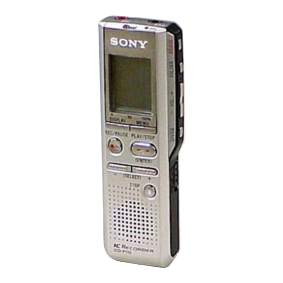
ICD-B200RS
SPECIFICATIONS
Recording media
Built-in flash memory 32MB,
Monaural recording
Recording time
HQ : 3 hours 40 minutes
SP : 9 hours 50 minutes
LP : 16 hours 10minutes
Frequency range
HQ
: 250 Hz – 6,800 Hz
SP/LP: 220 Hz – 3,400 Hz
Speaker
approx. 2.0 cm (
Power output
250 mW
Input/Output
• Earphone jack (minijack) for 8 – 300 ohms
ear receiver/headphones
• Microphone jack (minijack, monaural)
Plug in power
Minimum input level 0.6 mV
3 kilohms or lower impedance microphone
Power requirements
Two LR03 (size AAA) alkaline batteries: 3 V DC
Dimensions (w/h/d) (not incl. projecting parts and controls)
30.0 × 103.5 × 16.0 mm (1
Mass (incl. batteries)
58 g (2.1 oz)
Supplied accessories
Operating instructions (1)/Ear receiver
(MDR-E0110LP) (1)
Design and specifications are subject to change without
notice.
in.) dia.
13/16
× 4
×
in.)
3/16
1/8
21/32
US Model
IC RECORDER
1
Advertisement
Table of Contents

Related Manuals for Sony ICD-B200RS


Summary of Contents for Sony ICD-B200RS
- Page 1 Mass (incl. batteries) 58 g (2.1 oz) Supplied accessories Operating instructions (1)/Ear receiver (MDR-E0110LP) (1) Design and specifications are subject to change without notice. IC RECORDER Sony Corporation 9-879-655-01 Personal Audio Group 2005D04-1 Published by Sony Engineering Corporation © 2005.04...
-
Page 2: Table Of Contents
ICD-B200RS Notes on Chip Component Replacement TABLE OF CONTENTS • Never reuse a disconnected chip component. • Notice that the minus side of a tantalum capacitor may be GENERAL ..............3 damaged by heat. DISASSEMBLY UNLEADED SOLDER 2-1. Case (Front) Assy ............4 Boards requiring use of unleaded solder are printed with the lead 2-2. -
Page 3: General
ICD-B200RS SECTION 1 GENERAL This section is extracted from instruction manual. Index to Parts and Controls Main unit MIC jack (PLUG IN POWER) EAR (earphone) jack OPR (operation) indicator MIC (built-in microphone) ERASE Display window FOLDER MENU VOL (volume) +/–... -
Page 4: Disassembly
ICD-B200RS SECTION 2 DISASSEMBLY • This set can be disassembled in the order shown below. 2-1. CASE (FRONT) ASSY (Page 4) 2-2. SWITCH BOARD, MAIN BOARD (Page 5) 2-3. AUDIO BOARD (Page 5) Note: Follow the disassembly procedure in the numerical order given. -
Page 5: Switch Board, Main Board
ICD-B200RS 2-2. SWITCH BOARD, MAIN BOARD 2 SWITCH board 1 CN705 S701 4 MAIN board 3 CN701 2-3. AUDIO BOARD 3 screw 0 AUDIO board 4 speaker (2cm) S702 5 claw 7 claw 1 battery case lid 2 cushion (battery case lid) -
Page 6: Service Mode
ICD-B200RS SECTION 3 SERVICE MODE 3-1. Setting the Service Mode 3-3-2. FlashMemory ID display The ID of FlashMemory is displayed. This ID represents the To enter the service mode, use the following procedure: manufacturer code and device code. With the power on, turn the HOLD switch on while pressing the x STOP key and the VOLUME–... - Page 7 ICD-B200RS 3-3-4. LCD test 1) Segment test The initial screen for LCD test displays the blinking characters The segment test is intended to check whether Com-Seg Map is “LCD”. The LCD test mode includes seven different LCD tests. correct or not. When this test mode is selected, the initial screen The LCD test mode is executed by pressing the Bx key while the displays the blinking characters “SEG”.
- Page 8 ICD-B200RS 3-3-6. Battery value 2) MOJI test The MOJI test is intended to show the character display (characters/ The voltage value of the battery inserted into the set is displayed in digits). When this test mode is selected, the initial screen displays hexadecimal format.
- Page 9 ICD-B200RS 3-3-8. Reset menu The reset menu is used to initialize menu contents. When this mode is selected, the initial screen for reset menu displays the characters “RST MENU”. Pressing of Bx key during “RST MENU” character display will cause the menu information to be initialized.
-
Page 10: Diagrams
ICD-B200RS SECTION 4 DIAGRAMS • Waverforms THIS NOTE IS COMMON FOR PRINTED WIRING – AUDIO board – BOARDS AND SCHEMATIC DIAGRAMS. (In addition to this, the necessary note is printed in each block.) IC101 ta (XOUT) Common Note on Schematic Diagrams: •... -
Page 11: Block Diagram
ICD-B200RS 4-1. BLOCK DIAGRAM IC101 A/D,D/A CONVERTER, IC102 IC104 MIC101 MIC AMP SPEAKER AMP LOUT0 47 MIP J101 SPEAKER VCCA +3.3V (PLUG IN POWER) (VCC A) Q101 BYPASS MUTE +3.3V (VCC B) SENS Q102 25 27 58 24 54 S702... -
Page 12: Printed Wiring Board - Audio Section
ICD-B200RS 4-2. PRINTED WIRING BOARD — AUDIO SECTION — :Uses unleaded solder. AUDIO BOARD (SIDE A) • Semiconductor Location TP103 R128 Ref. No. Location Q501 L502 C509 D504 TP105 TP509 J103 IC104 (IC101) TP508 IC102 FB103 TP502 IC104 IC502 R139... -
Page 13: Schematic Diagram - Audio Section
ICD-B200RS 4-3. SCHEMATIC DIAGRAM — AUDIO SECTION — • See page 10 for Waveform. • See page 17 for IC Block Diagrams. IC B/D TP505 R134 RB102 RB103 IC104 C127 R128 TP105 TP101 C114 R125 MIC101 R118 TP103 R129 C111... -
Page 14: Printed Wiring Board - Main Section
ICD-B200RS 4-4. PRINTED WIRING BOARD — MAIN SECTION — :Uses unleaded solder. MAIN BOARD (SIDE B) • Semiconductor Location TP702 Q703 TP506 LCD701 Ref. No. Location C702 LIQUID CRYSTAL DISPLAY PANEL TP721 D701 R730 (D702) C715 R704 TP718 R731 R734... -
Page 15: Printed Wiring Board - Switch Section
ICD-B200RS 4-5. PRINTED WIRING BOARD — SWITCH SECTION — :Uses unleaded solder. SWITCH BOARD (SIDE A) S701 HOLD TP705 MAIN CN705 BOARD TP709 CN704 (Page 14) TP708 TP707 TP706 (21) 1-862-930- SWITCH BOARD (SIDE B) S707 S715 DISPLAY S705 z X REC/PAUSE... -
Page 16: Schematic Diagram - Main Section
ICD-B200RS 4-6. SCHEMATIC DIAGRAM — MAIN SECTION — • See page 10 for Waveforms. • See page 17 for IC Block Diagram. • See page 18 for IC Pin Function Description. TP506 IC704 R708 D702 R704 C702 X702 C703 C704... - Page 17 ICD-B200RS • IC Block Diagrams – AUDIO Board – IC104 MM3111AWLE IC102 NJM2781RB1 SHUTDOWN NOISE BIAS BYPASS STBY – MAIN Board – IC704 RS5C348A-E2-FB 32 kHz 32KOUT ALARM W REGISTER OUTPUT COMPARATOR (WEEK, MIN, HOUR) CONTROL ALARM D REGISTER COMPARATOR...
- Page 18 ICD-B200RS • IC Pin Function Description IC703 µPD780308GC-A77-8EU (MEMORY CONTROL, SYSTEM CONTROL) (MAIN BOARD) Pin No. Pin Name Description KEY1, KEY2 Key signal input DC-IN Not used. (Open) HOLD Hold switch signal input AMPPOW Power down control signal output to the power amplifier IC (IC104)
- Page 19 ICD-B200RS Pin No. Pin Name Description XDCINDET Not used. (Open) WAKEUP WAKE UP signal input RTCINT Real time clock (2 Hz) signal input FLMPOW Flash memory power ON/OFF signal output DSPIFACK I/F acknowledge signal input to the DSP IC (IC101)
-
Page 20: Exploded Views
ICD-B200RS SECTION 5 EXPLODED VIEWS NOTE: • -XX and -X mean standardized parts, so they • Items marked “*” are not stocked since they may have some difference from the original are seldom required for routine service. one. Some delay should be anticipated when •... -
Page 21: Case (Rear) Section
ICD-B200RS 5-2. CASE (REAR) SECTION Ref. No. Part No. Description Remark Ref. No. Part No. Description Remark 2-050-733-01 KNOB (HOLD) 2-050-741-02 TERMINAL (–), BATTERY 2-050-742-11 KNOB (MIC) 2-050-740-01 TERMINAL (+), BATTERY 2-050-737-02 BUTTON (SIDE) 3-254-014-01 SCREW 2-050-729-71 CASE (REAR) 2-050-731-41 BELT, ORNAMENTAL 2-050-739-02 TERMINAL (+.–), BATTERY... -
Page 22: Electrical Parts List
ICD-B200RS SECTION 6 AUDIO ELECTRICAL PARTS LIST NOTE: • Due to standardization, replacements in the • Items marked “*” are not stocked since they When indicating parts by reference number, parts list may be different from the parts are seldom required for routine service. - Page 23 ICD-B200RS AUDIO MAIN Ref. No. Part No. Description Remark Ref. No. Part No. Description Remark < RESISTOR > A-1084-532-A MAIN BOARD, COMPLETE ********************* R101 1-218-961-11 RES-CHIP 4.7K 1/16W R105 1-218-957-11 RES-CHIP 2.2K 1/16W 1-780-155-21 CONDUCTIVE BOARD, CONNECTION R106 1-218-990-11 SHORT CHIP...
- Page 24 ICD-B200RS MAIN SWITCH Ref. No. Part No. Description Remark Ref. No. Part No. Description Remark < RESISTOR > < RESISTOR > R701 1-218-985-11 RES-CHIP 470K 1/16W R748 1-218-953-11 RES-CHIP 1/16W R702 1-218-985-11 RES-CHIP 470K 1/16W R749 1-218-957-11 RES-CHIP 2.2K 1/16W...
- Page 25 ICD-B200RS MEMO...
- Page 26 ICD-B200RS REVISION HISTORY Clicking the version allows you to jump to the revised page. Also, clicking the version at the upper on the revised page allows you to jump to the next revised page. Ver. Date Description of Revision 2005. 04...