Table of Contents
Advertisement
Quick Links
Colour Television
Service Manual
Model CE25D5-C
Service Ref. No. CE25D5-C-00
PRODUCT CODE: 111351215
ORIGINAL VERSION: Chassis No. EB6-A
Give complete "SERVICE REF. NO." for parts
order or servicing, it is shown on the rating sheet
on the cabinet back of the TV set.
Note
This TV receiver will not work properly in foreign
countries where the television transmission
system and power source differ from the design
specifications. Refer to the specifications for the
design specifications
Contents
Safety precautions/Specifications . . . . . . . . . . . . . . . . . . . . . . . . . . . . . . . . . . . . . . . . . . . . . 2
Block diagrams . . . . . . . . . . . . . . . . . . . . . . . . . . . . . . . . . . . . . . . . . . . . . . . . . . . . . . . . . . . 3~5
Cabinet Disassembly . . . . . . . . . . . . . . . . . . . . . . . . . . . . . . . . . . . . . . . . . . . . . . . . . . . . . . 6
Adjustment and Repair Procedures. . . . . . . . . . . . . . . . . . . . . . . . . . . . . . . . . . . . . . . . . . . . 7~11
CPU Functions . . . . . . . . . . . . . . . . . . . . . . . . . . . . . . . . . . . . . . . . . . . . . . . . . . . . . . . . . . . . 12~13
Component Locations. . . . . . . . . . . . . . . . . . . . . . . . . . . . . . . . . . . . . . . . . . . . . . . . . . . . . . 14~15
IC Block Diagrams . . . . . . . . . . . . . . . . . . . . . . . . . . . . . . . . . . . . . . . . . . . . . . . . . . . . . . . . 16~20
Pin description of semiconductors. . . . . . . . . . . . . . . . . . . . . . . . . . . . . . . . . . . . . . . . . . . . . 21
Part Description and reading of schematic diagram. . . . . . . . . . . . . . . . . . . . . . . . . . . . . . . . 22
Cabinet Parts List . . . . . . . . . . . . . . . . . . . . . . . . . . . . . . . . . . . . . . . . . . . . . . . . . . . . . . . . . 23
Electric Parts List . . . . . . . . . . . . . . . . . . . . . . . . . . . . . . . . . . . . . . . . . . . . . . . . . . . . . . . . 24~31
Part No.
SKSM0381
CE25D5-C-01
CE25D5-C-02
C2VTV/VTS
25D5
CE
AUGUST 2000
-C
Advertisement
Table of Contents

Related Manuals for Sanyo CE25D5-C


Summary of Contents for Sanyo CE25D5-C
-
Page 1: Table Of Contents
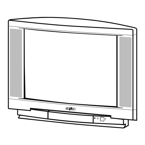
Colour Television 25D5 Service Manual Model CE25D5-C Service Ref. No. CE25D5-C-00 CE25D5-C-01 CE25D5-C-02 PRODUCT CODE: 111351215 ORIGINAL VERSION: Chassis No. EB6-A Give complete "SERVICE REF. NO." for parts order or servicing, it is shown on the rating sheet on the cabinet back of the TV set. -
Page 2: Safety Precautions/Specifications
SAFETY PRECAUTION 1: An isolation transformer should be connected in the 3: When replacing a chassis in the cabinet, always be power line between the receiver and the AC line certain that all the protective devices are installed when a service is performed on the primary of the properly, such as, control knobs, adjustment covers or converter transformer of the set. -
Page 3: Block Diagrams
BLOCK DIAGRAM This is a diagram for all models and therefore differs slightly from the actual block diagram. Outline C2VTV... - Page 4 AV Selector IC1201 NICAM DECODER AV-SELECTOR <MM1313> K12H Q1203 FRONT AV3 MONITOR-OUT FRONT-AV (V)34 1(V) 2(L) Q1202 MONITOR-OUT 4(R) Y-IN SC-1 SC-1 13(V) (VIDEO/AUDIO-L/R) 14(L) 16(R) SC-2 SC-2 IC3451 C-IN 7(V) (VIDEO/Y/C/AUDIO-L/R) 8(L) NICAM 9(Y) L-OUT & 10(R) 11(C) R-OUT STEREO K12J <TDA9875>...
- Page 5 Deflection Control IC501 V-Output<LA7846> Deflection Yoke Vert. V-Drive Coil IC201 IF/VIDEO/ Q431 DEFLECTION H-Output Horiz. T431 Q431 <TB1251> Drive Trans Coil H-Drive T451 FlyBack Trans D441 CS SW Screen Width Control EW-Out Pcc Control Q461 Q462 C2VTV...
-
Page 6: Cabinet Disassembly
CABINET DISASSEMBLY CABINET BACK DISASSEMBLY 1. Remove 7 screws(A). 2. Pull out the cabinet back. PLACING THE CHASSIS TO SERVICE POSITION 1. Pullout the chassis and put it to the rails on the side cabinet. 2. Fix main board with hook on the top rail. C2VTV... -
Page 7: Adjustment And Repair Procedures
OPTION SETTING [After replacing the Memory IC (IC803)] The memory IC, IC803, stores the option data of TV set and service adjustments data for each circuit, therefore, when the memory IC is replaced, it should be performed following setting and “SERVICE ADJUSTMENT” on next page. - Page 8 SERVICE ADJUSTMENTS Note: Some items of the service adjustments for this chassis are controlled by the CPU, IC801, and the adjustments are carried out by using the RC handset. [After replacing the Memory IC (IC803)] The memory IC, IC803, stores the service adjustments data for each circuit, therefore, when the memory IC is replaced, it should be performed “OPTION SETTING”...
- Page 9 To select the mode and service item and change data value + Highlight the desired adjustment mode by using the P or P button and then press the F/OK button. + To select the adjustment item, use the P or P button.
- Page 10 ADJUSTMENTS IMPORTANT NOTICE Do not attempt to adjust the following service adjustments except when adjustments are required in servicing otherwise it may cause loss of performance and product safety. DRIVE ADJUSTMENT + B VOLTAGE ADJUSTMENT 6. Select item no.3 “REGULAR 3, GRY” (G-Drive) or 4 “REGULAR 4, GRY”...
- Page 11 CORNER ADJUSTMENT 1. Receive cross hatch pattern and set screen mode to VERTICAL HEIGHT ADJUSTMENT “FULL”. 1. Receive circular pattern and set screen mode to 2. Enter to the service mode and select mode “WIDE”, “FULL”. and select item no. 10 “WIDE 10.P CNR”. 2.
-
Page 12: Cpu Functions
CPU PORT FUNCTIONS Pin No. Function Name Function IN/OUT MMU0 External memory 0 MMU3 External memory 3 ADDR10 Address bus 10 Data Strobe ADDR11 Address bus 11 ADDR9 Address bus 9 ADDR8 Address bus 8 Read Write Strobe Power Supply OSC-IN Clock Input OSC-OUT... - Page 13 Pin No. Function Name Function IN/OUT WSCF VPS/WSS Slicer Line PLL VDD-A Analogue Power Supply PXFM Pixel Frequency Multiplier RESET Reset Input (Active L) MCFM Pixel Frequency Multiplier JTRSTO TXCF CVBS0 TEST0 CVBS1 Video signal Input CVBS2 Video Signal Input GND-A DAT3 Data bus 3...
-
Page 14: Component Locations
COMPONENT LOCATIONS MAIN BOARD A101 T131 IC001 IC802 IC501 Q432 T611 -14- C2VTV... - Page 15 CRT BOARD Q701 C735 K7D1 -15- C2VTV...
-
Page 16: Ic Block Diagrams
IC BLOCK DIAGRAMS IC001 TDA7263M <Audio Output> CF COUPL RF1 27K IN -L OUT L IN +L MUTE PROTECTION REFERENCES TURN-ON SUPPLY AND-OFF PROTECTION VOLTAGE IN +R OUT R IN -R TDA7263M RF1 27K CF COUPL IC501 LA7846N <Vertical Output> THERMAL PUMP PROTECTION... - Page 17 IC201 TB1251AN <IF/Video/Chroma/Def.> H.AFC ABCL IN ref R FBP IN/SCP OUT H Vcc(9V) V OUT H OUT V NFB V RAMP Dig GND V BIAS FILTER B OUT BLACK Det G OUT Dig.VDD R OUT Sync in YC GND Y IN EXT.B IN DC Restor EXT.G IN...
- Page 18 IC1301 LA6393D <Operation Amplifier> IC1303 M34225M1<Single Chip Micro-computer> -18- C2VTV...
- Page 19 IC1201 MM1313BD<AV Selector> IC3451 TDA9875A <NICAM & Stereo Sound Decoder> AUXOR SIF1 AUXOL SIF2 -19- C2VTV...
- Page 20 IC3001 FA5311P <Power Switching Controller> BIAS UVLO FA5311P IC3051 TA8216H <Audio Amplifier> TA8216H AMP2 AMP1 SPEAKER SPEAKER -20- C2VTV...
-
Page 21: Pin Description Of Semiconductors
PIN DESCRIPTION OF SEMICONDUCTORS Diode Diode K: Cathode A: Anode Transistor/FET Transistor/FET C: Collector D: Drain B: Base G: Gate Index E: Emitter S: Source C1 C2 C1 C2 (GND) RESET (IN) (OUT) Index Index Index Index Index Index Index Index Index -21-... -
Page 22: Part Description And Reading Of Schematic Diagram
PARTS DESCRIPTION AND READING IN SCHEMATIC DIAGRAM 1. The parts specification of resistors, capacitors and Resistor Reading coils are expressed in designated code. Please Example 1/2 D J 10K B check the parts description by the following code table. Characteristic 2. -
Page 23: Cabinet Parts List
CABINET PARTS LIST FOR MODEL CE25D5-C-00/01/02 Note: Parts order must contain Service Ref. No., Part No., and descriptions. Ref. No. Part No. Description Ref. No. Part No. Description 411 076 1301 SCR TPG BRZ 4X14 CABINET PARTS 610 286 7596... -
Page 24: Electric Parts List
Note: Parts order must contain Service Ref. No., Part No., and descriptions. Description Part No. Ref. No. Chassis construction CE25D5-C-00 1AA0B10H04200 ASSY,PWB,MAIN C2VTV (Page 24~30) 1AA0B10E62700 ASSY,PWB,TEXT V C2HC (Page 29) - Page 25 Description Ref. No. Part No. Description Ref. No. Part No. C1027 403 233 0817 ELECT 10U M C247 403 233 0817 ELECT 10U M C1028 403 113 3815 CERAMIC 1000P K C251 403 314 5915 SMD CAP GRM40X7R474K16 C1029 403 233 0817 ELECT 10U M C252 403 314 5915...
- Page 26 Ref. No. Description Ref. No. Part No. Description Part No. C824 403 153 9310 CERAMIC 82P J D683 407 005 7328 DIODE EM01Z C826 403 086 1808 NP-ELECT 0.47U M D684 408 007 8607 DIODE 1N4148 C827 403 314 5915 SMD CAP GRM40X7R474K16 D685 407 012 4416 DIODE 1SS133-T-77...
- Page 27 Ref. No. Part No. Description Part No. Ref. No. Description Q1002 405 002 0318 TR 2SA1037K-T96-R R1014 401 105 5915 MT-GLAZE 560 JA 1/16W Q1003 405 014 4519 TR 2SC2412KT146/R R1015 401 105 5915 MT-GLAZE 560 JA 1/16W Q1006 405 002 0318 TR 2SA1037K-T96-R R1016 401 026 7428 CARBON 39K JA...
- Page 28 Part No. Ref. No. Part No. Ref. No. Description Description R215 401 105 0415 MT-GLAZE 100 JA 1/16W R621 401 007 5815 CARBON 120K JA 1/2W R216 401 105 0613 MT-GLAZE 10K JA 1/16W R622 401 014 5241 CARBON 15K JA 1/4W R217 401 024 7430 CARBON...
- Page 29 Ref. No. Description Ref. No. Part No. Part No. Description R857 401 105 4215 MT-GLAZE 33K JA 1/16W KEM1 645 008 4058 TERMINAL PLUG R858 401 026 3925 CARBON 330 JA 1/6W KF-1 645 008 4058 TERMINAL PLUG R859 401 105 5915 MT-GLAZE 560 JA 1/16W KF-2 645 008 4058 TERMINAL PLUG...
- Page 30 Ref. No. Description Ref. No. Part No. Part No. Description C1202 403 248 1618 ELECT 47U M C1204 403 233 1111 ELECT 22U M COIL C1205 403 298 9619 CERAMIC 0.1U K L1201 645 008 2467 PEAKING COIL C1206 403 298 9619 CERAMIC 0.1U K L1202...
- Page 31 Part No. Description Ref. No. Ref. No. Part No. Description R3473 401 105 5212 MT-GLAZE 470 JA 1/16W DIODE R3474 401 105 2815 MT-GLAZE 2.2K JA 1/16W D701 407 012 4416 DIODE 1SS133-T-77 R3475 401 105 5212 MT-GLAZE 470 JA 1/16W D711 407 012 4416 DIODE 1SS133-T-77...
- Page 32 1/6W CE25D5-C-01 J213 401 024 6720 CARBON 100 JA 1/6W J500 DELETED Q803 DELETED R-RNBOURN1025 RESISTOR NETWORK ALL PANELS ARE THE SAME AS CE25D5-C-00 R847 DELETED EXCEPT FOR THE FOLLOWING DIFFERENCES R848 DELETED R849 DELETED ASSY,PWB,MAIN C2VTS 1AA0B10H042J0 R850 DELETED SAME AS “ASSY,PWB,MAIN C2VTV 1AA0B10H04200”...