Table of Contents
Advertisement
RPIH-3.0HNAUN1Q
RPIH-3.3HNAUN1Q
RPIH-4.0HNAUN1Q
RPIH-5.0HNAUN1Q
RPIH-6.0HNAUN1Q
RPIM-0.8HNAUN1Q
Ceiling Ducted
RPIM-1.0HNAUN1Q
Type
RPIM-1.3HNAUN1Q
RPIM-1.5HNAUN1Q
RPIM-1.8HNAUN1Q
RPIM-2.0HNAUN1Q
RPIM-2.3HNAUN1Q
RPIM-2.5HNAUN1Q
RPIL-0.8HNAUN1Q
This manual is exclusively prepared for
R410A indoor unit. Please read this manual
in conjunction with corresponding manual for
outdoor unit.
RPIL-1.0HNAUN1Q
RPIL-1.3HNAUN1Q
RPIL-1.5HNAUN1Q
RPIL-1.8HNAUN1Q
RPIL-2.0HNAUN1Q
RPIL-2.3HNAUN1Q
RPIL-2.5HNAUN1Q
RPIL-3.0HNAUN1Q
RPIL-3.3HNAUN1Q
RPIL-4.0HNAUN1Q
RPIL-5.0HNAUN1Q
RPIL-6.0HNAUN1Q
P01973Q
ORIGINAL INSTRUCTIONS
Advertisement
Table of Contents

Related Manuals for Hitachi RPIH-3.0HNAUN1Q


Summary of Contents for Hitachi RPIH-3.0HNAUN1Q
- Page 1 RPIH-3.0HNAUN1Q RPIL-1.0HNAUN1Q RPIH-3.3HNAUN1Q RPIL-1.3HNAUN1Q RPIH-4.0HNAUN1Q RPIL-1.5HNAUN1Q RPIH-5.0HNAUN1Q RPIL-1.8HNAUN1Q RPIH-6.0HNAUN1Q RPIL-2.0HNAUN1Q RPIM-0.8HNAUN1Q RPIL-2.3HNAUN1Q Ceiling Ducted RPIM-1.0HNAUN1Q RPIL-2.5HNAUN1Q Type RPIM-1.3HNAUN1Q RPIL-3.0HNAUN1Q RPIM-1.5HNAUN1Q RPIL-3.3HNAUN1Q RPIM-1.8HNAUN1Q RPIL-4.0HNAUN1Q RPIM-2.0HNAUN1Q RPIL-5.0HNAUN1Q RPIM-2.3HNAUN1Q RPIL-6.0HNAUN1Q RPIM-2.5HNAUN1Q RPIL-0.8HNAUN1Q This manual is exclusively prepared for R410A indoor unit. Please read this manual in conjunction with corresponding manual for outdoor unit.
- Page 2 This declaration becomes invalid, if technical or operational modifications are introduced without the manufacturer's consent. Johnson Controls Hitachi Air Conditioning Europe SAS is authorized to compile technical file or relevant technical documentation. Address : Rue de Lombardie, Parc Aktiland II – 69800 Saint Priest, France...
-
Page 3: Important Notice
This manual should be considered as a permanent part of the air conditioning equipment. Please keep it properly. ● Hitachi pursues a policy of continuous improvement in design and performance of products. The right is therefore reserved ● to change specifications without notice. -
Page 4: Checking Product Received
WARNING Do not use any sprays such as insecticide, lacquer, hair spray or other flammable gases within approximately one (1) ● meter from the system. ● If the earth leakage breaker (ELB) is frequently activated, please stop the system and contact your local dealer or customer services. -
Page 5: Correct Disposal Of This Product
IMPORTANT NOTICE Correct Disposal of this product This marking indicates that this product should not be disposed with other household wastes. To prevent possible harm to the environment or human health from uncontrolled waste disposal, recycle it responsibly to promote the sustainable reuse of material resources. - Page 6 Unit Description Part Name 3.1 Indoor Unit 3.2 Remote Control Before Operation Operation Mode Auto Control Cleaning of Filter 7.1 Removing Filter 7.2 Cleaning Filter 7.3 Resetting Filter Indicator 8.1 If Trouble Still Remains 8.2 No Operation 8.3 Not Cooling or Heating Well 8.4 This is Not Abnormal...
- Page 7 Section 2 Installation & Maintenance Manual Wiring for Static Pressure Protection and Control Devices Field Operation...
-
Page 8: Unit Description
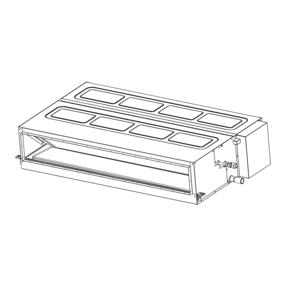
Unit Description This heat-pump type air conditioning unit can consist of one outdoor unit and several indoor units. Detailed Do not have the indoor unit or outdoor unit configurations are stated in the corresponding exposed to water. All these parts are designed installation &... - Page 9 Models: 0.8~2.5 Models: 3.0~6.0 Fig. 3.1 Ceiling Ducted Indoor Unit...
-
Page 10: Automatic Defrosting
4. Before Operation Freeze Protection during Refrigeration When the outlet air temperature of indoor unit is excessively low, refrigeration may be automatically switched to air supply mode, in which the unit runs for The units that have been left unused for a long period of a period of time to avoid frosting on indoor heat time shall be electrified for more than 12 hours before exchanger. -
Page 11: Cleaning Of Filter
7. Cleaning of Filter The operation of indoor unit is strictly prohibited without filter. Please turn off the main power supply before removing the filter (the previous operational function may occur). 8.1 If Trouble Still Remains 7.1 Removing Filter If the trouble still remains even after checking the following, contact your contractor and inform 7.2 Cleaning Filter them of the following items. - Page 12 Check whether the design pressure of machine is 4.15 MPa. The following tools are necessary for the installation & construction. Tool Tool Spanner Handsaw Charging Cylinder Phillips Screwdriver Gauge Manifold Vacuum Pump Cutter for Wires Refrigerant Gas Hose Megohmmeter Gas Leak Detector Copper Pipe Bender Leveller Water Pump...
- Page 13 Install the indoor unit as per national standard. possible Please contact the dealer if the accessories are not delivered with machine.
- Page 14 Models: 0.8~2.5 Unit: mm Electric Box Service Access (≥450) Back Front Install suspension bolts as shown in Fig. 4.2. Top View Models: 3.0~6.0 Unit: mm Electric Box For Concrete Slab For Steel Beam Service Access (≥450) Insert 1. When the ceiling is 150 to 160mm (100 to150kg) not removable, please...
- Page 15 4.3.2 Suspension Bolt and Pipe 4.3.3 Installation of Indoor Unit Connection Points Indoor unit is installed as shown in Fig. 4.4. Installation of Field-Supplied Parts (1) Indicate the location of suspension bolt, and the connection points of refrigerant pipe and drain Suspension Bolt 4-M10 or W3/8 pipe.
-
Page 16: Air Duct Connection
4.3.5 Air Duct Connection (2) Installation of Indoor Unit Air duct is connected to indoor unit via canvas hose Place the left bracket on the nut and washer of to effectively isolate noise and vibration. Indoor unit suspension bolt as shown in the figure below. is designed with flange with hole connectible to air Make sure the left bracket is properly placed duct. -
Page 17: Piping Connection
As shown in Fig. 5.4, two spanners shall be used for 5.2 Piping Connection tightening the nut. (1) Piping connection points are shown in Figs. 5.1 and 5.2. Models 0.8~2.5 Drain Pipe Refrigerant Gas Tube For Drain Pump Refrigerant Liquid Tube (mm) (N.m) Drain Pipe... -
Page 18: Drain Pipe
Where the relative humidity of air inlet or Excessive and inadequate refrigerant is a ambient air exceeds 80%, an auxiliary drain pan leading cause of system anomaly. Please shall be fabricated at installation site and placed inject the right amount of refrigerant. under the indoor unit, as shown in Fig. - Page 19 Check the capacity of power source. The system can't be started if the supply ● voltage is excessively low. Turn OFF the main power switch to the indoor unit and the outdoor unit and wait for at least 10 minutes before electrical wiring work or a periodical check is performed.
- Page 20 7.3 Static Pressure Selection Wiring this Static Pressure (Pa) RPIM-0.8~2.5HNAUN1Q Plug Wording Static Pressure (Pa) RPIH-3.0~6.0HNAUN1Q Plug Wording *: Factory default The plug printed with number "1" before delivery of above-noted indoor unit is inserted into the socket. To change the static pressure, insert the plug printed with number "2".
-
Page 21: Field Operation
10. Field Operation 10.1 Field Minimum Wire Size for Power Source Line Diameters of Field-Connected Wires and Power Cords Power Cord Signal Wire Power Supply Rated Current Models Specifications Specifications RPIL-0.8~1.0HNAUN1Q 0.49A RPIL-1.3~1.5HNAUN1Q 0.90A 0.76A RPIL-1.8~2.0HNAUN1Q 220-240V ~ 50Hz 1.38A RPIL-2.3~2.5HNAUN1Q 2.04A RPIL-3.0~4.0HNAUN1Q... - Page 22 Safety reset (DSW7) No setup is needed All are set to OFF before delivery. (A) Positions of DIP Switches * In the case of applying high voltage to terminals 1 and 2 of TB2, the fuse on the PCB, is cut. In such a case, firstly connect the wiring to TB2, and then turn on NO.1 pin.
- Page 24 1154113 Qingdao Hisense Hitachi Air-conditioning Systems Co., Ltd. Add.: No. 218, Qianwangang Road, Economic and Technological Development Zone, Qingdao, China The Company is committed to continuous product improvement. We reserve the right, therefore, to alter the product information at any time and without prior announcement.