
Related Manuals for GE DPS 5000 Series


Summary of Contents for GE DPS 5000 Series
- Page 1 Measurement & Control DPS 5000 Series Sensors C-bus Pressure Transducer User Manual – K0582 English...
- Page 2 Druck Ltd., Fir Tree Lane, Groby. Leicester, LE6 0FH, UK. Tel: +44 (0)116 231 7100; Fax +44 (0)116 231 7103 © 2015 General Electric Company. All rights reserved...
- Page 3 For further details refer to the Sales Data Sheet or the customer specification drawing. A full conformity certificate is available from the manufacturer. Contact GE Measurement & Control www.gemeasurement.com The EMC directive is only applicable to the external variant (model E503D)
- Page 4 Abbreviations The following abbreviations are used in this manual. Note: Abbreviations are the same in the singular and plural Analogue to digital converter Addr Address ASCII American standard code for information interchange atmosphere Electro-static discharge Feet of water HectoPascal Hertz Inter-integrated circuit IEEE Institute of Electrical and Electronic Engineers...
- Page 5 References Reference 1 C-bus specification and user manual, NPX Semiconductor UM10204 Rev. 6 available from www.nxp.com K0582 Revision B May 2015...
-
Page 6: Table Of Contents
Contents Introduction General Configuration Installation General Mounting and orientation Connecting to the pressure source Electrical connections Functional description Sensor communication Memory map Register descriptions 3.3.1 Register bit table legend 3.3.2 Address 0 - STATUS 3.3.3 Address 1 – COMP_PRES 3.3.4 Address 2 –... - Page 7 Operational description Operational states Reading the pressure and temperature Updating the pressure and temperature 4.3.1 Manual update 4.3.2 Automatic update Updating the sensor configuration data registers 4.4.1 User modifiable registers 4.4.2 Modifying the I C-bus address 4.4.3 Changing the auto-update period 4.4.4 Changing the unit of pressure 4.4.5...
- Page 8 Page left intentionally blank May 2015 K0582 Revision B...
-
Page 9: Introduction
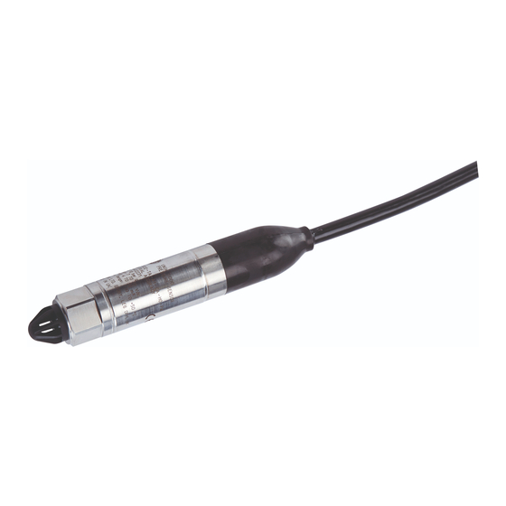
Figure 1 External and internal DPS 5000 sensors – General view The DPS 5000 series sensors are low powered devices offering a high level of accuracy over a wide temperature range. The I... -
Page 10: Installation
Mounting and orientation The DPS 5000 series sensors are designed to be mounted in any orientation. However, the sensor is a harsh media isolated product and the isolation is achieved by hermetically sealing the sensor chip within an oil filled chamber. The weight of the oil gives a g-sensitivity as a pressure offset error that may be noticeable at the lowest pressure ranges. -
Page 11: Electrical Connections
Figure 2 Pressure connection Torque tighten the sensor in accordance with the system installation manual. Electrical connections The DPS 5000 series sensors employ a 4 wire I C-bus user electrical interface: Supply + Serial data (SDA) Serial clock (SCL) Supply –... -
Page 12: Functional Description
Each slave device on an I C-bus network must have a unique address. The default address for the DPS 5000 series sensors is 2, but may be changed over the bus as required to any value within the range 1 to 127. -
Page 13: Memory Map
addressed register. As the sensor registers are 32 bits wide, the read and write transfers are generally 4 bytes long. However, 1, 2 or 3 byte transfers are allowed. Memory map The DPS 5000 sensor registers are mapped within a 1 kbyte memory space. As each register is 4 bytes wide, the register addresses range from 0 to 255. -
Page 14: Address 0 - Status
Figure 5 Bit table legend Not all bits within a register are available to the user. Reserved bits always read as 0b0 and writes have no effect. Unused bits are readable and writable but have no effect on the sensor operation. 3.3.2 Address 0 - STATUS Bit 31... -
Page 15: Address 1 - Comp_Pres
No error Error Bit 9 INTRDG: Read/write – used to enable the sensor interleave mode. ADC_ON (bit 4) is always set when enabled, and alternate pressure and temperature ADC values are used to generate the updated pressure and temperature readings. Disabled Enabled Bit 8... -
Page 16: Address 2 - Comp_Temp
Bit 15 Bit 14 Bit 13 Bit 12 Bit 11 Bit 10 Bit 9 Bit 8 COMP_PRES [15..8] Bit 7 Bit 6 Bit 5 Bit 4 Bit 3 Bit 2 Bit 1 Bit 0 COMP_PRES [7..0] Bit 31–0 COMP_PRES [31..0]: Read only – the most recently updated compensated pressure value in the pressure units defined by the PRES_UNIT register (address 84). -
Page 17: Address 4 - Adc_Temp
3.3.6 Address 4 – ADC_TEMP Bit 31 Bit 30 Bit 29 Bit 28 Bit 27 Bit 26 Bit 25 Bit 24 ADC_TEMP [31..24] Bit 23 Bit 22 Bit 21 Bit 20 Bit 19 Bit 18 Bit 17 Bit 16 ADC_TEMP [23..16] Bit 15 Bit 14 Bit 13... -
Page 18: Address 7 - Mvolt_Temp
Bit 31–0 MVOLT _PRES [31..0]: Read only – the most recently updated pressure sensing element output voltage. This value is used in conjunction with the pressure and temperature coefficient registers to calculate the values held in the COMP_PRES and COMP_TEMP registers (addresses 1 and 2). Reading this register whilst the sensor is in the auto-update mode will clear the CONV (bit 0) flag of the STATUS register (address 0). -
Page 19: Address 67 - Coef_Fit
Valid address Valid address- default value ⁞ ⁞ Valid address Invalid address ⁞ ⁞ Invalid address 3.3.11 Address 67 – COEF_FIT Bit 31 Bit 30 Bit 29 Bit 28 Bit 27 Bit 26 Bit 25 Bit 24 TT_FIT(7..0] Bit 23 Bit 22 Bit 21 Bit 20... -
Page 20: Address 69 - Offset_Adj
Bit 31–0 GAIN_ADJ [31..0]: Read/write – the value of this register is used to modify the value of the COMP_PRES register (address 1). It is used in conjunction with the OFFSET_ADJ register (address 69) during user re-calibration of the sensor. 0xn..n Number type float Default value... -
Page 21: Address 72 - Cal_Date
Bit 15 Bit 14 Bit 13 Bit 12 Bit 11 Bit 10 Bit 9 Bit 8 MIN_RANGE [15..8] Bit 7 Bit 6 Bit 5 Bit 4 Bit 3 Bit 2 Bit 1 Bit 0 MIN_RANGE [7..0] Bit 31–0 MIN_RANGE [31..0]: Read only – the lower limit of the sensor pressure range in the pressure units defined by the PRES_UNIT register (address 84). -
Page 22: Address 74 - Min_Adc_Pres
Bit 31–0 MAX_ADC_PRES [31..0]: Read only – if the current value of the ADC_PRES register (address 3) exceeds this value, VALID[0] (bit 1) of the STATUS register (address 0) will be cleared. 0xn..n Number type unsigned word 3.3.18 Address 74 – MIN_ADC_PRES Bit 31 Bit 30 Bit 29... -
Page 23: Address 77 - Serial
Bit 7 Bit 6 Bit 5 Bit 4 Bit 3 Bit 2 Bit 1 Bit 0 MIN _ADC_TEMP [7..0] Bit 31–0 MIN_ADC_TEMP [31..0]: Read only – if the current value of the ADC_TEMP register (address 4) is less than this value, VALID[1] (bit 2) of the STATUS register (address 0) will be cleared. -
Page 24: Address 79 - Version
0xn..n Number type extended ASCII Absolute Differential Gauge 3.3.23 Address 79 – VERSION Bit 31 Bit 30 Bit 29 Bit 28 Bit 27 Bit 26 Bit 25 Bit 24 FIELD_1 [31..24] Bit 23 Bit 22 Bit 21 Bit 20 Bit 19 Bit 18 Bit 17 Bit 16... -
Page 25: Address 83 - Pres_Conv
Invalid value ⁞ ⁞ Invalid value Bit 7–0 T_AVE[7..0]: Read/write – defines the number of individual temperature ADC data samples averaged to produce each pressure and temperature reading. 0xn..n Number type unsigned byte 1 sample 2 samples 4 samples ⁞ ⁞... -
Page 26: Address 85 - Delay
Bit 31–8 Unused, read/write Bit 7–0 PRES_UNIT[7..0]: Read/write – defines the manufacturer’s pressure unit for the values in the COMP_PRES, MAX_RANGE and MIN_RANGE registers (addresses 1, 70 and 71). May be updated to define the user pressure units created using the PRES_CONV register (address 83). -
Page 27: Address 86 - Spec_Dwg
3.3.28 Address 86 - SPEC_DWG Bit 31 Bit 30 Bit 29 Bit 28 Bit 27 Bit 26 Bit 25 Bit 24 SPEC_DWG [31..24] Bit 23 Bit 22 Bit 21 Bit 20 Bit 19 Bit 18 Bit 17 Bit 16 SPEC_DWG [23..16] Bit 15 Bit 14 Bit 13... -
Page 28: Addresses 158-187 - Temperature Coefficients
Bit 7 Bit 6 Bit 5 Bit 4 Bit 3 Bit 2 Bit 1 Bit 0 [7..0] P(IJ) R/W-X Bit 31–0 [31..0]: Read only P(IJ) 0xn..n Number type float 3.3.31 Addresses 158-187 - Temperature coefficients The temperature coefficient registers contain a total of (I+1)*(J+1) contiguous temperature coefficients where I and J represent the values of the TP_FIT(7..0] and TT_FIT[7..0] bits of the COEF_DIM register (address 67). -
Page 29: Reading The Pressure And Temperature
The sensor power is cycled and the sensor returns to the power-up state. User interaction results in a new data request being internally generated and the sensor re-enters the acquire state. CAUTION Due to the low power consumption of the DPS 5000 sensors, the I C-bus pull-up resistors may provide sufficient power to maintain the sensor in the standby state when the I... -
Page 30: Automatic Update
Initiate a data update. Write 0b1 to STATUS: CONV <0 [0]> Writing 0b1 to STATUS: CONV automatically clears the new data available flag. It is set back to 0b1 when the updated data is available which can then be read using the steps given in section 4.2. -
Page 31: Modifying The I 2 C-Bus Address
Check the configuration data write access status (optional). Read STATUS: WENB <0 [3]> 0b1 = configuration data write enabled The configuration registers may then be modified by writing the new user values to the appropriate registers. If the new user values are to be permanent, the following step must be performed: iii. -
Page 32: Changing The Unit Of Pressure
Re-enter the automatic update mode (if applicable). Write 0b1 to STATUS: AUTO <0 [8]> CAUTION The automatic update period should be chosen with care to avoid new updates being requested before the data from the preceding request is available. The update interval should be set to be longer than the sensor acquisition time (see section 4.4.6). -
Page 33: Pressure And Temperature Snr
For example, to set the pressure offset to 1.000000: Unlock the configuration data registers as described in section 4.4.1. Update the pressure offset value. Write 1.000000 to TARE_VALUE: TARE_VALUE [31..0] <87 [31..0]> iii. Save the new pressure offset value to non-volatile memory if required and re- lock the configuration data registers as described in section 4.4.1. -
Page 34: Maximising The Update Rate
For example, if the sensor has P_AVE[7..0] set to 2 and T_AVE[7..0] set to 1 and it is required to reduce the RMS amplitude of the pressure reading noise by a factor of 4 and the temperature reading noise by a factor of 2, then using Figure 8, the new values for P_AVE[7..0] and T_AVE[7..0] will be 6 and 3 respectively. -
Page 35: Maintenance
Apply a second known pressure, P , ideally ≥ 90% of the sensor’s full scale pressure, and record the measured pressure, P M2 12 = Read COMP_PRES: COMP_PRES [31..0] <1 [31..0]> iii. Read and record the current values G, O and C of the following configuration data registers: G = Read GAIN_ADJ: GAIN_ADJ [31..0] <68 [31..0]>... -
Page 36: Adjustment
±0.01% of reading. Note: GE can provide a calibration service that is traceable to international standards. Repair The DPS 5000 sensors contain no user serviceable items. For any repairs, return the sensor to the manufacturer or an approved service agent.