
Related Manuals for Bosch rexroth ctrlX DRIVE


Summary of Contents for Bosch rexroth ctrlX DRIVE
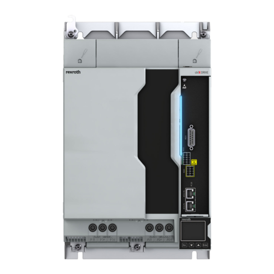
- Page 1 ctrlX DRIVE Drive Controllers, Supply Units Instruction Manual Edition 02 R911392530...
- Page 2 Copyright © Bosch Rexroth AG 2021 All rights reserved, also regarding any disposal, exploitation, reproduction, editing, distribution, as well as in the event of applications for industrial prop‐...
-
Page 3: Table Of Contents
Overall connection diagram XMD*-W5454…W7070................. 32 4.2.11 Overall connection diagram XMQ*-WQ001..................33 4.2.12 Overall connection diagram XMQ*-WQ002..................34 4.2.13 Overall connection diagram XVR...................... 35 4.2.14 Symbols (connection diagram)......................36 4.2.15 Connection points..........................37 Service and support..................... 39 Index..........................41 R911392530_Edition 02 Bosch Rexroth AG... - Page 4 DRIVE Drive Controllers, Supply Units Bosch Rexroth AG R911392530_Edition 02...
-
Page 5: Important Notes
Improper use of these components, failure to follow the safety instructions in this document or tampering with the product, including disabling of safety de‐ vices, could result in property damage, injury, electric shock or even death. R911392530_Edition 02 Bosch Rexroth AG... -
Page 6: Protection Against Contact With Electrical Parts And Housings
High housing voltage and high leakage current! Danger to life, risk of injury by electric shock! ● Before switching on and before commissioning, ground or connect the components of the electric drive and control system to the equipment grounding conductor at the grounding points. Bosch Rexroth AG R911392530_Edition 02... -
Page 7: Battery Safety
Do not throw batteries into open flames. ● Do not dismantle batteries. ● When replacing the battery/batteries, do not damage the electrical parts installed in the devices. ● Only use the battery types specified for the product. R911392530_Edition 02 Bosch Rexroth AG... -
Page 8: Intended Use
These components are not provided for use in a public low-volt‐ age mains supplying residential areas. If these components are used in such a mains, high-frequency interference is to be expec‐ ted. This can require additional measures of interference suppres‐ sion. Bosch Rexroth AG R911392530_Edition 02... -
Page 9: Ratings And Dimensions
× F DC_cont_red DC_cont x (1 - [(50 - 40) x 0.02]) = P x 0.8 °C 40 … 55 DC_cont DC_cont a_work_red Operation at ambient temperatures outside of and T is not allowed! a_work a_work_red R911392530_Edition 02 Bosch Rexroth AG... - Page 10 DC bus connection available at the device; without connector at the device, phases not connected (e.g., 1-phase mains connection) or without touch guard of DC bus connection at the device: IP10 Bosch Rexroth AG R911392530_Edition 02...
- Page 11 DRIVE Drive Controllers, Supply Units 7/43 Ratings and dimensions Resistance to hydrogen sulfide H S tested according to ANSI/ ISA‑71.04 (Class G3) for 10 years Tab. 2-1: Ambient and operating conditions R911392530_Edition 02 Bosch Rexroth AG...
-
Page 12: Drive Controllers
(U LN AC 400V Output frequency range 0 … 1600 1) 2) 3) Housing dimensions 4) 5) 6) See fig. "Air intake and air outlet at device" Comply with supply voltage for motor holding brake; Bosch Rexroth AG R911392530_Edition 02... - Page 13 1.5 (for devices of the ctrlX DRIVE product group outside of the Horizontal spacing at the device DC bus group (individual supply)) 10 (for everything else (control cabinet wall, other devices, etc.)) Rated control voltage input Rated control current input R911392530_Edition 02 Bosch Rexroth AG...
- Page 14 Copper wire; PVC-insulation (conductor temperature 75 °C; ≤ 40 °C) in accordance with NFPA 79 chapter 12 and UL 508A chapter 28 Depending on switching frequency which was set in parameter P‑0‑0001 Tab. 2-3: UL ratings and dimensions Bosch Rexroth AG R911392530_Edition 02...
- Page 15 CSA/UL: ● UL508-certified ● output voltage: DC 24V ● output current: ≤ 31 A; for power supply units with output current > 31 A: install fuses in accordance with UL248 See information on "Rated power consumption control voltage input at U " R911392530_Edition 02 Bosch Rexroth AG...
- Page 16 DC 254 ... 750 Rated input voltage, power LN_nom Rated input current DC 73 DC 77 29.4 38.2 49.1 Field wiring material (material; Cu; 60/75 °C; 1 conductor temperature; class) Output voltage AC 0 … 500 Bosch Rexroth AG R911392530_Edition 02...
- Page 17 (central supply)) 1.5 (for devices of the ctrlX DRIVE product group outside of the Horizontal spacing at the device DC bus group (individual supply)) 10 (for everything else (control cabinet wall, other devices, etc.)) R911392530_Edition 02 Bosch Rexroth AG...
- Page 18 Listing in accordance with UL UL 61800-5-1 standard Listing in accordance with CSA C22.2 No. 274-17 standard UL‑Files E134201 Pollution degree Ambient temperature range with °C amax nominal data Mass Device height Device depth 196.5 Device width Bosch Rexroth AG R911392530_Edition 02...
- Page 19 Copper wire; PVC-insulation (conductor temperature 75 °C; ≤ 40 °C) in accordance with NFPA 79 chapter 12 and UL 508A chapter 28 Depending on switching frequency which was set in parameter P‑0‑0001 Tab. 2-7: UL ratings and dimensions R911392530_Edition 02 Bosch Rexroth AG...
- Page 20 3 mm (2 × 1.5 mm) Distance top Distance bottom Distance horizontal Fig. 2-1: Air intake and air outlet at device Bosch Rexroth AG R911392530_Edition 02...
-
Page 21: Supply Units
Class J Fuse 200A Branch circuit protection fuse Required wire size in accordance with UL 508 A (internal wiring); Field wiring material (material; Cu; 75 °C; 1 conductor temperature; class) Output voltage DC 0 … 750 Output current R911392530_Edition 02 Bosch Rexroth AG... - Page 22 3 mm (2 × 1.5 mm) Distance top Distance bottom Distance horizontal Fig. 2-2: Air intake and air outlet at device Bosch Rexroth AG R911392530_Edition 02...
-
Page 23: China Rohs 2
DRIVE Drive Controllers, Supply Units 19/43 Ratings and dimensions China RoHS 2 www.boschrexroth.com.cn/zh/cn/home_2/china_rohs2 R911392530_Edition 02 Bosch Rexroth AG... - Page 24 20/43 ctrlX DRIVE Drive Controllers, Supply Units Bosch Rexroth AG R911392530_Edition 02...
-
Page 25: Overview Of Documentations
Ironless Linear Motors MCL In the documentation typecodes, "xx" is a placeholder for the current edition of the documentation (e.g.: PR01 is the first edi‐ tion of a Project Planning Manual) Tab. 3-1: Documentations – motors R911392530_Edition 02 Bosch Rexroth AG... - Page 26 22/43 ctrlX DRIVE Drive Controllers, Supply Units Bosch Rexroth AG R911392530_Edition 02...
-
Page 27: Instructions For Use
For Rexroth motors with data memory in the motor encoder, such as MSK, the motor overload protection level is set automatically while connecting the motor to the drive. There is no adjustment necessary. Otherwise refer to the Rexroth firmware documentation. R911392530_Edition 02 Bosch Rexroth AG... -
Page 28: Overall Connection Diagram Xcs*-W0054
Motor temperature monitoring and motor holding brake XG20 Digital encoder XG21 Multi-encoder (optional) XG31 Digital inputs/outputs; analog input XG4x Safety technology Fig. 4-1: Overall connection diagram XCS*-W0054…W0070 Symbols: See chapter 4.2.14 "Symbols (connection diagram)" on page 36 Bosch Rexroth AG R911392530_Edition 02... -
Page 29: Overall Connection Diagram Xcs*-W01Xx
Motor temperature monitoring and motor holding brake XG20 Digital encoder XG21 Multi-encoder (optional) XG31 Digital inputs/outputs; analog input XG4x Safety technology Fig. 4-2: Overall connection diagram XCS*-W01xx Symbols: See chapter 4.2.14 "Symbols (connection diagram)" on page 36 R911392530_Edition 02 Bosch Rexroth AG... -
Page 30: Overall Connection Diagram Xcs*-W02Xx
Motor temperature monitoring and motor holding brake XG20 Digital encoder XG21 Multi-encoder (optional) XG31 Digital inputs/outputs; analog input XG4x Safety technology Fig. 4-3: Overall connection diagram XCS*-W02xx Symbols: See chapter 4.2.14 "Symbols (connection diagram)" on page 36 Bosch Rexroth AG R911392530_Edition 02... -
Page 31: Overall Connection Diagram Xcd
XG21 Multi-encoder (optional) XG31 Digital inputs/outputs; analog input XG4x Safety technology XZ03 Motor, motor temperature monitoring, motor holding brake Fig. 4-4: Overall connection diagram XCD Symbols: See chapter 4.2.14 "Symbols (connection diagram)" on page 36 R911392530_Edition 02 Bosch Rexroth AG... -
Page 32: Overall Connection Diagram Xms*-W0006
XG21 Multi-encoder (optional) XG31 Digital inputs/outputs; analog input XG4x Safety technology XZ03 Motor, motor temperature monitoring, motor holding brake Fig. 4-5: Overall connection diagram XMS*-W0006…W0036 Symbols: See chapter 4.2.14 "Symbols (connection diagram)" on page 36 Bosch Rexroth AG R911392530_Edition 02... -
Page 33: Overall Connection Diagram Xms*-W0054
Motor temperature monitoring and motor holding brake XG20 Digital encoder XG21 Multi-encoder (optional) XG31 Digital inputs/outputs; analog input XG4x Safety technology Fig. 4-6: Overall connection diagram XMS*-W0054…W0090 Symbols: See chapter 4.2.14 "Symbols (connection diagram)" on page 36 R911392530_Edition 02 Bosch Rexroth AG... -
Page 34: Overall Connection Diagram Xms*-W0100
Motor temperature monitoring and motor holding brake XG20 Digital encoder XG21 Multi-encoder (optional) XG31 Digital inputs/outputs; analog input XG4x Safety technology Fig. 4-7: Overall connection diagram XMS*-W0100…W0280 Symbols: See chapter 4.2.14 "Symbols (connection diagram)" on page 36 Bosch Rexroth AG R911392530_Edition 02... -
Page 35: Overall Connection Diagram Xmd*-W0606
XG21 Multi-encoder (optional) XG31 Digital inputs/outputs; analog input XG4x Safety technology XZ03 Motor, motor temperature monitoring, motor holding brake Fig. 4-8: Overall connection diagram XMD*-W0606…W2323 Symbols: See chapter 4.2.14 "Symbols (connection diagram)" on page 36 R911392530_Edition 02 Bosch Rexroth AG... -
Page 36: Overall Connection Diagram Xmd*-W5454
Motor temperature monitoring and motor holding brake XG20 Digital encoder XG21 Multi-encoder (optional) XG31 Digital inputs/outputs; analog input XG4x Safety technology Fig. 4-9: Overall connection diagram XMD*-W5454…W7070 Symbols: See chapter 4.2.14 "Symbols (connection diagram)" on page 36 Bosch Rexroth AG R911392530_Edition 02... -
Page 37: Overall Connection Diagram Xmq*-Wq001
XG21 Multi-encoder (optional) XG31 Digital inputs/outputs; analog input XG4x Safety technology XZ03 Motor, motor temperature monitoring, motor holding brake Fig. 4-10: Overall connection diagram XMQ*-WQ001 Symbols: See chapter 4.2.14 "Symbols (connection diagram)" on page 36 R911392530_Edition 02 Bosch Rexroth AG... -
Page 38: Overall Connection Diagram Xmq*-Wq002
XG21 Multi-encoder (optional) XG31 Digital inputs/outputs; analog input XG4x Safety technology XZ03 Motor, motor temperature monitoring, motor holding brake Fig. 4-11: Overall connection diagram XMQ*-WQ002 Symbols: See chapter 4.2.14 "Symbols (connection diagram)" on page 36 Bosch Rexroth AG R911392530_Edition 02... -
Page 39: Overall Connection Diagram Xvr
XG02 Ready for operation relay contact XG20 XLI bus XG31 Digital inputs/outputs; analog input Mains connection module Supply unit Fig. 4-12: Overall connection diagram XVR Symbols: See chapter 4.2.14 "Symbols (connection diagram)" on page 36 R911392530_Edition 02 Bosch Rexroth AG... -
Page 40: Symbols (Connection Diagram)
Male connector (pin at connector; female [device]) Spring terminal (female [connector], pin at device) Screw terminal (female [connector], pin at device) Screw connection at device Electrical connection at device housing (e.g., for cable shield con‐ nection) Tab. 4-1: Symbols (connection diagram) Bosch Rexroth AG R911392530_Edition 02... -
Page 41: Connection Points
0.4 (10) B, C, F, G 16 (1.5) 0.4 (10) XZ03 XD04 D, G 8 (10) 0.5 (12) A, H, I, J 6 (16) 0.6 (14) 16 (1.8) E, K 4 (35) 0.71 (18) 39.9 (4.5) R911392530_Edition 02 Bosch Rexroth AG... - Page 42 -1010, -1616, -2323, -3636 XCS*-W0054, -0070; XMS*-W0054, -0070; XMD*-W5454, -7070 XCS*-W0210, -0250, -0280; XMS*-W0210, -0250, -0280 XMQ*-WQ002 XCD*-W2323 XCS*-W0150, -0180 XVR*-W0048 XVR*-W0072 XVR*-W0100 XMS*-W0090 Motor Motor temperature monitoring, motor holding brake Tab. 4-3: Connection points Bosch Rexroth AG R911392530_Edition 02...
-
Page 43: Service And Support
Detailed description of malfunction and circumstances ● Type plate specifications of the affected products, in particular type co‐ des and serial numbers ● Your contact data (phone and fax number as well as your e-mail ad‐ dress) R911392530_Edition 02 Bosch Rexroth AG... - Page 44 40/43 ctrlX DRIVE Drive Controllers, Supply Units Bosch Rexroth AG R911392530_Edition 02...
-
Page 45: Index
ctrlX DRIVE Drive Controllers, Supply Units 41/43 Index Index Additional documentations........21 Power consumption..........5 Ambient conditions..........5 Project Planning Manuals........21 Conditions Ratings..............5 Ambient and operating conditions....5 Ratings and dimensions........5 Connection Reference documentations......... 21 Connection diagram (XCD)......27 RoHS Connection diagram (XCS).... - Page 46 42/43 ctrlX DRIVE Drive Controllers, Supply Units Notes...
- Page 47 ctrlX DRIVE Drive Controllers, Supply Units 43/43 Notes...
- Page 48 Bosch Rexroth AG P.O. Box 13 57 97803 Lohr a.Main, Germany Bgm.-Dr.-Nebel-Str. 2 97816 Lohr a.Main, Germany Phone +49 9352 18 0 Fax +49 9352 18 8400 www.boschrexroth.com/electrics *R911392530* R911392530 DOK-XDRV**-X*****UL***-IN02-EN-P...