
Related Manuals for Huawei ME60


Summary of Contents for Huawei ME60
- Page 1 HUAWEI ME60 Multiservice Control Gateway V600R005C00 Hardware Description Issue Date 2012-11-15 HUAWEI TECHNOLOGIES CO., LTD.
- Page 2 All other trademarks and trade names mentioned in this document are the property of their respective holders. Notice The purchased products, services and features are stipulated by the contract made between Huawei and the customer. All or part of the products, services and features described in this document may not be within the purchase scope or the usage scope.
-
Page 3: About This Document
About This Document Purpose This document describes the contents, related version, intended audience, conventions, and update history of the HUAWEI ME60 Multiservice Control Gateway Hardware Description. Related Versions The following table lists the product versions related to this document. Product Name... - Page 4 HUAWEI ME60 Multiservice Control Gateway Hardware Description About This Document Symbol Description Indicates a hazard with a medium or low level of risk, which if not avoided, could result in minor or moderate injury. Indicates a potentially hazardous situation, which if...
- Page 5 HUAWEI ME60 Multiservice Control Gateway Hardware Description About This Document Change Types Board Name Description ME0D0EFGFB50 24-Port 100/1000Base-X- SFP Broadband Service Unit Integrated(BSUI-22) ME0D0L2XXB50 2-Port 10GBase WAN/LAN- XFP Broadband Service Unit Integrated(BSUI-22) ME0DE1XEBG50 1-Port 10GBase WAN/LAN- XFP+12-Port 100/1000Base- X-SFP Broadband Service...
- Page 6 HUAWEI ME60 Multiservice Control Gateway Hardware Description About This Document Change Types Board Name Description OSN010001 High Speed Transceiver,CFP, 1295/1300/1304/1309nm, 103.125Gbps,-4.3dBm, 4.5dBm,-8.6dBm,LC,SMF, 10km Issue 02 (2012-11-15) Huawei Proprietary and Confidential Copyright © Huawei Technologies Co., Ltd.
-
Page 7: Table Of Contents
2.1.1 System Overview............................5 2.1.2 System Architecture..........................6 2.1.3 System Features............................6 2.1.4 Components of the ME60-X16........................7 2.1.5 Slot Layout on the ME60-X16........................8 2.1.6 System Configuration..........................9 2.2 Power Supply System............................10 2.2.1 Architecture of the Power Supply System....................10 2.2.2 Distributed Architecture of the System....................10 2.2.3 DC Power Supply System........................11... - Page 8 3.1.1 System Overview.............................36 3.1.2 System Architecture..........................36 3.1.3 System Features............................37 3.1.4 Components of the ME60-X8........................38 3.1.5 Slot Layout on the ME60-X8........................39 3.1.6 System Configuration..........................40 3.2 Power Supply System............................41 3.2.1 Architecture of the Power Supply System....................41 3.2.2 Distributed Architecture of the System....................41 3.2.3 DC Power Supply System........................42...
- Page 9 HUAWEI ME60 Multiservice Control Gateway Hardware Description Contents 4.3 Heat Dissipation System...........................78 4.3.1 System Air Channel..........................78 4.3.2 Air Intake Vent............................79 4.3.3 Fan Module..............................80 4.3.4 Air Filter..............................81 4.3.5 Fan Speed Adjustment..........................81 4.4 Control Plane..............................82 4.4.1 Introduction to the Control Plane......................82 4.4.2 Main Processing Unit D2(ME0D00MPUD71)..................83 4.5 Physical Specifications.............................87...
- Page 10 HUAWEI ME60 Multiservice Control Gateway Hardware Description Contents 5.7 Physical Specifications...........................125 5.7.1 Chassis Specifications...........................125 5.7.2 Board Specifications..........................126 6 ME60-8 Chassis Overview....................... 129 6.1 Overview................................130 6.1.1 Device Structure............................130 6.1.2 System Configuration..........................132 6.2 Power Supply..............................133 6.2.1 DC Power Supply Module........................134 6.2.2 AC Power Supply Module........................137 6.3 Heat Dissipation System..........................139...
- Page 11 HUAWEI ME60 Multiservice Control Gateway Hardware Description Contents 7.7.5 Interface Attributes..........................174 7.7.6 Technical Specifications........................174 7.8 Flexible Card Versatile Service Unit 10 (VSUF-10)..................175 7.9 Integrated Versatile Service Unit 20 A (VSUI-20-A)..................177 7.10 Flexible Card Broadband Service Unit (BSUF-10,4 sub-slots)..............180 7.10.1 2-Port OC-12c/STM-4c ATM-SFP Flexible Card................183 7.10.2 4-Port OC-3c/STM-1c ATM-SFP Flexible Card................186...
- Page 12 8.1 DC-Input Power Cable...........................376 8.1.1 ME60-X16 DC-Input Power Cable.......................376 8.1.2 ME60-X8 DC-Input Power Cable......................377 8.1.3 ME60-X3 DC-Input Power Cable......................379 8.1.4 ME60-16 5000W DC-Input Power Cable.....................380 8.1.5 ME60-16 8000W DC-Input Power Cable.....................381 8.1.6 ME60-8 DC-Input Power Cable......................382 8.2 AC-input Power Cable............................383 8.2.1 ME60-X16 AC-input Power Cable.......................383...
- Page 13 HUAWEI ME60 Multiservice Control Gateway Hardware Description Contents 8.4 Console Port Cable............................387 8.4.1 Introduction............................387 8.4.2 Structure..............................387 8.4.3 Technical Specifications........................388 8.5 Auxiliary Port Cable............................388 8.5.1 Introduction............................388 8.5.2 Structure..............................389 8.5.3 Technical Specifications........................389 8.6 Clock Cable..............................390 8.6.1 Introduction............................390 8.6.2 Structure..............................391 8.6.3 Technical Specifications........................393 8.7 Ethernet Cable..............................395...
- Page 14 HUAWEI ME60 Multiservice Control Gateway Hardware Description Contents A.3 Indicators of ME60-X3..........................414 A.3.1 Fan Module Indicators..........................414 A.3.2 Power Module Indicators........................415 A.3.3 MPU Indicators.............................416 A.3.4 LPU Indicators............................417 A.4 Indicators of ME60-16...........................417 A.4.1 Fan Module Indicators..........................417 A.4.2 Power Module Indicators........................418 A.4.3 MPU Indicators.............................418 A.4.4 SFU Indicators............................419...
- Page 15 HUAWEI ME60 Multiservice Control Gateway Hardware Description Contents D.3 622 Mbit/s eSFP Optical Module........................459 D.4 1 Gbit/s Electrical Transceiver........................463 D.5 1.25 Gbit/s SFP/eSFP Optical Module......................464 D.6 2.5 Gbit/s SFP/eSFP Optical Module......................474 D.7 10 Gbit/s XFP Optical Module........................479 D.8 40Gbps TRANSPONDER Optical Modules....................485 D.9 100Gbps CFP Optical Modules........................487...
-
Page 16: Product Overview
Hardware Description 1 Product Overview Product Overview About This Chapter This chapter provides the positioning of the HUAWEI ME60 Multiservice Control Gateway in the network. 1.1 Overview This section describes the position and the features of the device. Issue 02 (2012-11-15) Huawei Proprietary and Confidential Copyright ©... -
Page 17: Overview
HUAWEI ME60 Multiservice Control Gateway (hereinafter referred to as the ME60), as an MSCG developed to meet the requirement for transformation, ensures security, reliability, and QoS for various telecommunication services. Based on the ME60 and its solutions, carriers can construct an intelligent carrier-class IP bearer network, transforming the IP network and shifting the traditional telecommunication services to the new network. - Page 18 HUAWEI ME60 Multiservice Control Gateway Hardware Description 1 Product Overview ME60-X3 (AC) ME60-16 ME60-8 Issue 02 (2012-11-15) Huawei Proprietary and Confidential Copyright © Huawei Technologies Co., Ltd.
-
Page 19: Me60-X16 Chassis Overview
This section describes the system architecture, system features, components, slot layout and system configurations. 2.2 Power Supply System This chapter describes the power supply system used by the ME60. 2.3 Heat Dissipation System This section describes the appearance, functions, and specifications of the heat dissipation system. -
Page 20: Overview
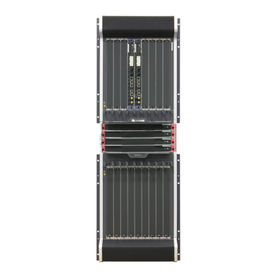
The ME60-X16 has an integrated chassis, with main components which all support hot swapping. The ME60-X16 supports all the Line Processing Units (LPUs) on the former ME60, but the Main Processing Units (MPUs) and Switch and Fabric Units (SFUs) are new. -
Page 21: System Architecture
2 ME60-X16 Chassis Overview 2.1.2 System Architecture This section describes the system architecture. The ME60-X16 adopts a system architecture shown in Figure 2-2. In this architecture, the data plane, management and control plane, and monitoring plane are separated. This design helps to improve system reliability and facilitates upgrading of each plane separately. -
Page 22: Components Of The Me60-X16
Queries about alarm prompts, alarm indications, running status, and alarm status of the voltage and ambient temperature 2.1.4 Components of the ME60-X16 The ME60-X16 has an integrated chassis, with main components which all support hot swapping. Figure 2-3 shows the architecture and main components of the ME60-X16. -
Page 23: Slot Layout On The Me60-X16
12. Rear cable trough 13. Power monitoring 14. Ground terminal module 2.1.5 Slot Layout on the ME60-X16 Figure 2-4 shows the slot layout on the ME60-X16. Figure 2-4 Slot layout on the ME60-X16 17 18 5 6 7 9 10 11... -
Page 24: System Configuration
Slot number:On the ME60-X16, the slots of LPUs are numbered from 1 to 16. The slot number increases from left to right and from top to bottom, facing the front panel of the ME60 (there are corresponding marks on the panel). -
Page 25: Power Supply System
This section describes partitioned power supply on the ME60-X16. As shown in Figure 2-5, the ME60-X16 backplane is divided into four areas, with each area having two power inputs. These eight power inputs work in backup mode. Issue 02 (2012-11-15) Huawei Proprietary and Confidential Copyright ©... -
Page 26: Dc Power Supply System
HUAWEI ME60 Multiservice Control Gateway Hardware Description 2 ME60-X16 Chassis Overview Figure 2-5 Schematic diagram of the power supply for the ME60-X16 17 18 9 10 11 13 14 15 16 2.2.3 DC Power Supply System This section describes the appearance, functions, and technical parameters of the DC power supply module. - Page 27 The lightning protection link of the power module failed. l The power modules does not have input power. If the ME60-X16 has a DC power supply system, eight 70 A PEMs work in 4+4 backup mode. Figure 2-7 shows details of the DC power supply system.
- Page 28 HUAWEI ME60 Multiservice Control Gateway Hardware Description 2 ME60-X16 Chassis Overview Figure 2-7 Architecture of the ME60-X16 DC power supply system area 1 area 2 backplane DC a1 PEMA1 area 2 DC b1 PEMB1 DC a2 PEMA2 area 1 DC b2...
-
Page 29: Ac Power Supply System
Figure 2-9 Rear view of the AC power supply system Figure 2-10 diagrams the AC power supply system of the ME60-X16. The input AC power is converted into regulated DC power by an AC/DC converter. The resulting DC power output is connected to the PEMs through external cables to supply power for all boards and fan modules. - Page 30 Figure 2-10, each DC power input contains one -48 V power input and one RTN input. Two separated RTN inputs are joined on the board. Figure 2-10 Architecture of the ME60-X16 AC power supply system area 1 area 2 AC1 AC2...
-
Page 31: Heat Dissipation System
The middle area of the ME60-X16 is for SFU slots.The air intake vent of this area is located on the left of the chassis. Two upper SFU slots in the area draw in air from the left. When flowing to the right, the air joins the air from the upper chassis. -
Page 32: Air Intake Vent
HUAWEI ME60 Multiservice Control Gateway Hardware Description 2 ME60-X16 Chassis Overview Figure 2-11 Air flow in the ME60-X16 2.3.2 Air Intake Vent This section describes the air intake vents. The ME60-X16 has three air channels. The upper and lower chassis have separate air channels that draw air from the front and exhausts air from the rear. - Page 33 HUAWEI ME60 Multiservice Control Gateway Hardware Description 2 ME60-X16 Chassis Overview Two fan modules each containing one fan are located side by side at the air exhaust vent. If a single fan fails, the system can still work normally for a short period of time at ambient temperature of 40°C ( 104°F ).
-
Page 34: Air Filter
2 ME60-X16 Chassis Overview 2.3.4 Air Filter The ME60-X16 draws in air from the front and exhausts air from the rear. The two air filters on the upper and lower chassis are identical. To maximize air intake, the filters are fully perforated. -
Page 35: Switching Network
The switching network responsible for switching data between LPUs is a key component of the ME60. The ME60 uses switching chips developed by Huawei and Memory-Crossbar-Memory (M-C-M) to provide a three-level switching mode. Level-1 and level-3 switching use a shared- memory model and are performed on LPUs;... -
Page 36: Switch Fabric Unit B
Decision Reliability The ME60-X16 has four SFUs that work in 3+1 load balancing mode. The four SFUs load balance services at the same time. When one SFU is faulty or being replaced, the other three SFUs automatically take over its tasks to ensure normal delivery of services,thus improving system reliability. - Page 37 HUAWEI ME60 Multiservice Control Gateway Hardware Description 2 ME60-X16 Chassis Overview Figure 2-16shows the appearance of the Switch Fabric Unit B(SFUI-200-B). Figure 2-16 Appearance of the Switch Fabric Unit B(SFUI-200-B) Panel Figure 2-17 shows the appearance of the panel. Figure 2-17 Appearance of the Panel 1.
-
Page 38: 40Gbps Switch Fabric Unit B
HUAWEI ME60 Multiservice Control Gateway Hardware Description 2 ME60-X16 Chassis Overview NOTE The Switch Fabric Unit B (SFUI-200-B) can be used only on the ME60-X16, and cannot be used together with the BSUA or MSUA. 2.4.3 40Gbps Switch Fabric Unit B Appearance... -
Page 39: Control Plane
2.5.1 Introduction to the Control Plane This section describes the functions of the control plane. The control plane of the ME60-X16 is separated from the data plane and the monitoring plane. The MPU on the ME60-X16 is responsible for system control and management, including route calculation, device management and maintenance, and device monitoring. -
Page 40: Main Processing Unit B4
HUAWEI ME60 Multiservice Control Gateway Hardware Description 2 ME60-X16 Chassis Overview Data storage: The MPU provides two interfaces for CF cards, which serve as mass storage devices to store data files. System Clock Unit As the system clock unit, the MPU provides accurate and reliable SDH clock signals for LPUs. - Page 41 HUAWEI ME60 Multiservice Control Gateway Hardware Description 2 ME60-X16 Chassis Overview Panel Figure 2-21 shows the appearance of the panel. Figure 2-21 Appearance of the panel 1. Ejector lever 2. CLK/Serial 3. CLK/1PPS 4. CLK/TOD 5. AUX 6. Console 7. MGMT-ETH 8.
- Page 42 HUAWEI ME60 Multiservice Control Gateway Hardware Description 2 ME60-X16 Chassis Overview Indicator/Button Description CF ACT indicator (green) If the indicator is on, the CF is in position. If the indicator is blinking, data is being read or written. If the indicator is off, the CF is not in position or can be removed.
- Page 43 HUAWEI ME60 Multiservice Control Gateway Hardware Description 2 ME60-X16 Chassis Overview Interface Name Connector Type Description CLK/1PPS It is used to input or output 2-Mbit/s clock signals, 2-MHz clock signals, or 1 PPS signals. CLK/Serial It is used to input or output 2-Mbit/s clock signals, 2-MHz clock signals, or RS232 signals.
- Page 44 HUAWEI ME60 Multiservice Control Gateway Hardware Description 2 ME60-X16 Chassis Overview Table 2-14 lists the console interface attributes. Table 2-14 Console interface attributes Attribute Description Connector type RJ45 Operation mode Duplex Universal Asynchronous Receiver/Transmitter (UART) Electrical RS-232 attribute Baud rate...
-
Page 45: Physical Specifications
2.6 Physical Specifications This section describes the specifications of the chassis and boards. 2.6.1 Chassis Specifications This section describes the physical parameters of the ME60-X16. Table 2-18 lists the physical parameters of the ME60-X16. Table 2-18 Physical parameters of the ME60-X16... - Page 46 Short-term operation means that the continuous operation time does not exceed 48 hours and the accumulated operation time per year does not exceed 15 days. Otherwise, it is called long-term operation. Table 2-19 lists the typical configuration of the ME60-X16. Table 2-19 Typical configuration of the ME60-X16 Platform...
-
Page 47: Board Specifications
HUAWEI ME60 Multiservice Control Gateway Hardware Description 2 ME60-X16 Chassis Overview 2.6.2 Board Specifications Table 2-20 lists the specifications of boards supported by the ME60-X16. Table 2-20 Specifications of boards supported by the ME60-X16 Type Description ME0D0MPUB470 ME0DSFUI407B ME0DSFUIE07B Versatile Service Process... - Page 48 HUAWEI ME60 Multiservice Control Gateway Hardware Description 2 ME60-X16 Chassis Overview Type Description 6-Port 1000Base-X-SFP Flexible Card E Motherboard MSUF-21 Flexible Card Multi Service Unit(MSUF-21,2 sub-slots) FPIC MSUF-21 1-port 10GBase LAN/WAN-XFP FPIC 12-port 100Base-FX/1000Base-X-SFP FPIC 1-port OC-192c/STM-64c POS-XFP FPIC Broadband Service Unit...
- Page 49 HUAWEI ME60 Multiservice Control Gateway Hardware Description 2 ME60-X16 Chassis Overview Type Description Broadband Service Unit 4-Port 10GBase WAN/LAN-XFP Broadband Service Unit Integrated BSUI-41 Integrated(BSUI-41) 40-Port 100/1000Base-X-SFP Broadband Service Unit Integrated(BSUI-41) 2-Port 10GBase WAN/LAN-XFP+20-Port 100/1000Base- X-SFP Broadband Service Unit Integrated(BSUI-41)
-
Page 50: Me60-X8 Chassis Overview
3.1 Overview This section gives an overview of the ME60-X8 hardware. 3.2 Power Supply System This chapter describes the power supply system of the ME60-X8. 3.3 Heat Dissipation System This section describes the appearance, functions, and specifications of the heat dissipation system. -
Page 51: Overview
The ME60-X8 has an integrated chassis, with main components which all support hot swapping. The ME60-X8 supports all the Line Processing Units (LPUs) on the former ME60, but the Switch and Route Processing Units (SRUs) and Switch and Fabric Units (SFUs) are new. -
Page 52: System Features
Figure 3-2 Diagram of the system architecture 3.1.3 System Features This section describes the main features. The ME60-X8 provides the following system features: Unblocked switching network that can be upgraded, with switching capacity at the Tbit/s level Distributed hardware-based forwarding and fast service deployment... -
Page 53: Components Of The Me60-X8
Queries about alarm prompts, alarm indications, running status, and alarm status of the voltage and ambient temperature 3.1.4 Components of the ME60-X8 The ME60-X8 has an integrated chassis, with main components which all support hot swapping. Figure 3-3 shows the architecture and main components of the ME60-X8. -
Page 54: Slot Layout On The Me60-X8
12. Handle 13. CMU 14. Mounting ear 3.1.5 Slot Layout on the ME60-X8 Figure 3-4 shows the slot layout on the ME60-X8. Figure 3-4 Slot layout on the ME60-X8 2 3 4 5 6 7 2 3 4 5 6 7 8... -
Page 55: System Configuration
3 ME60-X8 Chassis Overview NOTE Slot number:On the ME60-X8, the slots of LPUs are numbered from 1 to 8. The slot number increases from left to right facing the front panel of the ME60 (there are corresponding marks on the panel). -
Page 56: Power Supply System
This section describes partitioned power supply on the ME60-X8. As shown in Figure 3-5, the ME60-X8 backplane is divided into two areas, with each area having two power inputs. These four power inputs work in backup mode. Figure 3-5 Schematic diagram of the power supply for the ME60-X8... -
Page 57: Dc Power Supply System
The lightning protection link of the power module has failed. l The power modules does not have input power. If the ME60-X8 has a DC power supply system, four 70 A PEMs work in 2+2 backup mode. Figure 3-7 shows details of the DC power supply system. - Page 58 Figure 3-7, each DC power input contains one -48 V power input and one RTN input. Two separated RTN inputs are joined on the board. Figure 3-7 Architecture of the ME60-X8 DC power supply system area 1 area 2 Boards...
-
Page 59: Ac Power Supply System
Figure 3-9 Rear view of the AC rectifier module Figure 3-8 diagrams the AC power supply system of the ME60-X8. AC power input is converted into regulated DC power by an AC/DC converter. The resulting DC power output is connected to the PEMs through external cables to supply power for all boards and fan modules. - Page 60 Figure 3-10, each DC power input contains one -48 V power input and one RTN input. Two separated RTN inputs are joined on the board. Figure 3-10 Architecture of the ME60-X8 AC power supply system area 1 area 2 Boards...
-
Page 61: Heat Dissipation System
This section describes the ME60-X8's system air channel. The ME60-X8 draws in air from the front and exhausts air from the rear. The air intake vent is located above the board area on the front chassis; the air exhaust vent is located above the board area on the rear chassis. -
Page 62: Air Intake Vent
3 ME60-X8 Chassis Overview 3.3.2 Air Intake Vent An air filter is installed over the air intake vent of the ME60-X8. The air filter has a curved face, large area, and small windage resistance. These features help to improve heat dissipation efficiency. -
Page 63: Air Filter
3.3.4 Air Filter The ME60-X8 draws in air from the front top and exhausts air from the rear top. There is a 3 U space in the upper part of the chassis and an air filter on the front of the chassis. To maximize air intake, the filter is fully perforated. -
Page 64: Switching Network
The switching network responsible for switching data between LPUs is a key component of the ME60. The ME60 uses the switching chips developed by Huawei and Memory-Crossbar- Memory (M-C-M) to provide a three-level switching mode. Level-1 and level-3 switching adopts the shared-memory model and is performed on LPUs;... -
Page 65: 200Gbps Switch Fabric Unit C(Sfui-200-C)
Decision Reliability The ME60-X8 has three SFUs. Two SFUs are integrated on two SRUs. Another SFU, is a separate SFU. These three SFUs work in 2+1 load balancing mode.The three SFUs load balance services at the same time. When one SFU is faulty or being replaced, the other two SFUs automatically take over its tasks to ensure normal delivery of services, thus improving system reliability. - Page 66 HUAWEI ME60 Multiservice Control Gateway Hardware Description 3 ME60-X8 Chassis Overview Figure 3-15 Appearance of the SFUI-200-C Panel Figure 3-16 shows the appearance of the panel. Figure 3-16 Appearance of the panel 1. Ejector lever 2. ACT indicator 3. OFL button 4.
-
Page 67: 40Gbps Switch Fabric Unit C
3 ME60-X8 Chassis Overview NOTE The SFUI-200-C can be used only on the ME60-X8, and cannot be used together with the BSUA or MSUA. The SFUI-200-C can be used only together with the 200G Switch and Route Processing Unit A5. -
Page 68: Control Plane
3.5.1 Introduction to the Control Plane This section describes the functions of the control plane. The control plane of the ME60 is separated from the data plane and the monitoring plane. The SRU is used by the ME60-X8. The SRU integrates an SFU used for data switching. -
Page 69: Switch And Route Processing Unit A5
HUAWEI ME60 Multiservice Control Gateway Hardware Description 3 ME60-X8 Chassis Overview Data configuration: The SRU stores configuration data, startup files, charging information, upgrade software, and system logs. Data storage: The SRU provides two interfaces for CF cards, which serve as mass storage devices to store data files. - Page 70 HUAWEI ME60 Multiservice Control Gateway Hardware Description 3 ME60-X8 Chassis Overview NOTE In this document, the equipment exterior is for reference only. The actual equipment may differ from what is shown in the figures. Panel Figure 3-20 shows the appearance of the panel.
- Page 71 HUAWEI ME60 Multiservice Control Gateway Hardware Description 3 ME60-X8 Chassis Overview Indicator/ Description Button ACT active/ If the indicator is steady on, the SRU is in the active state. standby indicator If the indicator is off, the SRU is in the standby state.
- Page 72 HUAWEI ME60 Multiservice Control Gateway Hardware Description 3 ME60-X8 Chassis Overview Interface Name Connector Description Type Console interface RJ45 It connects to the console for on-site configuration of the system. AUX interface RJ45 It connects to the Modem for remote maintenance through dialing.
- Page 73 HUAWEI ME60 Multiservice Control Gateway Hardware Description 3 ME60-X8 Chassis Overview Attribute Description Operation mode 10M/100M/1000M auto-sensing interfaces, supporting half-duplex and full-duplex modes Standard IEEE 802.3-2002 compliance Cable Category 5 unshielded twisted pair (UTP) cables recommended when the specification interface rate is 10 Mbit/s or 100 Mbit/s; super category 5 Shielded...
-
Page 74: Switch And Route Processing Unit A4
G.703 compliance NOTE The Switch and Route Processing Unit A5 can be used only on the ME60-X8. The 200G Switch and Route Processing Unit A5 can be used only together with the SFUI-200-C. 3.5.3 Switch and Route Processing Unit A4... - Page 75 HUAWEI ME60 Multiservice Control Gateway Hardware Description 3 ME60-X8 Chassis Overview Figure 3-21 Appearance of the SRU NOTE In this document, the equipment exterior is for reference only. The actual equipment may differ from what is shown in the figures.
- Page 76 HUAWEI ME60 Multiservice Control Gateway Hardware Description 3 ME60-X8 Chassis Overview Table 3-18 Buttons and indicators on the panel of the SRU Indicator/ Description Button OFL button To remove a board, you must press and hold the button for six seconds until the OFL indicator turns on.
- Page 77 HUAWEI ME60 Multiservice Control Gateway Hardware Description 3 ME60-X8 Chassis Overview Table 3-19 Interfaces on the SRU and their uses Interface Name Connector Description Type USB interface It is not used and reserved. CF card interface TYPE II It is used to hold a CF card to store data files as a massive storage device.
- Page 78 HUAWEI ME60 Multiservice Control Gateway Hardware Description 3 ME60-X8 Chassis Overview Attribute Description Cable Single-mode or multi-mode fibers specification Table 3-21 lists the 10Base-T/100Base-TX/1000Base-T-RJ45 interface attributes. Table 3-21 10Base-T/100Base-TX/1000Base-T-RJ45 interface attributes Attribute Description Connector type RJ45 Operation mode 10M/100M/1000M auto-sensing interfaces, supporting half-duplex and...
- Page 79 G.703 compliance NOTE The Switch and Route Processing Unit A4 can be used only on the ME60-X8. The 40G Switch and Route Processing Unit A4 can be used only together with the SFUI-40-C. Issue 02 (2012-11-15) Huawei Proprietary and Confidential...
-
Page 80: Physical Specifications
3 ME60-X8 Chassis Overview 3.6 Physical Specifications This chapter describes the specifications of the chassis and boards. 3.6.1 Chassis Specification Table 3-26 lists the physical parameters of the ME60-X8. Table 3-26 Physical parameters of the ME60-X8 Item Description Dimensions (width x depth x 442 mm x 650 mm x 620 mm ( 17.40 in. -
Page 81: Board Specifications
2*Fan+4*DC Power+2*SRU+1*SFU+8*LPUF40+16*2-Port10GE FPIC 100G 2*Fan+4*DC Power+2*SRU200A+1*SFU200C+8*LPUF100 +16*5-Port10GE FPIC 3.6.2 Board Specifications Table 3-28 lists the specifications of boards supported by the ME60-X8. Table 3-28 Specifications of boards supported by the ME60-X8 Type Description ME0D0SRUA470 ME0D0SRUA570 Issue 02 (2012-11-15) Huawei Proprietary and Confidential... - Page 82 HUAWEI ME60 Multiservice Control Gateway Hardware Description 3 ME60-X8 Chassis Overview Type Description ME0DSFUI407C ME0DSFUIE07C Versatile Service Process Unit C Flexible Card Versatile ME0MVSUF1010 Service Unit 10(VSUF-10) Integrated Versatile Service ME0DVSUI201A Unit 20 A(VSUI-20-A) ME01VSUA0 Motherboard BSUF-10 Flexible Card Broadband Service Unit(BSUF-10,four...
- Page 83 HUAWEI ME60 Multiservice Control Gateway Hardware Description 3 ME60-X8 Chassis Overview Type Description Broadband Service Unit 20-Port 1000Base-X-SFP Broadband Service Unit Integrated BSUI-21/ Integrated (BSUI-21) MSUI-21 2-Port 10GBase WAN/LAN-XFP Broadband Service Unit Integrated(BSUI-21) 1-Port 10GBase WAN/LAN-XFP+10-Port 1000Base-X- SFP Broadband Service Unit Integrated(BSUI-21)
- Page 84 HUAWEI ME60 Multiservice Control Gateway Hardware Description 3 ME60-X8 Chassis Overview Type Description Motherboard MSUF-100 Flexible Card Multi Service Unit(MSUF-100,4 sub-slots) FPIC MSUF-100 1-Port OC-768c/STM-256c POS-2KM-LC Flexible Card 5-Port 10GBase LAN/WAN-SFP+ Flexible Card (BP100,Occupy two sub-slots) Multi Service Unit 10-Port 10GBase LAN/WAN-XFP Multi Service Unit...
-
Page 85: Me60-X3 Chassis Overview
4.1 Overview This section gives an overview of the ME60-X3 hardware. 4.2 Power Supply System This chapter describes the power supply system of the ME60-X3. 4.3 Heat Dissipation System This section describes the appearance, functions, and specifications of the heat dissipation system. -
Page 86: Overview
The ME60-X3 adopts a centralized routing engine and a distributed forwarding architecture. The ME60-X3 has an integrated chassis, with boards support hot swapping. The ME60-X3 has two types of chassis, namely, the DC chassis and the AC chassis. Figure shows the DC chassis and Figure 4-2 shows the AC chassis. -
Page 87: System Features
Queries about alarm prompts, alarm indications, running status, and alarm status of the voltage and ambient temperature 4.1.3 Components of the ME60-X3 The ME60-X3 has an integrated chassis with main components which all support hot swapping. Figure 4-3 shows the components of the ME60-X3 DC chassis. - Page 88 4. Rack-mounting ear 5. Air intake vent 6. Handle 7. Power module 8. Air filter 9. Ground terminal 10. Fan Figure 4-4 Components of the ME60-X3 AC chassis CONS OLE CF CARD RESE T LINK OFL CFS CONS OLE CF CARD...
-
Page 89: Slot Layout On The Me60-X3
An interface is numbered in the format of slot number/card number/port number NOTE Slot number: On the ME60-X3, the slots of LPUs are numbered from 1 to 3. The slot number increases from bottom to top, facing the front panel of the ME60 (there are corresponding marks on the panel). -
Page 90: Power Supply System
The slots are for LPUs (optional). Number of MPU slots 4.2 Power Supply System This chapter describes the power supply system of the ME60-X3. 4.2.1 Architecture of the Power Supply System This section describes the features of the power supply system. -
Page 91: Dc Power Supply System
One of the power modules does not have input power. The following is the introduction to the PEM. The PEM of the ME60-X3 has one straight-through power input that provides the following functions: Issue 02 (2012-11-15) Huawei Proprietary and Confidential... -
Page 92: Ac Power Supply System(Epw30B-48A)
4.2.4 AC Power Supply System(EPW30B-48A) This section describes the appearance, functions, and the technical parameters of the AC power supply module. The AC power module of the ME60-X3 as shown in Figure 4-8. Figure 4-8 Appearance of the AC power module Table 4-5 describes the indicators on the AC power module. - Page 93 4.3 Heat Dissipation System This section describes the appearance, functions, and specifications of the heat dissipation system. 4.3.1 System Air Channel This section describes the ME60-X3's system air channel. Issue 02 (2012-11-15) Huawei Proprietary and Confidential Copyright © Huawei Technologies Co., Ltd.
- Page 94 Fans on power modules 4.3.2 Air Intake Vent An air filter is installed over the air intake vent of the ME60-X3. The air filter has a curved face, large area, and small windage resistance. These features help to improve heat dissipation efficiency.