Table of Contents
Advertisement
Quick Links
DVD PLAYER
DV-535
THIS MANUAL IS APPLICABLE TO THE FOLLOWING MODEL(S) AND TYPE(S).
Model
Type
DV-535
‡
WYXJ
‡
WYXJ/SP
‡
WVXJ
‡
WYXQ
‡
RDXJ/RB
‡
RDXJ/RD
‡
RDXJ1/RA
CONTENTS
1. SAFETY INFORMATION ....................................... 2
2. EXPLODED VIEWS AND PARTS LIST ................. 4
4. PCB CONNECTION DIAGRAM ........................... 32
5. PCB PARTS LIST ................................................ 42
6. ADJUSTMENT ..................................................... 46
PIONEER CORPORATION
PIONEER ELECTRONICS SERVICE, INC. P.O. Box 1760, Long Beach, CA 90801-1760, U.S.A.
PIONEER EUROPE NV Haven 1087, Keetberglaan 1, 9120 Melsele, Belgium
PIONEER ELECTRONICS ASIACENTRE PTE. LTD. 253 Alexandra Road, #04-01, Singapore 159936
c
PIONEER CORPORATION 2000
POWER
-OFF -ON
Power Requirement
AC220-240V
AC220-240V
AC220-240V
AC220-240V
AC110-127/220-240V
AC110-127/220-240V
AC110-127/220-240V
4-1, Meguro 1-chome, Meguro-ku, Tokyo 153-8654, Japan
D VD PLA YER
0
4 1
¡ ¢
7
8
STANDBY
Î A
Region No.
2
2
2
2
2
4
1
7. GENERAL INFORMATION ................................ 47
7.1 DIAGNOSIS .................................................. 47
PICKUP DEFECTIVE ........................... 47
7.1.2 TEST POINTS LOCATION ................... 48
7.1.3 TEST MODE SCREEN DISPLAY ........ 49
7.1.4 TROUBLE SHOOTING ........................ 53
7.1.5 ERROR CODE ..................................... 54
7.1.6 DISASSEMBLY .................................... 58
7.2 IC .................................................................. 61
3
ORDER NO.
RRV2316
The voltage can be converted by
the following method.
-------------
-------------
-------------
-------------
Automatic select
Automatic select
Automatic select
T - ZZE JUNE 2000 Printed in Japan
Advertisement
Table of Contents

Related Manuals for Pioneer DV-535WYXJ


Summary of Contents for Pioneer DV-535WYXJ
-
Page 1: Table Of Contents
PIONEER CORPORATION 4-1, Meguro 1-chome, Meguro-ku, Tokyo 153-8654, Japan PIONEER ELECTRONICS SERVICE, INC. P.O. Box 1760, Long Beach, CA 90801-1760, U.S.A. PIONEER EUROPE NV Haven 1087, Keetberglaan 1, 9120 Melsele, Belgium PIONEER ELECTRONICS ASIACENTRE PTE. LTD. 253 Alexandra Road, #04-01, Singapore 159936 PIONEER CORPORATION 2000 T –... -
Page 2: Safety Information
The use of a substitute replacement component which does Leakage 0.5mA current Device not have the same safety characteristics as the PIONEER tester under recommended replacement one, shown in the parts list in test this Service Manual, may create shock, fire, or other hazards. - Page 3 DV-535 WARNING! THE AEL(ACCESSIBLE EMISSION LEVEL) OF THE LASER POWER OUTPUT IS LESS THAN CLASS 1 BUT THE LASER COMPONENT IS CAPABLE OF EMITTING RADIATION EXCEEDING THE LIMIT FOR CLASS 1. A SPECIALLY INSTRUCTED PERSON SHOULD DO SERVICING OPERATION OF THE APPARATUS. LASER DIODE CHARACTERISTICS FOR DVD : MAXIMUM OUTPUT POWER : 5 mW WAVELENGTH : 655 nm...
-
Page 4: Exploded Views And Parts List
DV-535 2. EXPLODED VIEWS AND PARTS LIST • NOTES: Parts marked by "NSP" are generally unavailable because they are not in our Master Spare Parts List. • mark found on some component parts indicates the importance of the safety factor of the part. Therefore, when replacing, be sure to use parts of identical designation. - Page 5 DV-535 (1) PACKING PARTS LIST Mark No. Description Part No. Mark No. Description Part No. Power Cord See Contrast table (2) Operating Instructions See Contrast table (2) Audio Cord (L = 1.5m) See Contrast table (2) (German/French) Video Cord (L = 1.5m) See Contrast table (2) Operating Instructions See Contrast table (2)
- Page 6 DV-535 2.2 EXTERIOR SECTION WYXJ, WYXJ/SP, WVXJ and WYXQ Types Only Refer to "2.3 LOADING MECHANISM ASSY". To LOAB Assy CN101...
- Page 7 REC1263 Chassis VNA2160 Rear Panel See Contrast table (2) Tray VNL1858 DVD Plate VAM1088 Pioneer Name Plate VAM1099 Tray Panel VNK4591 Front Panel Assy See Contrast table (2) • • • • • Pop Label See Contrast table (2) Bonnet Case S...
- Page 8 DV-535 2.3 LOADING MECHANISM ASSY To DVDM Assy Refer to "2.4 TRAVERSE MECHANISM ASSY-S". To DVDM Assy To DVDM Assy LOADING MECHANISM ASSY PARTS LIST Mark No. Description Part No. Mark No. Description Part No. 1 Traverse Mechanism Assy-S VXX2653 Loading Motor Assy VXX2505 2 LOAB Assy...
- Page 9 DV-535 2.4 TRAVERSE MECHANISM ASSY-S • Top View DVDM Assy TRAVERSE MECHANISM ASSY-S PARTS LIST Mark No. Description Part No. Mark No. Description Part No. SMEB Assy VWG2048 Hook VNL1770 FGSB Assy VWG2009 FFC Holder VNL1802 Motor (CARRIAGE) VXM1079 Mechanism Base VNL1806 Motor (SPINDLE) VXM1084...
-
Page 10: Block Diagram And Schematic Diagram
DV-535 3. BLOCK DIAGRAM AND SCHEMATIC DIAGRAM 3.1 BLOCK DIAGRAM 36/16M (24P) (24P) ADAI(AC3) SPDL ADAO MOTOR OEIC RF IC SD0-SD7 MPEG2 DSPRF 18,19 18,19 B1-B4 VOUT 57-60 78,80-84 22,23 22,23 DECODER DECODER 63-66 86,87 YOUT LA9701M F_RTN BY CHIP AV-1 SREQ TRKG... - Page 11 DV-535 (4P) (4P) (30P) (30P) CN103 CN801 FL TUBE PWSB CN102 KEY2 V101 AODAI ASSY VAW1056 KEY0 Q601 S802 POWER FL CONTROL IC101 PE5185A (4P) (4P) KEYB CN104 CN701 KEY0 ASSY KEY1 JA491 SELIR SR IN REMOTE SENSOR WYXJ, WYXJ/SP, WVXJ, WYXQ TYPES ONLY JA535 RGB OUT SCRB ASSY...
- Page 12 DV-535 3.2 LOAB, SMEB, FGSB ASSYS and OVERALL WIRING DIAGRAM PWSB ASSY KEYB ASSY (VWG2174) (VWG2176) RDXJ/RB,RDXJ/RD, RDXJ1/RA TYPES ONLY 1/3- FLJB ASSY (VWV1777: WYXJ, WYXJ/SP, WVXJ, WYXQ) (VWV1776: RDXJ/RB, RDXJ/RD, RDXJ1/RA) RDXJ/RB,RDXJ/RD, RDXJ1/RA TYPES ONLY WYXJ, WYXJ/SP, WVXJ, WYXQ TYPES ONLY CN110 SCRB ASSY (VWV1744)
- Page 13 DV-535 Note : When ordering service parts, be sure to refer to "EXPLODED VIEWS and PARTS LIST" or "PCB PARTS LIST". : RF SIGNAL ROUTE : FOCUS SERVO LOOP LINE : TRACKING SERVO LOOP LINE POWER SUPPLY UNIT : SLIDER SERVO LOOP LINE (VWR1330) POWER CORD XDG3001: WYXJ, WYXJ/SP, WYXQ...
- Page 14 DV-535 3.3 DVDM ASSY (1/3) DVDM ASSY (VWS1438: WYXJ, WYXJ/SP, WVXJ, WYXQ) (VWS1412: RDXJ/RB, RDXJ/RD, RDXJ1/RA) BA4510F CHECKER CHIP (DVD) (DVD) DTC114EUA (CD) RF IC DKN1193 S3B-PH-SM3 SPDL & FTS DRIVER CN101 LOADING MOTOR S2B-PH-SM3 ASSY CN202 VKN1763...
- Page 15 DV-535 : The power supply is shown with the marked box. : RF SIGNAL ROUTE RESISTOR : ROM DATA SIGNAL ROUTE : FOCUS SERVO LOOP LINE CAPACITOR : TRACKING SERVO LOOP LINE : SLIDER SERVO LOOP LINE BA4510F WYXJ, WYXJ/SP, WVXJ, WYXQ RDXJ/RB, RDXJ/RD, RDXJ1/RA Not used 10k (DVD) (DVD)
- Page 16 DV-535 3.4 DVDM ASSY (2/3) DVDM ASSY (VWS1438: WYXJ, WYXJ/SP, WVXJ, WYXQ) (VWS1412: RDXJ/RB, RDXJ/RD, RDXJ1/RA) RESISTOR CAPACITOR WORK SRAM (1M) KM68V1000CLT-7L FLASH MEMORY (4M) VYW1727 4M DRAM BY CHIP DVD DATA PROCESSOR (DVD)
- Page 17 DV-535 : The power supply is shown with the marked box. : RF SIGNAL ROUTE : ROM DATA SIGNAL ROUTE 1/3, 3/3 : AUDIO SIGNAL ROUTE 1/3, 3/3 20MHz SYSTEM CONTROL CPU R501 R502 WYXJ, WYXJ/SP, WVXJ, WYXQ Not used Not used VKN1626 RDXJ/RB, RDXJ/RD, RDXJ1/RA CN102...
- Page 18 DV-535 3.5 DVDM ASSY (3/3) AV-1 MPEG2 DECODER 12 15 (VCB) (VCB) 13 16 (VCB) (VCB) 16M SDRAM RGB ENCODER WYXJ, WYXJ/SP,WVXJ WYXQ TYPES ONLY...
- Page 19 DV-535 DVDM ASSY (VWS1438: WYXJ, WYXJ/SP, WVXJ, WYXQ) (VWS1412: RDXJ/RB, RDXJ/RD, RDXJ1/RA) : AUDIO SIGNAL ROUTE : ROM DATA SIGNAL ROUTE (VCB) : V/CB SIGNAL ROUTE : Y SIGNAL ROUTE : C SIGNAL ROUTE CLOCK : R SIGNAL ROUTE GENERATOR : G SIGNAL ROUTE : B SIGNAL ROUTE RESISTOR...
- Page 20 DV-535 3.6 FLJB (1/3), KEYB and PWSB ASSYS FLJB ASSY (VWV1777: WYXJ, WYXJ/SP, WVXJ, WYXQ) (VWV1776: RDXJ/RB, RDXJ/RD, RDXJ1/RA) R143 20k: WYXJ, WYXJ/SP,WVXJ, WYXQ 68k: RDXJ/RB, RDXJ/RD,RDXJ1/RA FL CONTROL MICROCOMPUTER FL TUBE KEYB ASSY PWSB ASSY S701 : 0 (OPEN/CLOSE) S802 : POWER STANDBY/ON S702 : 4...
- Page 21 DV-535 PWSB ASSY CN103 CN801 04R-FJ 04P-FJ (VWG2174) ASG7013 CN104 CN701 KEYB ASSY (VWG2176) 04R-FJ 04P-FJ S701-S706 : ASG7013 CN101 14P-FJ CN101 CN102 VKN1627 3 → 5 CONVERTER 5 → 3 CONVERTER : The power supply is shown with the marked box.
- Page 22 DV-535 3.7 FLJB ASSY (2/3) FLJB ASSY (VWV1777: WYXJ, WYXJ/SP, WVXJ, WYXQ) (VWV1776: RDXJ/RB, RDXJ/RD, RDXJ1/RA) 2ch DAC Q601...
- Page 23 DV-535 : AUDIO SIGNAL ROUTE 2SA1037K WYXJ, WYXJ/SP, WVXJ, WYXQ TYPES ONLY CN110 VKN1267 For DOWNLOAD...
- Page 24 DV-535 3.8 FLJB ASSY (3/3) FLJB ASSY CN106 VKN1627 (VWV1777: WYXJ, WYXJ/SP, WVXJ, WYXQ) (VWV1776: RDXJ/RB, RDXJ/RD, RDXJ1/RA) : AUDIO SIGNAL ROUTE (VCB) : V/CB SIGNAL ROUTE : Y SIGNAL ROUTE : C SIGNAL ROUTE : R SIGNAL ROUTE : G SIGNAL ROUTE : B SIGNAL ROUTE CN15 (VCB)
- Page 25 DV-535 JA491 RKN1004 RDXJ/RB, WYXJ, WYXJ/SP, RDXJ/RD, WVXJ, WYXQ RDXJ1/RA TYPES ONLY YPES ONLY JA403 JA401 VKB1154 VKB1147 (OUT2 OUT) (OUT1,2 (OUT1 OUT) OUT) JA402 VKB1146 VSEL SIGNAL WYXJ, WYXJ/SP, WVXJ, WYXQ TYPES ONLY RDXJ/RB, RDXJ/RD, RDXJ1/RA TYPES ONLY 3IN 6OUT VIDEO AMP 5.1k (CR) (CB)
- Page 26 DV-535 3.9 SCRB ASSY (WYXJ, WYXJ/SP, WVXJ and WYXQ TYPES ONLY) SCRB ASSY (VWV1744) (WYXJ, WYXJ/SP, WVXJ, WYXQ TYPES ONLY) CN201 : AUDIO SIGNAL ROUTE : V SIGNAL ROUTE : Y SIGNAL ROUTE : C SIGNAL ROUTE (R/C) : R SIGNAL ROUTE : G SIGNAL ROUTE : B SIGNAL ROUTE (V/Y)
- Page 27 DV-535 (R/C) (R/C) (V/Y) (V/Y) CHASSIS (R/C) (R/C) (V/Y) (V/Y)
- Page 28 DV-535 3.10 POWER SUPPLY UNIT (VWR1331) POWER SUPPLY UNIT (VWR1331) Note : When the fuse(F001) on VWR1331 blow out, VWR1331 might be damaged. At that time, exchange VWR1331 for VWR1330.
- Page 29 DV-535 NOTE OF SPARE PARTS IN POWER SUPPLY (SYPS) UNIT • In case of repairing, use the described parts only to prevent an accident. • Please write the red mark on the board when the primary section of POWER SUPPLY (SYPS) Unit is repaired. •...
- Page 30 DV-535 3.11 POWER SUPPLY UNIT (VWR1330)
- Page 31 DV-535 WAVEFORMS Note : The encircled numbers denote measuring point in the schematic diagram. Measurement condition : No. 1 to 4 and 6 to 11 : MJK1, Title 1-chp 1 No. 5 : CD, ABEX-784 Track 1 No. 12 to 14 : MJK1, Title 1-chp 4 No.
-
Page 32: Pcb Connection Diagram
DV-535 4. PCB CONNECTION DIAGRAM NOTE FOR PCB DIAGRAMS : 1. Part numbers in PCB diagrams match those in the schematic 3. The parts mounted on this PCB include all necessary parts for diagrams. several destinations. 2. A comparison between the main parts of PCB and schematic For further information for respective destinations, be sure to diagrams is shown below. - Page 33 DV-535 4.2 SCRB ASSY SCRB ASSY SIDE A CN201 Q602 Q601 Q502 Q501 VNP1764-A : WYXJ, WYXJ/SP, WVXJ, RDXJ/RB, RDXJ/RD, RDXJ1/RA Types VNP1786-A : WYXQ Type SCRB ASSY SIDE B IC301 Q103 Q102 IC401 Q203 Q204 Q201 Q202 Q101...
- Page 34 DV-535 4.3 DVDM ASSY • This PCB is a four-layered board. DVDM ASSY IC5 IC8 IC11 IC15 Q121 Q101 Q7 Q6 IC21 Q103 Q5 Q102 IC18 Q109 Q107 Q91 Q83 VNP1760-A : WYXJ, WYXJ/SP, WVXJ, RDXJ/RB, RDXJ/RD, RDXJ1/RA Types VNP1776-A : WYXQ Type SIDE A...
- Page 35 DV-535 CN102 • This PCB is a four-layered board. DVDM ASSY LOADING MOTOR ASSY IC13 IC14 IC12 Q112 PICKUP ASSY IC19 Q114 Q113 Q131 Q106 IC26 IC27 CN202 Q251 Q85 Q89 Q87 VNP1760-A : WYXJ, WYXJ/SP, WVXJ, RDXJ/RB, RDXJ/RD, RDXJ1/RA Types VNP1776-A : WYXQ Type CN106 CN101...
- Page 36 DV-535 4.4 FLJB, KEYB and PWSB ASSYS FLJB ASSY PWSB ASSY KEYB ASSY VNP1761-B : WYXJ, WYXJ/SP, WVXJ, RDXJ/RB, RDXJ/RD, RDXJ1/RA Types VNP1775-B : WYXQ Type IC150 IC102 IC101 E F G...
- Page 37 DV-535 CN101 IC301 IC201 IC491 Q291 IC302 CN535 CN15...
- Page 38 DV-535 FLJB ASSY Q253 Q601 IC602 Q570 IC401 Q431 Q362 Q363 Q361 Q261 Q254 Q259 Q258 Q260 Q331 IC201 IC301 Q292 IC202 Q256 Q257 IC210 Q281 Q255 IC303 IC203 IC302 Q301 Q351-Q353 Q354...
- Page 39 DV-535 PWSB ASSY KEYB ASSY VNP1761-B : WYXJ, WYXJ/SP, WVXJ, RDXJ/RB, RDXJ/RD, RDXJ1/RA Types VNP1775-B : WYXQ Type Q363 Q361 Q261 IC104 IC103 IC101 Q500 Q531 IC501 Q541 Q421 Q401 Q411 Q551 Q521 Q501 Q511...
- Page 40 DV-535 4.5 POWER SUPPLY UNIT (VWR1330) AC IN POWER SUPPLY UNIT IC201 IC103 Q401 IC102 CN101 Q402 Q410 Q412 Q411 SIDE A...
- Page 41 DV-535 4.6 POWER SUPPLY UNIT (VWR1331) AC IN POWER SUPPLY UNIT MC201 Q201 IC102 CN101 IC101 VR101 Q101 SIDE A...
-
Page 42: Pcb Parts List
DV-535 Mark No. Description Part No. Mark No. Description Part No. 5. PCB PARTS LIST • NOTES: Parts marked by "NSP" are generally unavailable because they are not in our Master Spare Parts List. • mark found on some component parts indicates the importance of the safety factor of the part. Therefore, when replacing, be sure to use parts of identical designation. - Page 43 DV-535 Mark No. Description Part No. Mark No. Description Part No. Part No. Mark Symbol and Description Remarks VWS1438 VWS1412 R833 RS1/16S3902F Not used R834, R835 RS1/16S1801F Not used R836, R837 RS1/16S1001F Not used R838 (0Ω) DCN1106 Not used R839 RS1/16S103J Not used R845-R847...
- Page 44 DV-535 Mark No. Description Part No. Mark No. Description Part No. D301 KV1471E PARTS LIST for DV-535/WYXJ RB501V-40 D665,D666 RB521S-30 LOAB ASSY SWITCH COILS S101 VSK1011 L150,L330 CHIP COIL LCYA100J2520 L304 CHIP COIL LCYA2R7J2520 CHIP COIL VTL1067 OTHERS L85,L911 CHIP BEADS VTL1084 CN101 KR CONNECTOR S3B-PH-K-S...
- Page 45 DV-535 Mark No. Description Part No. Mark No. Description Part No. RESISTORS COILS AND FILTERS R123 (39Ω) ACN7047 L401,L411,L421,L501,L511 LAU120J-TA R732,R733,R735,R736 (47kΩ) ACN7077 L521 LAU120J-TA R632 (100Ω) DCN1092 L101 LAU680J-TA R608,R609,R613,R624,R627 (10kΩ) DCN1094 L601 NOISE FILTER RTF1167 R629,R631,R633,R638,R654 (10kΩ) DCN1094 SWITCH R657,R658,R664,R706 (10kΩ) DCN1094...
-
Page 46: Adjustment
DV-535 Mark No. Description Part No. Mark No. Description Part No. X101 CERAMIC RESONATOR VSS1142 POWER SUPPLY UNIT (VWR1330) (5MHz) OTHERS P101 PROTECTOR (800mA) AEK7063 KEYB ASSY P102 PROTECTOR (1.6A) AEK7066 FU101 FUSE (2.5A) REK1102 SWITCHES S701-S706 ASG7013 POWER SUPPLY UNIT (VWR1331) RESISTORS OTHERS All Resistors... -
Page 47: General Information
DV-535 7. GENERAL INFORMATION 7.1 DIAGNOSIS 7.1.1 SELF-DIAGNOSTIC FUNCTION OF PICKUP DEFECTIVE Symptom • Indicates "No Disc" in FL display. • Player does not playback, etc.. Procedure of Self-Diagnosis → 1 Press the TEST buttons (of the test mode remote control unit : GGF1067) in the test mode screen, and turn on the laser diode (It light-up for nine seconds.). -
Page 48: Test Points Location
DV-535 7.1.2 TEST POINTS LOCATION DVDM ASSY VCODR IC13 IC14 C707 SREQ TP3 (TE) IC19 TP1 (FE) VREF TP2 (RFO) IC27 IC26 VREF TP4 (FDO) R389 Short-circuit at diagnosis Front Side CN15 SIDE B... -
Page 49: Test Mode Screen Display
DV-535 7.1.3 TEST MODE SCREEN DISPLAY TEST MODE SCREEN DISPLAY Consecutive double-OSD display is supported during test mode. The screen is composed 10 lines with a maximum of 32 characters per line. It can't be used with the debugging display mode together. •... - Page 50 DV-535 (10) Output video system [V – ∗ ∗ ∗ ∗] (20) 1 Version of the flash ROM [V : ∗ . ∗ ∗ ∗] 2 Flash ROM size [FLSH = ∗] NTSC system [NTSC] PAL system [PAL ] (21) Revision of the system controller [S : ∗ . ∗ ∗ ∗ / ∗ . ∗ ∗ ] Auto-setting [AUTO] Skirt terminal output [SK –...
- Page 51 DV-535 DEBUGGING SCREEN SPECIFICATION FOR THE MECHANISM CONTROLLER • This specifications is subject to change without notice. 1 Indication Method of The Mechanism Controller Debugging Screen A debugging screen of the mechanism controller is indicated when pressing the test mode remote control unit [GGF1067] in order of the buttons.
- Page 52 DV-535 15. Disc distinction threshold value (CD and unrecorded 27. It indicates the frequency that entered the internal disc) circumference plunging into backup of the sled Threshold value of the disc distinction. Distinguish it from Hexadecimal number indication. Counter does not reset till CD if bigger than this value, and distinguish it from an turns the power off after turning it on.
-
Page 53: Trouble Shooting
DV-535 7.1.4 TROUBLE SHOOTING • No Power ON • FL is not turned ON • FL indication is unusual START • Blow out fuse of the primary side Power ON • Blow out micro-fuse on the POWER SUPPLY Assy. (Check the each voltage.) (KU, KC : P202, P204, P205, P201) (Others : P611, P211, P711) •... -
Page 54: Error Code
DV-535 7.1.5 ERROR CODE Error codes that are displayed on the FL display without using the remote control unit FL Display Possible causes Operation of the unit The sound may not out AV1 VER AV-1 chip is not a match with the program of system controller with the specific audio. - Page 55 DV-535 Description Causes if with a DVD Causes if with a CD Operation of the of Error SGC converge SGC could not converge during detects the peak Open timeout 41 Spindle timeout The unit did not enter Stop mode within 10 seconds of issuance of a Stop command. Stop The spindle could not converge into within ±...
- Page 56 DV-535 Description Causes if with a DVD Causes if with a CD Operation of the Unit of Error ID can not read An ID could not be read for 1 second or more. Stop during tracing Subcode check No frame could be read for 3 Stop failure during seconds or more.
- Page 57 DV-535 Error codes that are displayed on the FL display by using the remote control unit (Device error) To display : ESC + DISPLAY + DISPLAY ; Location of the display : At the two digits of left of the FL display Description of Error Causes if with a DVD Causes if with a CD...
-
Page 58: Disassembly
DV-535 7.1.6 DISASSEMBLY DIAGNOSIS OF PCBS Note When diagnosing the unit, be sure to use two connection cables for service. (Part No : GGD1228) Bonnet, Tray Panel Front Panel Assy Remove the Bonnet (Screws × 8) Front Panel Assy Unhook Unhook (×3) (×3) - Page 59 DV-535 Short Circuit R389 Diagnosis (1) Put the AC Power Cord POWER SUPPLY Unit FLJB Assy PWSB Assy Short circuit R389 Power ON KEYB Assy DVDM Assy DVDM Assy Loading Mechanism Assy (Bottom View) Note ; 1 : When does not short-circuit with R389, playback will not be possible after the next steps.
- Page 60 DV-535 DISASSEMBLY OF TRAVERSE MECHANISM ASSY-S Remove the Bonnet (Screws × 8) Bridge Unhook (×2) Power ON Tray Tray Open (0) Pull out the AC Power Cord POWER SUPPLY Short Open ASSY side Short SW Pickup Flexible Cable Unhook Unhook Traverse Mechanism Assy-S (Top View)
- Page 61 DV-535 7.2 IC • The information shown in the list is basic information and may not correspond exactly to that shown in the schematic diagrams. • List of IC LC78652W, PD3410A, MB86373B, PE5185A LC78652W (DVDM ASSY : IC2) • DSP IC •...
- Page 62 DV-535 • Pin Function t f i − − l l i t t i y t i t l i − − − − a i l t l i −...
- Page 63 DV-535 r r i t i r − − − − l a i t f i − − l l i l i f − t l i f t l i f t l i f − − −...
- Page 64 DV-535 PD3410A (DVDM ASSY : IC11) • System Control IC • Pin Function − − − − − − − c t i − − − − − − − ← − − − − − − − c t i −...
- Page 65 DV-535 − − − − − − − c t i − − c t i − c t i c t i c t i c t i − c t i − − − − − − − −...
- Page 66 DV-535 − t i s d i l t i s − − − − − − − l l o l a i e l l l a i e l l − e l l − − − −...
- Page 67 DV-535 − − − − − − − − − −...
- Page 68 DV-535 MB86373B (DVDM ASSY : IC18) • MPEG2 Decoder IC • Block Diagram Exclusive 16Mbit Parallel port SDRAM Input Signal Memory System Controller Block Interface Decoder Block Internal Video Sub- Sync. Decoder picture Control Block Block Starting Signal Control Reset Picture Block Signal...
- Page 69 DV-535 • Pin Function − " ( : " L " : " i g i − i g i i g i i g i ) t i − − − i g i - t l − ) t i −...
- Page 70 DV-535 − − − − t l i f t l i f t l i f − , y l o " . " − , y l o " . " − , y l o " . " −...
- Page 71 DV-535 − − − − − − − − − − − " " L y l l − − − − − − − −...
- Page 72 DV-535 PE5185A (FLJB ASSY : IC101) • FL Control IC • Pin Function − − − n i l − − − − − t s i t s i − − − − − − − − − − −...
- Page 73 DV-535 − c t i n i l − − − − − t s i − −...
-
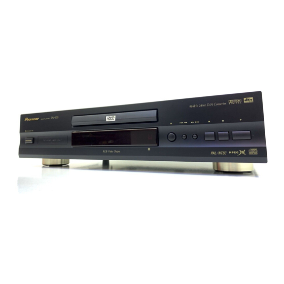
Page 74: Panel Facilities And Specifications
DV-535 8. PANEL FACILITIES AND SPECIFICATIONS 8.1 PANEL FACILITIES Front Panel DVD PLAYER ¡ ¢ STANDBY/ON ÎA 3 (play) button STANDBY/ON button Press to switch the player on or to put in standby. Press to start or resume playback. ¡ ¢ (forward) button Disc tray When loading a disc, place discs in the disc tray with the label Press to advance to chapters/tracks. - Page 75 DV-535 Display Window 6 7 8 9 DOLBY DIGITAL CONDITION LAST TOTAL MEMO REMAIN TITLE VCD indicator CONDITION indicator VCD lights when a Video CD is loaded. CD lights when an Indicates that Condition Memory settings are memorized for audio CD is loaded. the currently loaded DVD.
- Page 76 CONTROL IN jack Use to connect this player to another component bearing the Pioneer Î mark. This lets you control this unit as though it were a component in a system. Player operations are then performed by pointing the remote control at the component...
- Page 77 Use to connect this player to another component bearing the on the disc as is. Pioneer Î mark. This lets you control this unit as though it were a component in a system. Player operations are then performed by pointing the remote control at the component that the player is connect to.
- Page 78 DV-535 Remote Control (Buttons indicated with * are used for menu operation.) LAST MEMORY button You can resume DVD or Video CD playback from the point you last watched even if the disc is removed from the player. Press OPEN/ LAST MEMORY during playback to set a Last Memory point.
- Page 79 DV-535 ¡ STEP/SLOW e/E buttons 1 REV/FWD ¡ (fast reverse/forward) buttons Press STEP/SLOW E during playback to view slow playback. During playback of DVD and Video CD, press In pause mode, press STEP/SLOW E to advance DVDs and FWD ¡ to perform fast forward scanning. Press REV 1 to Video CDs frame by frame and STEP/SLOW e to back up a perform fast reverse scanning of DVD and Video CD.
- Page 80 DV-535 8.2 SPECIFICATIONS Accessories Specifications Audio cord ..................1 Video cord ..................1 WYXJ, WYXJ/SP, WVXJ and WYXQ types Power cord ..................1 General Remote control unit ............... 1 System ...... DVD system and Compact Disc digital audio system AA (R6P) dry cell batteries ............. 2 Power requirements ........
- Page 81 DV-535 Accessories Specifications Remote control unit ............... 1 AA (R6P) dry cell batteries ............. 2 RDXJ/RB, RDXJ/RD and RDXJ1/RA types Audio cord ..................1 Video cord ..................1 General Power cord ..................1 System ...... DVD system and Compact Disc digital audio system Operating Instructions ..............