Table of Contents
Advertisement
Quick Links
Electromagnetic Flowmeter CAPACITANCE TYPE
NOTES
Before using the equipment, please read this manual carefully and understand the
contents, and then use the equipment correctly.
• NEVER attempt to operate the equipment in any ways that are not described in this
instruction manual.
• After reading this manual, store it with care in a place where it can be referred to
whenever needed.
• Please be sure that this manual is delivered to the personnel who will use this
product.
MODEL LF516 / LF546
INSTRUCTION MANUAL
6 F 8 A 0 9 3 4
Advertisement
Table of Contents
Troubleshooting

Related Manuals for Toshiba LF516


Summary of Contents for Toshiba LF516
- Page 1 • After reading this manual, store it with care in a place where it can be referred to whenever needed. • Please be sure that this manual is delivered to the personnel who will use this product. MODEL LF516 / LF546 6 F 8 A 0 9 3 4...
- Page 2 We thank you very much for your purchase of our LF516/LF546 CAPACITANCE TYPE series electromagnetic flowmeter. This instruction manual describes the notes on using an electromagnetic flowmeter , installation, configuration and maintenance. It is intended for the personnel in charge of installation, operation and maintenance.
-
Page 3: Safety Precautions
SAFETY PRECAUTIONS Safety signs and labels affixed to the product and/or described in this manual give important information for using the product safely. They help prevent damage to property and obviate hazards for persons using the product. Make yourself familiar with signal words and symbols used for safety signs and labels. Then read the safety precautions that follow to prevent an accident involving personal injury, death or damage to property. - Page 4 SAFETY PRECAUTIONS (continued) Safety Precautions for Hazardous Locations Do not disconnect while circuit is live unless location is known to be nonhazardous. Live part of electric circuit or a high temperature department can cause explosion. DON’T Do not modify or disassemble the enclosure. Strength degradation and defects of enclosure can cause explosion.
- Page 5 Use an appropriate device to carry and install the LF516/LF546. If this product falls to the ground, injury, or malfunction of or damage to the product, can be caused. Do not modify or disassemble LF516/LF546 unnecessarily. Modifying or disassembling this product can cause electric shock, malfunction of or damage to this DON’T...
- Page 6 Warranty and Limitation of Liability Toshiba does not accept liability for any damage or loss, material or personal, caused as a direct or indirect result of the operation of this product in connection with, or due to, the occurrence of any event of force majeure (including fire or earthquake) or the misuse of this product, whether intentional or accidental.
-
Page 7: Handling Precautions
Handling Precautions To obtain the optimum performance from LF516/LF546 flowmeter for years of continuous operation, observe the following precautions. (1) Do not store or install the flowmeter in : ・Where there is direct sunlight. ・Where excessive vibration or mechanical shock occurs. - Page 8 Handling Precautions (continued) (6) Observe the following precautions when you open the converter housing cover: • Do not open the cover in the open air unprotected against rain or wind. This can cause electric shock or cause damage to the flowmeter electronics. •...
-
Page 9: Table Of Contents
Product Inspection and Storage... 11 Product Inspection... 11 Storage... 11 Overview... 12 Names of Parts... 13 Appearance OF LF516/LF546... 13 Construction of the terminal blocks... 14 Installation... 15 Notes on Selecting the Installation Location... 16 Mounting Procedure ... 17 4.2.1 Pipe checks... - Page 10 Parameter Setting Items... 53 Check/Change of Parameters ... 54 8.2.1 Menu Configuration Selection Screen ... 54 8.2.2 Exciting Current Value... 55 8.2.3 Meter Size ... 56 8.2.4 Exciting Frequency... 58 8.2.5 Flow Direction Setting... 58 8.2.6 Display Setting ... 59 8.2.7 Custom Coefficient Setting ...
- Page 11 11. Communications Function ... 131 11.1 Connections with HHT Terminal ... 131 11.2 Procedures for Communication with HHT ... 132 11.3 Notes on Communications ... 133 12. Self-Diagnosis and Alarms ... 134 12.1 Self-Diagnosts ... 134 12.2 Output Status for Errors and Alarms... 137 13.
-
Page 12: Product Inspection And Storage
Inspect the flowmeter for indications of damage that may have occurred during shipment. Make sure the type and specifications of the flowmeter are in accordance with the ordered specifications. If you cannot find the items listed above or any problem exists, contact your nearest Toshiba representative. 1.2 Storage... -
Page 13: Overview
2. Overview LF516/LF546 electromagnetic flowmeter can be use in the following hazardous (classified) locations. ClassⅠ, Division 2, Groups A, B, C and D, ClassⅡ, Division 2, Groups E, F and G ClassⅢ This product is electromagnetic flowmeter that measure the volumetric flow rate of conductive fluid using Faraday's law of electromagnetic induction. -
Page 14: Names Of Parts
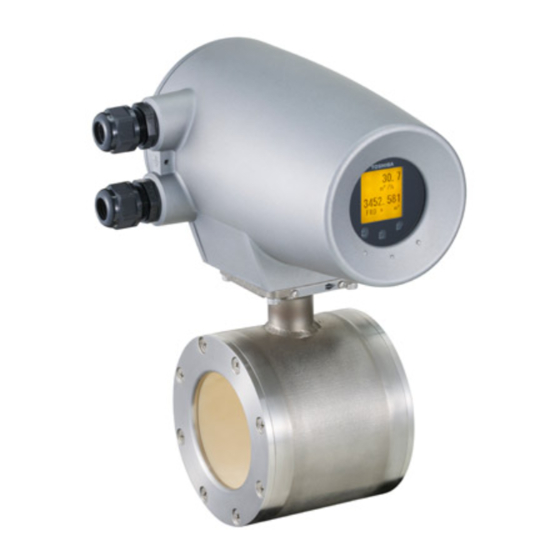
Terminal block cover Ground terminal Converter For power cable For current output cable Raised portion Detector Figure 3.1.1 Appearance of LF516/LF546 − 13 − 6 F 8 A 0 9 3 4 Display section Control key (Control panel) Arrow nameplate... -
Page 15: Construction Of The Terminal Blocks
3.2 Construction of the terminal blocks Terminal Block Construction of LF546 Converter When you remove the terminal block cover shown in the figure "Appearance of LF516/LF546", you can see the converter terminal block as shown below. Power supply terminal Fuse... -
Page 16: Installation
If his product falls to the ground, injury, or malfunction of or damage to the product, can be caused. Ground the LF516/LF546 independently from power equipment. (100 ohm or less ground resistance) Operating this product without grounding can cause electric shock or malfunction. -
Page 17: Notes On Selecting The Installation Location
4.1 Notes on Selecting the Installation Location This product is designed for the following environment. ・Indoor and outdoor installation ・Altitude:Up to 2000m ・Regulation of power voltage:±10% ・Pollution degree 2 Do not store or install the flowmeter in : Places within the immediate proximity of equipment producing electrical interference (such as motors, transformers, radio transmitters, electrolytic cells, or other equipment causing electromagnetic or electrostatic interference). -
Page 18: Mounting Procedure
4.2 Mounting Procedure Avoid places within the immediate proximity of equipment producing electrical interference (such as motors, transformers, radio transmitters, electrolytic cells, or other equipment causing electromagnetic or electrostatic interference). Avoid places where excessive pipe vibration occurs. Avoid places where fluid runs in a pulsating form. Avoid places where there is direct sunlight. - Page 19 6 F 8 A 0 9 3 4 (2) Preventing an Empty Pipe Condition Fix the relevant pipes installed on both sides of the detector by attach fittings, etc. to support the pipe. By supporting the pipes, not only the pipe vibration is reduced but also the damage to the pipes by the electromagnetic flowmeter's weight and the fluid mass (see Figures 4.2 and 4.3).
-
Page 20: Installation Procedure
4.2.2 Installation Procedure To mount the LF516/LF546, place it between the upstream and downstream pipe flanges and tighten it with flange bolts and nuts. See Figure 4.4 and follow the procedure below: 1. Insert two lower mounting bolts through the clearance holes in the upstream (or downstream) pipe flange. - Page 21 Table 4.1 Bolt length and Nut tightening torque ANSI class 150 Through Bolts Meter size Dia- P.C.S meter 15mm 1/2” 1/2” 25mm 1” 1/2” 40mm 1 1/2” 1/2” 50mm 2” 5/8” 80mm 3” 5/8” 100mm 4” 5/8” DIN/BS 10, DIN/BS 16 Through Bolts Meter size Dia-...
-
Page 22: Piping Connections
4.3 Piping Connections (1) Required Pipe Length If various joints are used upstream of the detector outlet, the straight pipe length as shown in Table 4.2 is required. Table 4.2 Required straight pipe length on the upstream side L=5D (1) 90°bent (2) Tee (3) Diffuser (4) Fully opened sluice valve... - Page 23 (2) Pipe Orientation The detector may be installed in horizontal, vertical or sloping pipe runs as shown in Figure 4.5. However, except for horizontal installation, fluid should flow from lower to upper directions. See Figure 4.5. Detector Figure 4.5 Detector Piping Orientation The electrodes should be positioned horizontally against the ground surface in any piping installation.
- Page 24 (3) Flow Direction Install the detector in accordance with the flow direction arrow on the detector. See Figure 4.7. If the actual flow runs opposite to the specified flow direction, the following display and output appears. For single range measurement, ・LCD display: ・Outut: For bidirectional range measurement, the flow in opposite direction results in a positive...
-
Page 25: Grounding
• If the piping material is conductive, connect the grounding wires to the both ends of the piping flange. Figure 4.10 Grounding the LF516/LF546 Type CAUTION Do not work on piping and wiring with wet hands. Wet hands may result in electric shock. -
Page 26: Wiring
5. Wiring Notes on wiring DO NOT DISCONNECT WHILE CIRCUIT IS LIVE UNLESS LOCATION IS KNOWN TO BE NONHAZARDOUS. Live part of electric circuit or a high temperature department can cause explosion. DON’T Do not activate circuits while assembly of all components is not over. Protective performance degradation for hazardous location can cause explosion. - Page 27 Install a switch and fuse to isolate the LF516/LF546 from mains power. Power supply from mains power can cause electric shock or circuit break-down. Do not work on piping and wiring with wet hands. Wet hands may result in electric shock DON’T...
-
Page 28: Cables
CAUTION (1) Select the cable run location so they are away from electrical equipment (motors, transformers, or radio transmitters) which causes electromagnetic or electrostatic interference. (2) Deterioration of flowmeter circuit insulation occurs if the converter interior or cable ends get wet or humidified. -
Page 29: External Device Connections And Grounding
5.2 External Device Connections and Grounding The terminal board connections of LF516/LF546 Flowmeter are shown in Figure 5.1. Proceed with wiring as described in Section 5.4, “Wiring Procedure.” Ground terminal IV wire 5.5mm or more (100 ohm or less ground resistance) Converter unit Figure 5.1 External Wiring Schematic Diagram... -
Page 30: Notes On Wiring
5.3 Notes on Wiring Notes on Instrumentation-Converter Wiring • To avoid 2-point grounding, ground the shield of output cable basically at the receiving side. • Use a grounding wire of IV wire 5.5mm Do not share a grounding wire with other instruments where grounding current may flow. (An independent grounding is preferable.) •... -
Page 31: Wiring
5.4 Wiring IMPORTANT The cable connections are not provided in the conduit port of this apparatus. Please prepare yourself for the cable connections which could be used in Division2 hazardous locations. Do not wire cables and replace parts when power is supplied. Wiring work and replacing parts in the power-on state may cause electric shock. -
Page 32: Cable Connection
5.4.2 Cable Connection Connect and install the terminal-treated cables to the terminal block by the following procedure. *Connect the cables to the terminal block securely. A loose connection may cause incorrect measurement. After connecting a cable, try to pull it to check whether it has been connected securely. -
Page 33: Digital I/O Connections
5.5 Digital I/O Connections Digital I/O terminals consist of contact output terminals (DO1 and DO2), voltage signal input terminal (DI), and signal common terminal (COM). Each terminal (DO1, DO2 and DI) is isolated from internal circuits. Terminal (COM) is the signal common for the other three terminals (DO1, DO2 and DI). Functions can be assigned for each terminal with the LCD control keys. -
Page 34: Operation
6. Operation Do not touch the terminal board when power is supplied. Touching the terminal board when power is supplied can cause electric shock. DON’T 6.1 Preparatory check Follow the procedure described below to prepare before starting the flow measurement System Check Check the items listed below Check the wiring between the converter and related instruments. -
Page 35: Zero Adjustment
Note 1: If the detector pipe is not filled with the fluid to be measured, the flow rate will be indefinite and unable to be measured. Before using the flowmeter, be sure to fill the detector pipe the fluid to be measured. 6.2 Zero Adjustment To conduct zero adjustment of the flowmeter, the fluid in the detector pipe must be held still. -
Page 36: Lcd Display And Controls
7. LCD Display and Controls 7.1 Name and Function of Each Part of LCD Display The LDC display and infrared switches (hereafter, called "control key") in front of the converter allows you to view or set various constants such as measured values and parameters. Instructions The operation principle of infrared switch is to irradiate infrared to the front of control panel and detect the reflection from finger when operating. - Page 37 ● LCD electronically rotatable display 8-line × 14-character liquid crystal display. The backlit display provides an easy-to-read indication even under poor lighting conditions. Instantaneous flow rates or totalized flow in the measurement mode or configuration parameters in the setting mode can be displayed. (Number of LCD display dots: 128 x 128 dots) ①...
- Page 38 ● Setting switch The control keys allow you to perform converter control and setting, without opening the converter housing. These three controls keys function differently depending on the current display screen. The functions of these control keys are displayed on the display screen. In this product, the display method can be changed according to the converter installation direction.
-
Page 39: Display Format
7.2 Display Format In the measurement mode, the measured data is displayed using the menu items set by the Display 1 (DSPL1) and Display 2 (DSPL2). (For display settings, see 8.2.6 "Display Setting.") Flow rate / Flow velocity display - 1 0 . 0 0 m / s Totalized flow count display 1 2 3 4 5 6 7 8... - Page 40 Note 1: Totalized flow volume and totalized difference flow volume are displayed to the least significant digit of the set count rate. (Example1) When the count rate is 0.0001 m When the measurement object flows through 0.0001(m Because inside counter is 8 digits at the maximum, the maximum of totalized flow is 9999.999(m to 0, and continue totalization.
- Page 41 Percent display - 1 2 5 . 0 Flow rate (When custom unit is selected) - 1 0 . 0 0 * X X X / Y Y Y Range display 1 0 . 0 0 0 m / s In the range display, the range currently used is displayed (any one of the ranges 1 to 4).
- Page 42 Bar graph display Bar graph can be set only for Display 2. * About Range type, percent display and percent value when bar graph is displayed When percent display is used, the % value displayed depends on the flow direction. However, the % value when bar graph is displayed is as shown in the table below.
-
Page 43: Basic Operations
7.3 Basic operations 7.3.1 Mode Change The converter provides the setting mode and calibration mode as well as the measurement mode. To change the mode to the setting mode or to the calibration mode, push the measurement mode, push the ●... - Page 44 ○Flow of mode change Note: When the screen is switched, let your finger off the switch. If you keep pushing, the Measurement mode mode returns to the measurement mode. 1.000 Hold down only the center switch for 3 seconds or longer. (Note) 12345678 Unlock procedure error(3 times) PUSH SW...
- Page 45 ○ Pulse output setting mode This mode is used to perform continuous parameter settings (automatic operation) regarding pulse outputs. When these parameters are set, pulse output is ready to send out. MENU SEL DO1 FUNC BASIC DETAILED PLS OUT PREVIEW PLS SET ZERO ADJ PLS SET...
- Page 46 ○ Explanation about mode change The converter usually works continuously in the measurement mode. If you want to set parameters or perform calibration or adjustment, you have to go to the setting mode. To enter the setting mode, push the center switch for 3 seconds or more in the measurement mode.
-
Page 47: Setting And Calibration
○ Operation timeout function If no operation is made for one minute or more while the converter is in the setting mode, the mode automatically returns to the measurement mode unless the parameters are displayed on the screen. Menu screen Parameter check screen Parameter change screen (Parameters... - Page 48 Switch operation Display example A:DETECTOR 1 EXC CUR 2 SIZE 3 EXC FREQ 4 FLOW DIR 5 EXIT B:DISPLAY 1 DSPL1 2 DSPL2 3 CS VAL 4 CS UNIT 5 EXIT B:DISPLAY 1 DSPL1 2 DSPL2 3 CS VAL 4 CS UNIT 5 EXIT B:DISPLAY 1 DSPL1...
- Page 49 Switch operation Display example 10.0000 10.0000 10.0000 10.0000 05.0000 05.0000 SET OK? 10.0000 − 48 − 6 F 8 A 0 9 3 4 Description Push to select the item you want to check or change. The screen changes and the currently set item appears for you to check.
- Page 50 Switch operation Display example 5.00000 C:RANGE 1 R TYPE 2 R1 3 R2 4 R3 5 R4 6 R HYS 7 EXIT C:RANGE 1 R TYPE 2 R1 3 R2 4 R3 5 R4 6 R HYS 7 EXIT EXIT OK? 5.000 12.345 −...
-
Page 51: Configuration Items Selection Table
7.4 Configuration Items Selection Table How to check or change each constant of the converter is shown in the table below. Details of each item are described in the setting items (A to R) of Chapter 8, "Parameter Settings." ○ Basic configuration (when menu configuration is BASIC) When you select "BASIC"... - Page 52 ○ Detailed configuration When you select "DETAILED" in the menu configuration selection screen, the check/change menu for each constant setting is expanded as shown in the table below. Function Exciting Meter size DETECTOR Current *1 Display1 Display2 DUSPLAY Range type Range1 *1 RANGE Damping...
-
Page 53: Password Input
7.5 Password input The converter provides the password function to prohibit some functions that affect the flow measurement from being set or adjusted. For the protected functions, see the menu configuration table on the previous page. * Password is a 3-digit number. If '000' is set for the password, the password input screen does not appear. If a password is set (other than '000' is set), you have to enter your correct password. -
Page 54: Parameter Settings
8. Parameter Settings 8.1 Parameter Setting Items To check or change each constant of the converter, first select the desired setting item described in 7.3.2 “Setting and Calibration.” Proceed as follows for settings in the setting mode. 8.2.2 Exciting current 8.2.3 Meter size 8.2.4... -
Page 55: Check/Change Of Parameters
8.2 Check/Change of Parameters 8.2.1 Menu Configuration Selection Screen Display example MENU SEL BASIC DETAILED PREVIEW ZERO ADJ PLS SET You can select the kind of menu configuration. For menu items of configuration, see 7.4 "Setting and Calibration Items List." BASIC DETAILED PREVIEW... -
Page 56: Exciting Current Value
8.2.2 Exciting Current Value The exciting current value can be checked/changed by the following procedures. Be sure to match the exciting current value with the value specified for the combined detector. Specifying any other value may cause an error. Shown below is an example of changing the exciting current value from 0.1900A to 0.2150A. Switch operation STEP1 STEP2... -
Page 57: Meter Size
Switch operation STEP6 STEP7(=END) Note: The setting range of excitation current value is from 0.0000A to 0.3200A. If you try to set an exciting current value larger than 0.3200A, an error message appears and the setting value returns to the previous value. 8.2.3 Meter Size Proceed as follows to check the meter size of the detector. - Page 58 Note 1:The meter size display loops as shown below: 25mm 40mm ① 1inch 1.5inch ② Note 2: When the meter size is changed, range unit and count rate will be forcefully changed as described below. If necessary, change these parameters again. Range unit If the count rate goes out of the setting range Count rate...
-
Page 59: Exciting Frequency
8.2.4 Exciting Frequency Proceed as follows to check the Exciting Frequency Switch operation STEP1 8.2.5 Flow Direction Setting In the converter, you can set the flow direction of fluid arbitrarily. ● Flow direction setting Selection item NORMAL SWITCH Switch operation Display example A:DETECTOR Select "EXC FREQ"... -
Page 60: Display Setting
Switch operation STEP1 STEP2 STEP3 STEP4 STEP5(=END) 8.2.6 Display Setting You can select one of the engineering units listed below as a flow measurement unit. Flow velocity unit Flow rate unit (Note3) Volume unit Other units Totalized flow direction Totalized difference flow Note 1: If COUNT, RANGE, GRAPH or CUSTOM is selected, the display is shown below: Display example FLOW DIR... - Page 61 COUNT: displays the totalized flow counts (up to 8 digits). RANGE: displays the range number being used for measurement (1 to 4). GPARH: displays the measured value (% value) in bar graph. In addition, the range number being used for measurement is also displayed. CUSTOM: displays the result obtained by multiplying m The details see 10.10 “Custom unit function”.
- Page 62 /min For Display 2 unit setting, select DSPL2 from the setting menu. ● How to select the display digit setting When you select flow velocity or flow rate (custom unit is included), the screen automatically moves to the display digit setting screen. Using the display digit setting screen, you can change the decimal places used for the measured value in the measurement mode.
- Page 63 For example, if the setting range is 10m/s and display digit setting is 1/100, the measured value will be displayed to the first decimal place. Setting range=10.0000 m/s Maximum effective digits Likewise, when the setting range 1m/s and display digit setting is 1/100, the measured value will be displayed to the second decimal place.
-
Page 64: Custom Coefficient Setting
Note: The setting item for the third unit (flow volume direction code) changes cyclically as shown below. B(bi-directional) For Display 2 setting, select DSPL2 from the setting menu. 8.2.7 Custom Coefficient Setting You can set the custom coefficient used when CUSTOM is selected for display setting or span setting. Custom coefficient can be set except 0. -
Page 65: Custom Unit Setting
Switch operation STEP4(=END) Note: The custom coefficient setting precision is 5 digits. Therefore, the input value changes as follows depending on the setting value: (Example) Input value, "85713038" → After the setting is confirmed, "85713040" 8.2.8 Custom Unit Setting You can set the custom unit used when CUSTOM is selected for display setting. For custom unit setting, you can set any combination of characters within 7 characters. -
Page 66: Span (Range)
Switch operation STEP4(=END) Note : The selectable characters are displayed cyclically as shown below: Symbol 1 Numeric characters Symbol 1 Alphabetical characters (uppercase) Alphabetical characters (lowercase) Special character 8.2.9 Span (Range) You can set the following constants in this setting item: (1) Range type (2) Unit of span (can be changed in Range 1) (3) Span... - Page 67 ● Span You can set the span for actual flow rate or flow velocity. (1) Setting range The span can be set within 0.5 m/s to 10 m/s in terms of flow velocity. If you try to set the span outside of this range, either high limit or low limit error message appears: HIGH OVER SPEC (if the set value exceeds 10 m/s) LOW OVER SPEC (if the set value is less than 0.1 m/s)
- Page 68 ● Range hysteresis The hysteresis is the dead band used when multiple ranges are switched. You can set the hysteresis within the range of 0 to 25% in increments of 0.1%. The hysteresis is set only when automatic selection of multiple ranges is used. ●...
- Page 69 Switch operation Display example C:RANGE 1 R TYPE 2 R1 4 R3 5 R4 6 R HYS 7 EXIT ● Changing the range type The range type should be set before changing the span. The following is an example to change the range type from Single range (SINGLE) to Bidirectional automatic selection of multiple ranges (2F-2R).
- Page 70 Switch operation Display example R TYPE STEP5(=END) 2F-2R SET OK? ● Changing the span You can set the span value for each range. The following is an example to change the span of Range 1 from 2.0 m/s to 100 L/min. Switch operation Display example STEP1...
- Page 71 Switch operation Display example STEP6 136.000 STEP7(=END) 100.000 SET OK? Note: Unites of the measuring unit changes as shown below: First unit CUSTOM Second unit (Time unit) ・However, the following first and second unit combinations cannot be selected: m/min, m/h, m/d, ft/min, ft/h, ft/d ・In the case of custom unit, time unit is not displayed.
-
Page 72: Damping Constant
Switch operation STEP3 STEP4(=END) Note: If you try to set a value exceeding 25.0%, HIGH OVER SPEC error appears and the value returns to the previous value. Set a value once again. 8.2.10 Damping Constant The damping constant is used to moderate output fluctuations. (The larger the damping constant, the more the output is averaged. -
Page 73: Rate-Of-Change Limit And Control Limit Time
Switch operation STEP2 STEP3 STEP4(=END) 8.2.11 Rate-Of-Change Limit and Control Limit Time The rate-of-change limit is used to control sudden changes of the converter’s flow rate signal output when excessive noise is contained in the flow rate signal. The rate-of-change limit (set in percent value to the span of measuring range) and control limit time (set in second) are used, and if the flow rate signal sampling value exceeds the rate-of-change limit value based on the previous average value of the flow rate signal, the converter rejects the sampling value and outputs the average value including the maximum value of the rate-of-change value. - Page 74 ● Changing the rate-of-change limit The following is an example to change the rate-of-change limit value from 10.0% to 15.0%. Switch operation Display example D:FILTER 1 DAMPING 2 LIM RATE 3 LIM TIME 4 EXIT LIM RATE STEP1 LIM RATE STEP2 LIM RATE STEP3...
-
Page 75: Low Cutoff
8.2.12 Low Cutoff The low cutoff is the function to set the current output to zero forcefully if the flow rate is equal to or less than the low cutoff value set near 0%. The low cutoff value can be set within the range 0 to 10% in increments of 0.1%. You can check or change the low cutoff value as described below. -
Page 76: Display Low Cutoff
8.2.13 Display Low Cutoff When low cutoff is set in 8.2.12 “Low Cutoff,” this function determines whether to use the low cutoff processing for displayed values. You can select the display low cutoff setting from the items in the table below. ●... -
Page 77: Still Water Zero Adjustment
Switch operation STEP4(=END) Note: The measured value sent from the converter through communications is the value processed with display low cutoff. 8.2.14 Still Water Zero Adjustment Zero adjustment is performed with the fluid held still in the detector's measurement pipe. Switch operation STEP1 STEP2... -
Page 78: Manual Zero Adjustment
8.2.15 Manual Zero Adjustment This function is used to perform zero adjustment simply by comparing the output value of the converter with the process value of other instruments without stopping the process of measurement. If zero adjustment described in 8.2.14, “Still Water Zero Adjustment” can be performed, this manual setting is not needed. -
Page 79: 4-20Ma Alarm Output Setting
Switch operation STEP3 STEP4(=END) Note: The manual zero adjustment value can be set within the range equivalent to ±1 m/s (±10 % of the maximum range 10m/s). If you try to set a value out of this range, an error message HIGH OVER SPEC or LOW OVER SPEC appears. If this happen, redo the setting. -
Page 80: Output Low Limit Setting
Switch operation STEP1 STEP2 STEP3 STEP4(=END) 8.2.17 Output Low Limit Setting The low limit of the current output for converter can be set. The output low limit can be selected from the items listed in the table below. ● Output low limit setting function Selection items 4.0mA The current value can be outputted up to 4.0mA (0%). -
Page 81: Digital Output
You can check or change the output low limit as described below. The following is an example to change the output low limit value from 4.0mA to 2.4mA. Switch operation STEP1 STEP2 STEP3 STEP4(=END) 8.2.18 Digital Output Digital output functions can be selected. You can select the digital output function from the tables shown below. - Page 82 ●Digital output functions Selection items NO USE H ALM L ALM HH ALM LL ALM RNG SIG1 RNG SIG2 PRESET C CONV ALM PLS OUT PLS FRD PLS REV MRH ALM MRL ALM Notes: When the range type is set to Forward/reverse multiple ranges, and if the pulse output (PLS OUT) is selected, pulses of forward and reverse directions will be output.
-
Page 83: Digital Input
Switch operation STEP2 STEP3 STEP4(=END) 8.2.19 Digital Input Digital input functions can be selected. You can select the digital input function from the table shown below. For details of digital input functions, see 10, “Functional Description.” ●Digital input functions Selection items NO USE CNT ST/SP CNT RS/ST... - Page 84 ●Digital input control signal You can select the detective level of the digital input, as shown below, to control the totalizer and pulse output. (Only when the digital input function is set for totalizer control input) Selection items Digital input function setting CNT ST/SP (Totalizer START/STOP)...
-
Page 85: Count Rate (Pulse Rate), Pulse Width Setting Mode And Pulse Width
Switch operation STEP4(=END) 8.2.20 Count Rate (Pulse Rate), Pulse Width Setting Mode and Pulse Width In this section, the volume per count (pulse) for totalized flow operation and the pulse width for totalization pulse output can be set. The totalized flow counts is not affected by the display setting but it is recommended that you set a volume unit for Display 1 or Display 2 to check its operation. - Page 86 ● For pulse width setting mode, you can select either AUTO or MANUAL. Depending on this setting, the pulse width setting varies as shown in the table below: Selection item Pulse width value to be set After the count rate is set, the pulse width is automatically set AUTO to 40% of the period of pulse frequency at 100% output.
- Page 87 You can check or change the count rate and pulse width as described below. The following is an example to change the count rate from 0.01m Switch operation Display example CNT RATE STEP1 0.01000 CNT RATE STEP2 0.01000 CNT RATE STEP3 10.0000 CNT RATE...
-
Page 88: Preset Count
Note 1: The units of count rate change cyclically as shown below: m³ Note 2: After the count rate is set, related parameters are automatically set under the following conditions: (1) Pulse width When the pulse width setting mode is AUTO: Pulse width will be automatically set according to the count rate. - Page 89 You can check or change the preset count as described below. The following is an example to change the preset count value from 500 (count) to 1000 (count). Switch operation Display example K:PRESET C 1 PRST VAL 2 OUT MODE 3 EXIT PRST VAL STEP1...
-
Page 90: Preset Mode
8.2.22 Preset Mode The preset mode determines the function when the totalizer reaches the preset count. The present mode can be set from the items shown below. ●Preset mode Selection items HOLD 50ms PLS 500ms PLS Note: If you set the preset mode to "50ms PLS" or "500ms PLS", you need to set the preset count to 1, 2, 5, 25, 125 ×10 preset output timing may be shifted when the totalizer overflows. -
Page 91: Flow Rate High/Low Alarm And High-High/Low-Low Alarm
Switch operation STEP2 STEP3 STEP4(=END) 8.2.23 Flow Rate High/Low Alarm and High-High/Low-Low Alarm The high/low limit, high-high/low-low limit of the flow rate, at which an alarm is generated, can be set as % value of the span flow rate of the set maximum range. The high/low alarm, and high-high/low-low alarm values for flow rate can be set within the range of −10% to 110% (percentage to Range 1) in increments of 0.1%. - Page 92 Switch operation Display example H SET STEP2 H SET STEP3 H SET STEP4(=END) SET OK? ●Changing the high/low alarm value The following is an example to change the high alarm value from +105% to +103%. Switch operation Display example L:H/L ALM1 1 H SET 2 H VAL 3 L SET...
-
Page 93: Mag-Prover-Self Diagnosis On/Off Setting
Switch operation STEP3 STEP4(=END) Note: If you try to set a value outside of the range −10% to +110%, LOW OVER SPEC or HIGH OVER SPEC error appears and the value returns to the previous value. Set a value once again. 8.2.24 Mag-Prover -Self Diagnosis ON/OFF Setting You can select on/off setting for Mag-Prover’s self-diagnosis function. -
Page 94: Fixed Value Output
●Changing the Mag-Prover’s self-diagnosis function setting The following is an example to change the Mag-Prover’s self-diagnosis setting from OFF to ON. Switch operation STEP1 STEP2 STEP3 STEP4(=END) 8.2.25 Fixed Value Output The fixed value output function is used to output a fixed current and/or a fixed pulse output independently of the flow rate signal. - Page 95 Operation when fixed output is set to ON Current output Pulse output Digital output other than pulse output Display Display example: 3 0 0 0 2 0 . 0 First line: Pulse count (5 digits maximum), Unit: (PPS) fixed Second line: Current output (4 digits including a decimal point), Unit: (mA) fixed This fixed value output function does not work in the calibration mode.
- Page 96 Switch operation Display example FIX SET STEP4 SET OK? CUR VAL STEP5 04.0 CUR VAL STEP6 20.0 CUR VAL STEP7 20.0 SET OK? PLS VAL STEP8 00000 PLS VAL STEP9 00100 PLS VAL STEP10(=END) 00100 SET OK? − 95 − 6 F 8 A 0 9 3 4 Description When you push...
-
Page 97: Password Setting
Note 1: If you try to set a value outside of the range, 2.4mA or 24mA (in the case of fixed current output) or 3000pps (in the case of fixed pulse output) will be forcibly set. Note 2: The pulse width set in Section 8.2.20 is used for fixed pulse output. The pulse width must not be greater than 40% of the period of the fixed output set frequency. - Page 98 * However, if a wrong password is entered when the mode is changed from the measuring mode to the setting mode, *** appears and the password cannot be checked. Switch operation Display example PASSWORD ●Changing the password The following is an example to change the password from 123 to 453. Switch operation Display example PASSWORD...
-
Page 99: Lcd Adjustment
8.2.27 LCD Adjustment This section describes how to set the LCD density adjustment value for the converter display. The LCD density can be set in 5 levels. LCD density adjustment level LCD density The LCD density adjustment value is set to "3" when shipped from the factory. The display of the LCD gradually becomes thinner over time. -
Page 100: Switch Position Setting
8.2.28 Switch Position Setting The switch position of the converter display can be set. The position setting of the switch enables the display remains the same in orientation, regardless of which direction relative to the piping the converter is installed. You can set the switch position by selecting one from four positions described below. -
Page 101: Communication Setting
The following is an example to change the switch position setting from BOTTOM to TOP. Switch operation STEP1 STEP2 STEP3 STEP4(=END) 8.2.29 Communication Setting This setting is needed when optional PROFIBUS communication board is installed. For details, refer to the instruction manual of PROFIBUS communication board. * If communication board is not used, this address setting is not needed. -
Page 102: Parameter Initial Settings List
8.3 Parameter initial settings list Unless otherwise specified, the default values for each parameter shown below are set when shipped from the factory: Parameter names Excitation frequency Flow direction Display 1 Display 2 Display digit setting (for Display 1 and Display 2) Custom coefficient Custom unit Range type... - Page 103 Setting values for each meter size Range 1 (SI unit) Meter Size Ex. Freq (mm/inch) (Hz) (m3/h) 25 / 1 40 / 1.5 50 / 2 80 / 3 100 / 4 Range 1 (English unit) (m/s) (gal/min) (ft/s) 3.395 31.625 3.316 28.826...
-
Page 104: Mag-Prover-Calibration
9. Mag-Prover-Calibration 9.1 Calibration Items When you check or calibrate the converter or check the excitation current, you have to change the mode to the calibration mode. You can check or change the zero and span of the converter and the excitation current value as described below. -
Page 105: Converter Using Mag-Prover's Built-In Signal Source
9.2 Calibration Using Mag-Prover’s Built-In Signal Source 9.2.1 0 % Flow Rate Calibration (Zero Calibration) Using Mag-Prover’s internal calibration circuit, 0% flow rate calibration (hereafter called zero calibration) can be performed. ●Zero point check / calibration Switch operation STEP1 STEP2 Longer STEP3 STEP4(=END) -
Page 106: Flow Rate Calibration
9.2.2 50 % Flow Rate Calibration Using Mag-Prover’s internal calibration circuit, 50% flow rate calibration can be performed. For calibration procedure, see the calibration procedure for 0% flow rate. (For 50% flow rate calibration, select "CAL 50" from the setting menu.) 9.2.3 100 % Flow Rate Calibration (Span Calibration) Using Mag-Prover’s internal calibration circuit, 100% flow rate calibration can be performed. -
Page 107: Functional Description
10. Functional Description The LF516/LF546 Electromagnetic Flowmeter is equipped with two contact output terminals (digital output terminals (DO1, DO2)) and one external input terminal (digital input (DI), optional), enabling you to use various functions, such as pulse output and alarm output. -
Page 108: Digital I/O Specifications
10.1 Digital I/O Specifications The specifications of the digital I/O terminals for the converter for electromagnetic flowmeter: LF546 are as follows: Digital Output 1(DO1 ) Output type: Number of outputs: Capacity: Digital Output 2(DO2 ) Output type: Number of outputs: Capacity: Digital Input (DI ) Input signal:... -
Page 109: Totalizer And Pulse Output
10.2 Totalizer and Pulse Output To use the totalizer and pulse output for external use, proceed as follows. Count rate and Pulse Width Setting Set the flow volume per count (pulse) (count rate) and the pulse width. See 8.2.20, “Count rate, Pulse Width Setting Mode and Pulse Width.”... - Page 110 Note 1: Example of count rate setting range: The count rate can be set within the range from the minimum value (36000000 pulse/h) to the maximum value (3.6 pulse/h). (Example) In the case of range 108m Minimum value (for 10800000 pulse/h): 108 (m Maximum value (for 3.6 pulse/h): 108 (m...
-
Page 111: Totalizer Operation
Totalizer Operation ●Operation using the operation switches You can start, stop or clear the totalizer as described below. Switch operation PUSH SW CNT: CNT CTRL SET: SET MODE CNT CTRL 12345678 is displayed while the totalizer is in operation and ■... - Page 112 Note 1:Since the flow volume direction code is B (Bidirectional forward/reverse automatic selection), •When you select forward/reverse multi-range, forward direction totalized value (count value) is displayed for operation in the forward direction range, and reverse direction totalized value (count value) is displayed for operation in reverse direction range.
-
Page 113: Multi-Range Function
10.3 Multi-range Function Four types of multiple ranges shown below can be selected by setting the range type: (1) Unidirectional flow, automatic selection of multiple ranges (2) Bidirectional flows, automatic selection of multiple ranges (3) Unidirectional flow, multiple ranges selected by external signal (4) Bidirectional flows, multiple ranges selected by external signal Proceed as follows to use the multi-range function. - Page 114 Output performance of multi-range functions 14. Automatic selection of unidirectional flow multi-range with an internal signal Output (%) Range 4 Hysteresis (0~25%) Reverse Range output No.1 Range output No.2 ・ Current output when fluid flows in the reverse direction is the value set for the output low limit (any one of 2.4/3.2/4.0mA).
- Page 115 (2) Automatic selection of bidirectional flows multi-range with an internal signal Range 3 Reverse direction Range output No.1 Range output No.2 Reverse to Forward direction change Output ←Low cutoff x 1.25 -(Low cutoff x 1.25)→ Reverse direction 0 Forward Range output No.2 From reverse range to forward range output (%)
- Page 116 6 F 8 A 0 9 3 4 (3) Remote selection of unidirectional flows multi-range with an external signal Output (%) Range 2 Range 1 Reverse direction Forward direction Flow rate External signal H level input L level input Range output No.1 •...
- Page 117 (4) Remote selection of bidirectional flows multi-range with an external signal Reverse direction External signal L level Range output No.1 Range output No.2 Reverse to Forward direction change Output ←Low cutoff x 1.25 -(Low cutoff x 1.25)→ Reverse direction 0 Forward Range output No.2 From reverse range to forward range...
-
Page 118: Flow Rate High/Low, High-High/Low-Low Alarm Output
10.4 Flow Rate High/Low, High-High/Low-Low Alarm Output To use the flow rate high/low alarm or high-high/low-low alarm output, follow the procedure below. High / Low alarm setting Refer to 8.2.23, “Flow Rate High/Low Alarm and High-High/Low-Low Alarm” and set the high alarm and/or low alarm to ON and set the limit value for high and/or low alarm. - Page 119 High and Low Limit Alarm Output Performance (Same as for High High/Low Low limit Alarm Output) • Single range performance Output (%) High limit value Hysteresis 2.5% Hysteresis Low limit value Alarm output • Multi-range performance In an example shown below, a low limit alarm is set for the Range 2 and a high limit alarm is set for the Range 1.
-
Page 120: Preset Count Function
10.5 Preset Count Function When the totalizer count reaches the preset count value, the converter outputs a contact signal. Proceed as follows to use the preset count function. Totalizer setting Refer to 10.2 “Totalizer and Pulse Output” to set necessary settings for totalizer. - Page 121 Preset count output performance (1) The following is an example for totalizer flow counts output in which the totalizer is reset with an external signal (when preset output status level hold mode is set (contact ON)). Counter Reset/Start signal (DI detective level is H). Totalizer flow counts Counter reset Preset point output...
- Page 122 (2) The following is an example for totalizer flow counts output in which the totalizer is reset with an external signal (when one-shot pulse output mode is set). Counter Reset/Start signal (DI detective level is L). Totalizer flow counts Counter reset Preset point output For the totalizer is reset to zero, the preset output goes OFF.
- Page 123 (3) The following is an example for one-shot pulse output. Setting preset count:100 Totalizer flow counts Preset point output For it takes the time set pulse width from the output goes OFF * Preset output goes ON when the count value exceeds the preset value of 100 and the preset output goes OFF when its width reaches the set pulse width.
- Page 124 Note: When the one-shot pulse output function is selected, if its pulse width is large compared with the update period of the preset value. The output stays ON. To make sure to output as one-shot pulse, set the preset value reach interval to be 2 signals or more of the pulse width setting value.
-
Page 125: Remote Zero Adjustment
10.6 Remote Zero Adjustment On-stream zero adjustment in a zero flow rate condition can be started with an external signal. To do this, set DI as a zero adjustment start signal. See 8.2.19, “Digital I/O” [Signal Input Timing] Zero adjustment start signal * The start signal must be set to H level first, then it must go to L level after the passage of more than 10 seconds but not more than 20 seconds, as shown above. -
Page 126: Converter Failure Alarm
10.8 Converter Failure Alarm If any one of the following errors occurs in a self-diagnosis sequence, the converter issues an alarm using a contact output. ●Self-diagnosis errors Self-diagnosis errors (LCD display) ROM ERROR RAM ERROR PARAMETER FAILURE EXC CUR OPEN EXC CUR ERROR ADC ERROR... -
Page 127: Multiple Range High/Low Limit Alarm Function (Option)
10.9 Multiple range high/low limit alarm function (option) The procedure to use multiple range high/low limit alarm is shown below. Range setting ・Set the range in accordance with 8.2.9 Span (range) in the following order. 1. Set the range type to “unidirectional flow, multiple ranges selected by external signal”. - Page 128 Multiple range high/low limit alarm output Flow rate High limit Low limit High-high limit Low-low limit Multiple range High limit alarm output Multiple range Low limit alarm output Alarm output ON DI range select signal Small range (Range 2) Note 1: Range changes to Small range when range select signal is H level, and to Large range in L level.
-
Page 129: Custom Unit Function
10.10 Custom unit function (1) Display of flow rate The procedure to display flow rate by the custom unit is shown below. Example : In the case of custom unit [dL(deciliter)/min]. Custom coefficient setting ・Set the custom coefficient in accordance with 8.2.7 “Custom Coefficient Setting”. - Page 130 (2) Span setting Setting of 8.2.7 “Custom Coefficient Setting” and 8.2.8 “Custom Unit Setting” is applied to the custom coefficient and unit same as (1)Display of flow rate. Example : In the case of custom unit [dL(deciliter)/min]. Custom coefficient setting ・Set the custom coefficient in accordance with 8.2.7 “Custom Coefficient Setting”.
- Page 131 Note1 : Even if the custom unit is selected, the current output does not change unless the span value is changed. Display example In the case of span value = 2.00000 m 2.00000 /min When custom unit dL/min is selected, the span value is displayed 20000 automatically based on the custom 20000.0 coefficient.
-
Page 132: Communications Function
11.Communications Function LF546 Electromagnetic Flowmeter converter uses the HART*1 protocol to transmit digital signals over the 4-20mA output line. The AF900 hand-held terminal is used to communicate with the LF546 using the HART protocol. Through remote operation, you can check or change the various parameters, calibrate the flowmeter or monitor the measurement value. -
Page 133: Procedures For Communication With Hht
Figure 11.2 Connections to the Converter Unit 11.2 Procedure for Communications with HHT This section describes the HHT basic operation procedure for communications between the flowmeter and HHT. For details, refer to the HHT instruction manual. * The following procedure makes a commercially available PDA (OS: Windows Mobile) serve as a HHT. -
Page 134: Notes On Communications
11.3 Notes on Communications ● Current output load (1) Load resistance: 240 to 750 Ω (including the communications line resistance) (2) Load capacitance: 0.25μF maximum (including the communications line capacitance) (3) Load inductance:4mH maximum (including the communications line inductance) (The maximum cable length is approx. 2 km when CVV-S 1.25 mm under standard installation conditions.) ●... -
Page 135: Self-Diagnosis And Alarms
12. Self-Diagnosis and Alarms 12.1 Self-Diagnosis The converter has a self-diagnosis function to detect errors, such as setting error, I/O error or converter hardware failure, and shows the resulting error or alarm messages on Display 2 of the screen or on the hand-held terminal (HHT) through communications. - Page 136 ● High/low alarm, high-high/low-low alarm, empty pipe alarm One of the following messages appears if the flow rate reading goes out of the set range or an empty alarm is generated. If the high or low limit alarm ON/OFF status is set to OFF, its alarm function (high or low) is disabled.
- Page 137 6 F 8 A 0 9 3 4 Corrective action Internal components printed-circuit board must be repaired or replaced. Contact Toshiba’s salesperson in charge or distributor in your area. Connect the excitation cables correctly. Internal components printed-circuit board must be repaired or replaced.
-
Page 138: Output Status For Errors And Alarms
12.2 Output Status for Errors and Alarms Error indication Measured value indication ROM ERROR (Note 1) RAM ERROR PARAMETER FAILURE (Note 2) EXC CUR OPEN EXC CUR ERROR ADC ERROR INVALID Measured data TOTAL Measured data HIGH ALARM Measured data LOW ALARM HIGH HIGH Measured data... -
Page 139: Maintenance And Troubleshooting
Wiring while power is applied can cause electric shock. DON’T WARNING CAUTION Do not touch the LF516/LF546 main body when high temperature fluid is being measured. The fluid raises the main body temperature and can cause burns. DON’T −... -
Page 140: Maintenance
Contact your nearest Toshiba representative for a flowmeter inspection or unit replacement. Product disposal The main body or parts of the electromagnetic flowmeter LF516/LF546 must be disposed of, according to the rules and regulations of your local government. Especially if you dispose of electrolytic capacitors to replace parts, have it done by an agency which is licensed to handle industry waste materials. -
Page 141: Troubleshooting
Is the flow range correctly set? Is the flow direction match with the arrow mark on the detector? Contact your nearest Toshiba representative. Use the correct power supply for each device. Install the cables correctly. Refer to Chapter 5, “Wiring.”... -
Page 142: Flow Rate Indication Is Not Correct
Are there two load resistors connected to the output in parallel? Is accuracy calculated as follows? (Measured flow rate)-(Actual flow rate) Actual flow rate Contact your nearest Toshiba representative. Set correctly. Refer to Chapter 8, “Configuration Parameter Setting.” Perform the zero adjustment. -
Page 143: Flow Rate Indication Is Not Stable
Is the fluid carrying bubbles? Is there high-voltage or large current cable or equipment near the flowmeter? Contact your nearest Toshiba representative. Use a power supply within the specified range. Connect each cable securely to the terminal board. -
Page 144: When Switch Operation Is Unable
Is there any reflecting object such as metal plate placed opposing to the control panel? Contact your nearest Toshiba representative. Place a cover to block the light from surroundings, or cover the control panel by hand to block the light. -
Page 145: Principle Of Operation
π × D Therefore, volumetric flow rate is directly proportional to the induced voltage. LF516/LF546 lectromagnetic flowmeter uses the square-wave excitation method, which provides long-term stable operation. With square-wave excitation, LF516/LF546 offers reliable measurement without being affected by electrostatic or electromagnetic interference, or electrochemical polarization between the electrodes and the fluid to be measured. -
Page 146: Specifications
System accuracy: when fluid conductivity is 0.1μS/cm or more Flow rate as a percentage of range 0 to less than 50% 50 to 100% Note: The accuracy above is measured under standard operating conditions at Toshiba's calibration facility. Fluid conductivity: Measurable fluid velocity: Measurable fluid velocity (m/s) - Page 147 LF516 Detector Specifications ■ Meter size: 25, 40, 50, 80, 100mm Fluid pressure: -0.1 ~ 2MPa Connection flange standard: See Table 15.2 Type Specification Code Heat shock resistance – for ceramic tube detector Cooling: ΔT ≦ 100℃/0.5s Heating: ΔT ≦ 150℃/0.5s Note: Meaning that the ceramic tube detector withstands the shock of sudden cooling (temperature difference 100℃...
- Page 148 LF546 Converter Specifications Input Input signal: ・Flow rate proportional signal from the detector ・Digital input signal Digital input function: Select either of the following. ・ Range switching input: Large/Small range switching of unidirectional double range, forward/reverse direction double range ・ Counter control input: Internal totalization counter start/stop/reset control ・...
- Page 149 Digital output function: Select one of the following: Totalization pulse output: ・ Pulse rate Pulse width ・ Multi-range switching output: In the case of fourfold range or forward/reverse ・ High and low alarm output ・ High-high and low-low alarm output ・...
-
Page 150: Model Number Table
15.2 Model Number Table Model LF516 Detector Type Specification Code Model number Specification code 9 10 11 12 13 14 L F 5 1 Note: Example of fluids Alkali fluids: Caustic saoda, ammonia etc. Acid fluids: Hydrochloric acid, sulfuric acid etc. - Page 151 Model LF546 Detector Type Specification Code Model number Specification code 9 10 11 12 13 14 L F 5 (Note) When PROFIBUS communication is provided, current output(4-20mA) and HART communication cannot be used. Capacitance Type electromagnetic flowmeter converter Area of use cFMus, Division 2 approved Usage General purpose...
-
Page 152: Outline Drawing
16. Outline Drawing Meter size (mm) L1(mm) L2(mm) − 151 − 6 F 8 A 0 9 3 4 Mass φD1(mm) (kg) Approx. 4 kg Approx. 6kg Approx. 7 kg Approx. 8 kg Approx. 10kg... -
Page 153: Appendix 1
Appendix 1 Factory default standard value table Parameter names Excitation frequency Flow direction Display 1 Display 2 Display digit setting (for Display 1 and Display 2) Custom coefficient Custom unit Range type Range 1 Ranges 2 to 4 Hysteresis Damping constant Rate-of-change limit Control limit time Low cutoff... - Page 154 When parameter value was appointed in order, parameter value may be different from list. Setting value in each size Range 1 (SI unit) Meter Size Ex. Freq (mm/inch) (Hz) (m3/h) 25 / 1 40 / 1.5 50 / 2 80 / 3 100 / 4 Range 1 (English unit) (m/s)
-
Page 155: Appendix 2
6 F 8 A 0 9 3 4 Appendix 2 System block diagram for LF516/LF546 − 154 −... - Page 156 Write down the address and phone number of the distributor from which you purchased this product, the product code, SER.NO. and so on. Distributor Address Name Phone number ( Product code LF SER.NO. ) − − 155 − 6 F 8 A 0 9 3 4...