Table of Contents
Advertisement
Quick Links
SIMATIC NET
Industrial Ethernet switches
SCALANCE XC-100
Operating Instructions
06/2022
C79000-G8976-C415-06
Introduction
Safety notices
Description of the device
Installation and
disassembly
Connecting up
Maintenance and
troubleshooting
Technical specifications
Dimension drawings
Certifications and approvals
1
2
3
4
5
6
7
8
9
Advertisement
Table of Contents

Related Manuals for Siemens SIMATIC NET SCALANCE XC-100


Summary of Contents for Siemens SIMATIC NET SCALANCE XC-100
- Page 1 Introduction Safety notices Description of the device SIMATIC NET Installation and disassembly Industrial Ethernet switches SCALANCE XC-100 Connecting up Maintenance and troubleshooting Operating Instructions Technical specifications Dimension drawings Certifications and approvals 06/2022 C79000-G8976-C415-06...
- Page 2 Note the following: WARNING Siemens products may only be used for the applications described in the catalog and in the relevant technical documentation. If products and components from other manufacturers are used, these must be recommended or approved by Siemens. Proper transport, storage, installation, assembly, commissioning, operation and maintenance are required to ensure that the products operate safely and without any problems.
-
Page 3: Table Of Contents
Table of contents Introduction ............................5 Security information ......................6 Safety notices ............................9 Description of the device ........................11 Product overview ....................... 11 Device views ........................13 3.2.1 Device view of a SCALANCE XC106-2 (SC) ................13 3.2.2 Device view of a SCALANCE XC106-2 (ST/BFOC) ..............14 3.2.3 Device view of a SCALANCE XC108.................. - Page 4 Table of contents Technical specifications of the SCALANCE XC116 ..............46 Technical specifications of the SCALANCE XC124 ..............47 Switching properties ......................48 Mechanical stability (in operation) ..................48 Dimension drawings ..........................49 Certifications and approvals ........................ 53 Index ..............................61 SCALANCE XC-100 Operating Instructions, 06/2022, C79000-G8976-C415-06...
-
Page 5: Introduction
Introduction Purpose of the Operating Instructions These operating instructions support you when installing and connecting up devices of the SCALANCE XC-100 product group. Validity of the Operating Instructions These operating instructions apply to the following devices: • SCALANCE XC106-2 (SC) •... -
Page 6: Security Information
50305045 (https://support.industry.siemens.com/cs/ww/en/view/50305045) Security information Security information Siemens provides products and solutions with industrial security functions that support the secure operation of plants, systems, machines and networks. In order to protect plants, systems, machines and networks against cyber threats, it is necessary to implement –... - Page 7 (https://www.siemens.com/cert). Catalogs You will find the article numbers for the Siemens products of relevance here in the following catalogs: • SIMATIC NET Industrial Communication / Industrial Identification, catalog IK PI • SIMATIC Products for Totally Integrated Automation and Micro Automation, catalog ST 70 •...
- Page 8 Introduction 1.1 Security information Electrostatic discharge NOTICE Electrostatic sensitive devices (ESD) Electronic modules contain electrostatic sensitive components These components can easily be destroyed if handled incorrectly. Note the following instructions to avoid damage. • Touch electronic modules only when you absolutely need to work on them. •...
-
Page 9: Safety Notices
Safety notices Read the safety notices Note the following safety notices. These relate to the entire working life of the device. You should also read the safety notices relating to handling in the individual sections, particularly in the sections "Installation" and "Connecting up". CAUTION To prevent injury and damage, read the manual before using the device. - Page 10 Safety notices SCALANCE XC-100 Operating Instructions, 06/2022, C79000-G8976-C415-06...
-
Page 11: Description Of The Device
Description of the device Product overview Article numbers Device Description Article number SCALANCE XC106-2 (SC) 6 x 10/100 Mbps RJ-45 ports, 2 x 10/100 Mbps SC ports, mul‐ 6GK5 106-2BD00-2AC2 timode fiber-optic cable SCALANCE XC106-2 (ST/BFOC) 6 x 10/100 Mbps RJ-45 ports, 2 x 10/100 Mbps ST/BFOC ports, 6GK5 106-2BB00-2AC2 multimode FO cable SCALANCE XC108... - Page 12 Description of the device 3.1 Product overview Spare parts The following spare parts are available for the device: Component Description Article number Spring-loaded terminal block, 4 4-terminal spring-loaded terminal block to connect the power 6GK5 980-1DB10-0AA5 terminals supply (24 VDC), for SCALANCE X/W/S/M, pack of 5 Spring-loaded terminal block, 2...
-
Page 13: Device Views
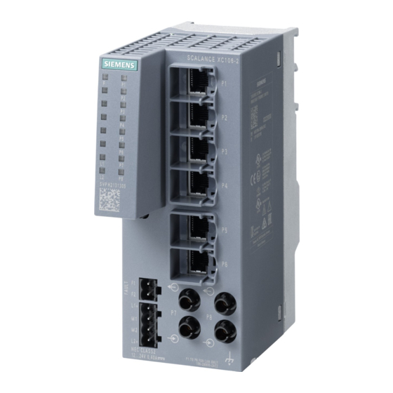
Description of the device 3.2 Device views Device views 3.2.1 Device view of a SCALANCE XC106-2 (SC) The following figure shows an overview of the components of the SCALANCE XC106-2 (SC). ① Electrical ports ② Optical ports (SC) ③ Grounding screw ④... -
Page 14: Device View Of A Scalance Xc106-2 (St/Bfoc)
Description of the device 3.2 Device views 3.2.2 Device view of a SCALANCE XC106-2 (ST/BFOC) The following figure shows an overview of the components of the SCALANCE XC106-2 (ST/ BFOC). ① Electrical ports ② Optical ports (ST/BFOC) ③ Grounding screw ④... -
Page 15: Device View Of A Scalance Xc108
Description of the device 3.2 Device views 3.2.3 Device view of a SCALANCE XC108 The following figure shows an overview of the components of the SCALANCE XC108. ① Electrical ports ② Grounding screw ③ Knurled screw ④ Securing bar ⑤ Levering aid for moving the securing bar with a screwdriver ⑥... -
Page 16: Device View Of A Scalance Xc116
Description of the device 3.2 Device views 3.2.4 Device view of a SCALANCE XC116 The following figure shows an overview of the components of the SCALANCE XC116. ① Electrical ports ② Grounding screw ③ Knurled screw ④ Securing bar ⑤ Levering aid for moving the securing bar with a screwdriver ⑥... -
Page 17: Device View Of A Scalance Xc124
Description of the device 3.2 Device views 3.2.5 Device view of a SCALANCE XC124 The following figure shows an overview of the components of the SCALANCE XC124. ① Electrical ports ② Grounding screw ③ Knurled screw ④ Securing bar ⑤ Levering aid for moving the securing bar with a screwdriver ⑥... -
Page 18: Led Display
Description of the device 3.3 LED display LED display Fault LED "F" (red LED) The fault LED indicates the incorrect functioning of the device. LED color LED status Meaning The IE switch detects an error. At the same time, the signaling contact opens. The following faults/errors are detected: 1. -
Page 19: Set Button
Description of the device 3.4 SET button SET button Position The "SET" button is located on the front of the device. Figure 3-1 Position of the "SET" button Function With the SET button, you can display and change the set fault mask. Setting the fault mask Factory setting In its delivery condition (factory default), the following settings are monitored via the message... - Page 20 Description of the device 3.4 SET button Phase Description LEDs flash at 5 Hz The currently set fault mask is displayed. The LEDs of the monitored ports flash. If no fault mask is set, all port LEDs flash one after the other. If you release the button in phase 1, this has no effect.
-
Page 21: Installation And Disassembly
Installation and disassembly Safety notices for installation Safety notices When installing the device, keep to the safety notices listed below. WARNING If a device is operated in an ambient temperature of more than 60 °C, the temperature of the device housing may be higher than 70 °C. The device must therefore be installed so that it is only accessible to service personnel or users that are aware of the reason for restricted access and the required safety measures at an ambient temperature higher than 60 °C. - Page 22 Installation and disassembly 4.1 Safety notices for installation Safety notices on use in hazardous areas General safety notices relating to protection against explosion WARNING EXPLOSION HAZARD Replacing components may impair suitability for Class 1, Division 2 or Zone 2. WARNING The device is intended for indoor use only.
- Page 23 Installation and disassembly 4.1 Safety notices for installation WARNING EXPLOSION HAZARD For operation the device is intended to be installed within an enclosure/control cabinet. The inner temperature of the enclosure/control cabinet corresponds to the ambient temperature of the device. Use installation wiring connections with admitted maximum operating temperature of at least 30 °C higher than maximum ambient temperature.
-
Page 24: Types Of Installation
Installation and disassembly 4.3 Mounting on DIN rails Types of installation Types of installation The device can be installed in the following ways: • DIN rail • S7-300 mounting rail • S7-1500 mounting rail • Wall mounting Installation clearance Keep to the minimum clearances so that the convection ventilation of the device is not blocked. •... -
Page 25: Installation On A Standard S7-300 Rail
Installation and disassembly 4.4 Installation on a standard S7-300 rail Securing bar in the wall mounting position (as supplied). To install the device on a 35 mm DIN rail complying with DIN EN 60715, follow the steps below: 1. Loosen the knurled screw with your hand or a screwdriver. 2. - Page 26 Installation and disassembly 4.4 Installation on a standard S7-300 rail Figure 4-2 S7-300 mounting rail installation with the securing bar in the wall mounting position. Securing bar in the wall mounting position (as supplied). To install the device on an S7-300 standard rail, follow the steps below: 1.
-
Page 27: Installation On A Standard S7-1500 Rail
Installation and disassembly 4.5 Installation on a standard S7-1500 rail Installation on a standard S7-1500 rail Installing on an S7-1500 standard rail Note Note the position of the securing bar, see also section “Dimension drawings (Page 49)“. When supplied, the securing bar is in the wall mounting position. To change the position of the securing bar, refer to the section “Changing the position of the securing bar (Page 29)“. -
Page 28: Wall Mounting
Installation and disassembly 4.6 Wall mounting Wall mounting Preparation Note the position of the securing bar, see also section “Dimension drawings (Page 49)“. When supplied, the securing bar is in the wall mounting position. You do not need to prepare the device any further. -
Page 29: Changing The Position Of The Securing Bar
Installation and disassembly 4.7 Changing the position of the securing bar Changing the position of the securing bar Rail mounting position - wall mounting position To change the securing bar from the rail mounting position to the wall mounting position follow the steps below: 1. -
Page 30: Disassembly
Installation and disassembly 4.8 Disassembly Disassembly WARNING Improper disassembly Improper disassembly may result in a risk of explosion in hazardous areas. For proper disassembly, observe the following: • Before starting work, ensure that the electricity is switched off. • Secure remaining connections so that no damage can occur as a result of disassembly if the system is accidentally started up. -
Page 31: Connecting Up
Connecting up Safety when connecting up Safety notices When connecting up the device, keep to the safety notices listed below. WARNING Power supply The device is designed for operation with a directly connectable safety extra low voltage (SELV) from a limited power source (LPS). The power supply therefore needs to meet at least one of the following conditions: •... - Page 32 Connecting up 5.1 Safety when connecting up Safety notices on use in hazardous areas General safety notices relating to protection against explosion WARNING EXPLOSION HAZARD Do not connect or disconnect cables to or from the device when a flammable or combustible atmosphere is present.
- Page 33 Connecting up 5.1 Safety when connecting up WARNING Unprotected cable ends There is a risk of explosion due to unprotected cable ends in hazardous areas. • Protect unused cable ends according to IEC/EN 60079-14. WARNING Improper installation of shielded cables There is a risk of explosion due to equalizing currents between the hazardous area and the non- hazardous area.
-
Page 34: Wiring Rules
Connecting up 5.2 Wiring rules WARNING EXPLOSION HAZARD You may only connect or disconnect cables carrying electricity when the power supply is switched off or when the device is in an area without inflammable gas concentrations. Further notes WARNING Safety notice for connecting with a LAN ID (Local Area Network) A LAN or LAN segment with all the interconnected devices should be contained completely in a single low voltage power distribution in a building. -
Page 35: Power Supply
Connecting up 5.3 Power supply Note Wire end ferrules Use crimp shapes with smooth surfaces, such as provided by square and trapeze shaped crimp cross sections. Crimp shapes with wave-shaped profile are unsuitable. Power supply Notes on the power supply WARNING Incorrect power supply Never operate the device with AC voltage or DC voltage higher than 32 V DC. -
Page 36: Signaling Contact
Connecting up 5.4 Signaling contact • The power supply is connected over a high resistance with the enclosure to allow an ungrounded set up. The two power inputs are non-floating. • Note the wiring rules. Position and assignment Figure 5-1 Position of the power supply on the SCALANCE XC-100 and the assignment of the terminal block Contact... -
Page 37: Functional Ground
Connecting up 5.5 Functional ground Position and assignment Figure 5-2 Position of the signaling contact on the SCALANCE XC-100 and the assignment of the terminal block Contact Assignment Fault contact 1 Fault contact 2 Signaling faults • The signaling of errors by the signaling contact is synchronized with the fault LED "F", see section "LED display (Page 18)". - Page 38 Connecting up 5.5 Functional ground ① Grounding terminal with cable ② Fillister head screw with spring washer and washer 1. Loosen the grounding screw). 2. Put the grounding terminal and grounding screw together. 3. Tighten the grounding screw with a maximum torque of 0.75 Nm. Protective/functional ground The connection of the reference potential surface with the protective ground system is normally in the cabinet close to the power feed-in.
-
Page 39: Maintenance And Troubleshooting
Maintenance and troubleshooting WARNING Unauthorized repair of devices in explosion-proof design Risk of explosion in hazardous areas • Repair work may only be performed by personnel authorized by Siemens. WARNING Impermissible accessories and spare parts Risk of explosion in hazardous areas •... - Page 40 If only the receive direction is plugged in, a “far end fault” is detected and no data is forwarded. The port LED is already lit. Device defective If a fault develops, send the device to your SIEMENS service center for repair. Repairs on-site are not possible. SCALANCE XC-100...
-
Page 41: Technical Specifications
Technical specifications Technical specifications of the SCALANCE XC106-2 (SC) The following technical specifications apply to the SCALANCE XC106-2 (SC). Technical specifications Electrical data Power supply Rated voltage 12 to 24 VDC Voltage range (incl. tolerance) 9.6 to 31.2 VDC Safe Extra Low Voltage (SELV) Design Terminal block, 4 terminals Properties... - Page 42 Technical specifications 7.1 Technical specifications of the SCALANCE XC106-2 (SC) Attachment to Industrial Ethernet Electrical connectors Properties Quantity Connector RJ-45 jack Properties Half/full duplex, MDI‑X pinning Transmission speed 10 / 100 Mbps Optical connectors Optical connectors Quantity Connectors The attachment to Industrial Ethernet uses SC connector tech‐ nology (Subscriber Connector).
-
Page 43: Technical Specifications Of The Scalance Xc106-2 (St/Bfoc)
Technical specifications 7.2 Technical specifications of the SCALANCE XC106-2 (ST/BFOC) Technical specifications of the SCALANCE XC106-2 (ST/BFOC) The following technical specifications apply to the SCALANCE XC106-2 (ST/BFOC). Technical specifications Electrical data Power supply Rated voltage 12 to 24 VDC Voltage range (incl. tolerance) 9.6 to 31.2 VDC Safe Extra Low Voltage (SELV) Design Terminal block, 4 terminals... - Page 44 Technical specifications 7.2 Technical specifications of the SCALANCE XC106-2 (ST/BFOC) Properties Properties Half/full duplex, MDI‑X pinning Transmission speed 10 / 100 Mbps Optical connectors Optical connectors Quantity Connectors The attachment to Industrial Ethernet uses ST/ BFOC connector technology (Straight Tip/Bayonet Fiber Optic Connector).
-
Page 45: Technical Specifications Of The Scalance Xc108
Technical specifications 7.3 Technical specifications of the SCALANCE XC108 Technical specifications of the SCALANCE XC108 The following technical specifications apply to the SCALANCE XC108. Technical specifications Attachment to Industrial Ethernet Electrical connectors Quantity Connector RJ-45 jack Properties Half/full duplex, MDI‑X pinning Transmission speed 10 / 100 Mbps Electrical data... -
Page 46: Technical Specifications Of The Scalance Xc116
Technical specifications 7.4 Technical specifications of the SCALANCE XC116 Technical specifications of the SCALANCE XC116 The following technical specifications apply to the SCALANCE XC116. Technical specifications Attachment to Industrial Ethernet Electrical connectors Quantity Connector RJ-45 jack Properties Half/full duplex, MDI‑X pinning Transmission speed 10 / 100 Mbps Electrical data... -
Page 47: Technical Specifications Of The Scalance Xc124
Technical specifications 7.5 Technical specifications of the SCALANCE XC124 Technical specifications of the SCALANCE XC124 The following technical specifications apply to the SCALANCE XC124. Technical specifications Attachment to Industrial Ethernet Electrical connectors Quantity Connector RJ-45 jack Properties Half/full duplex, MDI‑X pinning Transmission speed 10 / 100 Mbps Electrical data... -
Page 48: Switching Properties
Technical specifications 7.7 Mechanical stability (in operation) Switching properties Note the following switching properties: Switching properties Aging time 45 seconds Max. number of learnable MAC addresses 2048 Response to LLDP frames Blocking Response to spanning tree BPDU frames Forwarding CoS acc. to IEEE 802.1Q QoS priority queues IEEE 802.1Q tags (VLAN ID, priority) transparent forwarding... -
Page 49: Dimension Drawings
Dimension drawings Note Dimensions are specified in mm. Front view of the SCALANCE XC106-2 (SC), SCALANCE XC106-2 (ST/BFOC), SCALANCE XC108 ① Securing bar in the rail mounting position ② Securing bar in the wall mounting position (as supplied). Figure 8-1 Width and height SCALANCE XC-100 Operating Instructions, 06/2022, C79000-G8976-C415-06... - Page 50 Dimension drawings Front view of the SCALANCE XC116, SCALANCE XC124 ① Securing bar in the rail mounting position ② Securing bar in the wall mounting position (as supplied). Figure 8-2 Width and height SCALANCE XC-100 Operating Instructions, 06/2022, C79000-G8976-C415-06...
- Page 51 Dimension drawings Side view of the SCALANCE XC-100 ① Securing bar in the rail mounting position ② Securing bar in the wall mounting position (as supplied). Figure 8-3 Depth SCALANCE XC-100 Operating Instructions, 06/2022, C79000-G8976-C415-06...
- Page 52 Dimension drawings Drilling template for wall mounting Figure 8-4 Drilling template SCALANCE XC-100 Operating Instructions, 06/2022, C79000-G8976-C415-06...
-
Page 53: Certifications And Approvals
Current approvals on the Internet You will find the current approvals for the product on the Internet pages of Siemens Industry Online Support (https://support.industry.siemens.com/cs/ww/en/ps/15273/cert). Notes for the manufacturers of machines This product is not a machine in the sense of the EC Machinery Directive or the Supply of Machinery (Safety) Regulations (UK). - Page 54 Process Automation DE-76181 Karlsruhe Germany Importer UK: Siemens plc, Manchester M20 2UR You can find the current UK Declaration of Conformity for these products on the Internet pages under Siemens Industry Online Support (https://support.industry.siemens.com/cs/ww/en/ps/ 15273/cert). SCALANCE XC-100 Operating Instructions, 06/2022, C79000-G8976-C415-06...
- Page 55 "SIMATIC NET Product Information Use of subassemblies/modules in a Zone 2 Hazardous Area". You will find this document • on the data medium that ships with some devices. • on the Internet pages under Siemens Industry Online Support (https:// support.industry.siemens.com/cs/ww/en/view/78381013).
- Page 56 Certifications and approvals You will find the current versions of the standards in the currently valid certificates. Note for devices with CLASS 1 LASER Important note on products certified according to Type Examination Certificate KEMA 07ATEX0145 X as of Issue 95 / DEKRA 18ATEX0025 X and IECEx Certificate of Conformity DEK 14.0025X as of Issue 43 / DEK 18.0017X and containing Class 1 optical radiation sources.
- Page 57 Certifications and approvals cULus approval for industrial control equipment cULus Listed IND. CONT. EQ. Underwriters Laboratories Inc. complying with • UL 61010-2-201 • CAN/CSA-IEC 61010-2-201 Report no. E85972 cULus Approval for Information Technology Equipment cULus Listed I. T. E. Underwriters Laboratories Inc. complying with •...
- Page 58 Certifications and approvals Note for Australia - RCM The product meets the requirements of the RCM standard. Applied standards: • AS/NZS CISPR11 (Industrial, scientific and medical equipment - Radio-frequency disturbance characteristics - Limits and methods of measurement). • EN 61000-6-4 Electromagnetic compatibility (EMC) - Part 6-4: Generic standards - Emission standard for industrial environments You will find the current versions of the standards in the currently valid RCM SDoCs (Self- Declaration of Conformity).
- Page 59 • "Industrial Ethernet / PROFINET Industrial Ethernet" System Manual (https:// support.industry.siemens.com/cs/ww/en/view/27069465) • "Industrial Ethernet / PROFINET - Passive Network Components" System Manual (https:// support.industry.siemens.com/cs/ww/en/view/84922825) • "EMC Installation Guidelines" configuration manual (https:// support.industry.siemens.com/cs/ww/en/view/60612658)
- Page 60 Certifications and approvals SCALANCE XC-100 Operating Instructions, 06/2022, C79000-G8976-C415-06...
-
Page 61: Index
Index Ambient temperature, 41, 43, 45, 46, 47 Installation, 41, 43, 45, 46, 47 Approvals, 53 Installation on a DIN rail, 25 Article numbers, 11 Installation on a standard rail, 26, 27 Attachment to Industrial Ethernet, 45, 46, 47 Wall mounting, 28 Installation on a DIN rail, 25 Installation on a standard rail, 26, 27 CE mark, 53... - Page 62 Index SIMATIC NET glossary, 6 SIMATIC NET manual, 6 Spare parts, 12 Spring-loaded terminal, 11, 35, 36 System manual, 6, 59 Weight, 41, 43, 45, 46, 47 SCALANCE XC-100 Operating Instructions, 06/2022, C79000-G8976-C415-06...