Table of Contents
Advertisement
Quick Links
SERVICE MANUAL
Ver 1.0 2000. 12
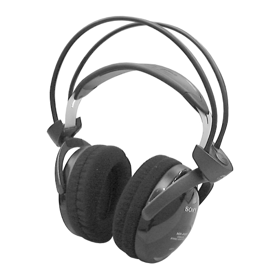
MDR-IF630R is the component model block one in the MDR-IF630RK.
COMPONENT MODEL NAME FOR MDR-IF630RK
Headphones
MDR-IF630R
Transmitter
TMR-IF630R
MDR-IF630R
SPECIFICATIONS
Headphones
Type
Closed, dynamic
Driver unit
30 mm dia. with neodymium
magnet
Frequency response
12 – 24,000 Hz
Power source
DC 2.4 V: Built-in rechargeable
batteries
Mass
Approx. 310 g (10.9 oz)
Built-in rechargeable batteries
Model name
NH-AAC
Type
Ni-MH
Voltage
1.2 V
Capacity
1000 mAh
Design and specifications are subject to change without
notice.
US Model
AEP Model
UK Model
E Model
Tourist Model
HEADPHONES
Advertisement
Table of Contents

Summary of Contents for Sony MDR-IF630R
- Page 1 MDR-IF630R SERVICE MANUAL US Model AEP Model Ver 1.0 2000. 12 UK Model E Model Tourist Model MDR-IF630R is the component model block one in the MDR-IF630RK. COMPONENT MODEL NAME FOR MDR-IF630RK Headphones MDR-IF630R Transmitter TMR-IF630R SPECIFICATIONS Headphones Type Closed, dynamic Driver unit 30 mm dia.
-
Page 2: Section 1 General
SECTION 1 This section is extracted from instruction manual. GENERAL Check the remaining power of the headphone batteries Pull up the suspender, and check that the headphones’ power indicator lights in red. You can now use the headphones. Charge the batteries or install new batteries, if the power indicator light is weak or turned off and the sound become distorted or has a lot of noise. -
Page 3: Section 2 Disassembly
SECTION 2 DISASSEMBLY • The equipment can be removed using the following procedure. Lid (R), holder Hanger (R) RX SW board, Holder (R) Driver (R side) RX BASE board Driver (L side) RX CHR board Lid (L), holder Hanger (L) Holder (L) Note : Follow the disassembly procedure in the numerical order given. - Page 4 2-3. LID (R), HOLDER 4 Lid (R), holder 2 Housing (R) assy 3 Two screws (+P2 × 6) 6 Claw 2-4. HANGER (R) Precaution for installation Solder the each lead wires directly to the position as shown while being cautions of colors Groove HANGER (R) Hanger (R)
- Page 5 2-5. RX SW BOARD, HOLDER (R) 3 Head band (rear) 2 Head band (front) q; Cushion assy, head Holder (R) 6 Two springs 8 Remove the two solderings 1 Two screws (+P2 × 2.5) RX SW board 5 Chassis Natural 4 Screw (+P2 ×...
- Page 6 2-7. RX CHR BOARD Precaution for installation 5 Terminal (–), battery Solder the each lead wires directly to the position as shown while being cautions of colors 4 Two terminals, charge 7 Screw RX CHR board (+P2 × 6) Terminal (–), battery Head band (front) (natural) Head band (front) (black) Box assy, battery...
- Page 7 2-9. HANGER (L) Precaution for installation Solder the each lead wires directly to the position as shown while being cautions of colors Hanger (L) Groove Hanger (L) Groove Groove Groove From head band (rear) Groove Groove Lid (L), hanger From head band (front) 2-10.
-
Page 8: Section 3 Electrical Adjustments
¶ Supply 9 V dc to the transmitter section (TMR-IF630R) and 2.4 V dc to the headphones section (MDR-IF630R) as the power voltage. Feed a signal to jig (TMR-IF630R) and connect a power supply to DC IN jack (J4). - Page 9 MDR-IF630R SECTION 4 DIAGRAMS 4-1. BLOCK DIAGRAM L203 2.3 MHz B.P.F L204 2.3MHz DET. COIL SW301(1/2) RV301(1/2) SOUND MODE VOICE IC202 IC203 IC204 EXPANDER VOICE ENHANCER MIXER LIMITER QUAD COIL IC301(1/2) POWER AMP D301, SENSOR) AMP. NORMAL D302 Q301-Q303 Q304...
- Page 10 MDR-IF630R • See page 15 for IC Block Diagrams. 4-2. SCHEMATIC DIAGRAM SOUND MODE VOICE NORMAL • Waveforms IC101 3 600 mVp-p 358 nsec VOLT/DIV : 200 mV TIME/DIV : 200 ns IC201 3 636 mVp-p 434 nsec VOLT/DIV : 200 mV...
- Page 11 MDR-IF630R 4-3. PRINTED WIRING BOARD • Semiconductor Location Ref. No. Location D101 (IR SENSOR) D102 D301 D302 D305 IC101 IC102 IC103 IC104 (POWER) IC201 SW– 1-679-551 IC202 IC203 IC204 (11) IC301 Q101 Q201 IC101 Q301 IC201 Q302 Q303 Q304 (IR SENSOR)
- Page 12 • IC BLOCK DIAGRAMS IC101, IC201 SC111711DR2 MIXER SCAN SQUELCH FILTER FILTER RECOVERD INPUT MUTE CONTROL OUTPUT INPUT AUDIO – FILTER SQUELCH TRIGGER WITH HYSTERESIS DEMODULATOR MIXER LIMITER OSCILLATOR MIXER LIMITER QUAD OUTPUT INPUT COIL CRYSTAL DECOUPLING IC104, IC204 MC34119DTBR2 BIAS CIRCUIT —...
-
Page 13: Section 5 Exploded Views
SECTION 5 EXPLODED VIEWS NOTE: • -XX, -X mean standardized parts, so they may • The mechanical parts with no reference number have some differences from the original one. in the exploded views are not supplied. • Items marked “*” are not stocked since they •... -
Page 14: Section 6 Electrical Parts List
SECTION 6 RX BASE ELECTRICAL PARTS LIST NOTE: • Due to standardization, replacements in the • CAPACITORS: • SEMICONDUCTORS parts list may be different from the parts uF: µF In each case, u: µ, for example: specified in the diagrams or the components •... - Page 15 RX BASE Ref. No. Part No. Description Remarks Ref. No. Part No. Description Remarks < IC > R115 1-216-818-11 METAL CHIP 1/16W R116 1-216-833-11 METAL CHIP 1/16W IC101 8-759-473-72 IC SC111711DR2 R117 1-216-824-11 METAL CHIP 1.8K 1/16W IC102 8-759-384-90 IC TK10691MTL IC103 8-759-344-00 IC NJM2100E(TE2) R118...
- Page 16 RX CHR RX SW Ref. No. Part No. Description Remarks 1-679-553-11 RX CHR BOARD ************* 3-222-514-01 TERMINAL, CHARGE 3-222-516-01 TERMINAL (+), BATTERY 3-223-778-01 TERMINAL (-), BATTERY < DIODE > D303 8-719-058-49 DIODE PP508 (IR SENSOR) D304 8-719-058-49 DIODE PP508 (IR SENSOR) D306 8-719-975-40 DIODE RB411D <...
- Page 17 MDR-IF630R Sony Corporation 2000L16023-1 Audio Entertainment Group 9-873-017-11 Printed in Japan © 2000.12 — 20 — Published by General Engineering Dept.


