Advertisement
Table of Contents
Advertisement
Chapters
Table of Contents

Related Manuals for Toro 39901


Summary of Contents for Toro 39901
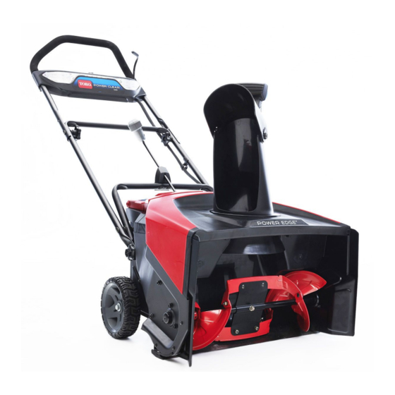
- Page 1 Form No. 3438-775 Rev A 60V MAX e21 Power Clear® Snow Thrower with Flex—Force Power System® Service Manual Published: May 2020 © 2020—The Toro® Company Original Instructions (EN) 8111 Lyndale Avenue South Contact us at www.Toro.com. Bloomington, MN 55420 All Rights Reserved...
- Page 2 Revision History Revision History Page 2 60V MAX e21 Power Clear® Snow Thrower with Flex—Force Power System® Service Manual 3438-775 Rev A...
- Page 3 The Toro Company RLC/SWS Customer Care Department 8111 Lyndale Avenue South Bloomington, MN 55420 The Toro Company reserves the right to change product specifications or make changes to this manual without notice. 60V MAX e21 Power Clear® Snow Thrower Page 3 Preface with Flex—Force Power System®...
- Page 4 Service Procedure Icons The following icons appear throughout this Service Manual to bring attention to specific important details of a service procedure. Critical Process This icon is used to highlight: • Installing safety equipment (shields, guards, seat belts, brakes, and R.O.P.S. components) that may have been removed •...
- Page 5 Table of Contents Preface ........................ 3 Chapter 1: Safety .................... 1–1 Safety Instructions ..................1–2 Chapter 2: Specifications and Maintenance ............ 2–1 Specifications ....................2–2 Torque Specifications ................... 2–3 Chapter 3: Troubleshooting ................3–1 General Troubleshooting ................3–4 Chapter 4: Battery ..................4–1 General Information ..................
- Page 6 Preface Page 6 60V MAX e21 Power Clear® Snow Thrower with Flex—Force Power System® Service Manual 3438-775 Rev A...
- Page 7 Chapter 1 Safety Table of Contents Safety Instructions ..........................1–2 Think Safety First ..........................1–2 60V MAX e21 Power Clear® Snow Thrower with Page 1–1 Safety Flex—Force Power System® Service Manual 3438-775 Rev A...
- Page 8 Safety Instructions DANGER This safety symbol means danger. When you see this symbol, carefully read the instructions that follow. Failure to obey the instructions could cause serious permanent injury, disability, or death. WARNING This safety symbol means warning. When you see this symbol, carefully read the instructions that follow.
- Page 9 Think Safety First (continued) Battery acid is poisonous and can cause burns. Avoid contact with skin, eyes and clothing. Battery gases can explode. Keep cigarettes, sparks and flames away from the battery. Avoid injury due to inferior parts… Use only original equipment parts to ensure that important safety criteria are met. Avoid injury to bystanders…...
- Page 10 Think Safety First (continued) The proper class of fire extinguisher should be used in case of fire. Class A extinguishers are for ordinary combustible materials such as paper, wood, cardboard, and most plastics. The numerical rating on these types of extinguishers indicates the amount of water it holds and the amount of fire it can extinguish.
- Page 11 Chapter 2 Specifications and Maintenance Table of Contents Specifications ............................2–2 Torque Specifications ........................... 2–3 Equivalents and Conversions......................2–8 U.S. to Metric Conversions ........................ 2–9 60V MAX e21 Power Clear® Snow Thrower with Page 2–1 Specifications and Maintenance Flex—Force Power System® Service Manual 3438-775 Rev A...
- Page 12 Specifications 60V MAX e21 Power Clear® Snow Thrower with Flex—Force Power System® Model 39901/39902 Throw Distance Up to 12 m (40 ft) Clearing Width 53 cm (21 inches) Weight 27.2 kg (60 lb) Length 145 cm (57 inches) Width 53 cm (21 inches) Height 72 cm (28.5 inches)
- Page 13 Torque Specifications The recommended fastener torque values are listed in the following tables. For critical applications, as determined by Toro, either the recommended torque or a torque that is unique to the application is clearly identified and specified in the service manual.
- Page 14 Metric Bolts and Screws g272209 Figure 2 Class 8.8 Class 10.9 Specifications and Maintenance: Torque Specifications Page 2–4 60V MAX e21 Power Clear® Snow Thrower with Flex—Force Power System® Service Manual 3438-775 Rev A...
- Page 15 Standard Torque for Dry, Zinc Plated, and Steel Fasteners (Inch Series) Thread Size Grade 1, SAE Grade 1 Bolts, Screws, SAE Grade 5 Bolts, Screws, SAE Grade 8 Bolts, Screws, 5, & 8 Studes & Sems with Studs & Sems with Regular Studs &...
- Page 16 Standard Torque for Dry, Zinc Plated, and Steel Fasteners (Metric Series) Thread Size Class 8.8 Bolts, Screws, Studs with Regular Class 10.9 Bolts, Screws, Studs with Regular Height Nuts (Class 8 or Stronger Nuts) Height Nuts (Class 10 or stronger Nuts) in-lb N •...
- Page 17 SAE Grade 8 Steel Set Screws Recommended Torque Thread Size Square Head Hex Socket 1/4 - 20 UNC 140 ± 20 in-lb 73 ± 12 in-lb 5/16 - 18 UNC 215 ± 35 in-lb 145 ± 20 in-lb 1/2 - 13 UNC 75 ±...
- Page 18 Equivalents and Conversions Decimal and Millimeter Equivalents Fractions Decimals Fractions Decimals 1/64 0.015625 0.397 33/64 0.515625 13.097 1/32 0.03125 0.794 16/32 0.53125 13.484 3/64 0.046875 1.191 35/64 0.546875 13.891 1/16 0.0625 1.588 9/16 0.5625 14.288 5/64 0.078125 1.984 37/64 0.578125 14.684 3/32 0.9375...
- Page 19 U.S. to Metric Conversions To Convert Into Multiply By Miles Kilometers 1.609 Yards Meters 0.9144 Feet Meters 0.3048 Linear Measurement Feet Centimeters 30.48 Inches Meters 0.0254 Inches Centimeters 2.54 Inches Millimeters 25.4 Square Miles Square Kilometers 2.59 Square Feet Square Meters 0.0929 Area Square Inches...
- Page 20 Specifications and Maintenance: Torque Specifications Page 2–10 60V MAX e21 Power Clear® Snow Thrower with Flex—Force Power System® Service Manual 3438-775 Rev A...
- Page 21 Chapter 3 Troubleshooting Table of Contents General Troubleshooting ........................3–4 60V MAX e21 Power Clear® Snow Thrower with Page 3–1 Troubleshooting Flex—Force Power System® Service Manual 3438-775 Rev A...
- Page 22 GEARS The Systematic approach to defining, diagnosing and solving problems. Gather Information • Information reported by the customer • Information observed by you • Establish the what, where and when of the issue Evaluate Potential Causes • Consider possible causes of the problem to develop a hypothesis •...
- Page 23 Error Beep Table Error Type Number of Beeps Next Step Communication Error Verify motor driver and battery functionality. Replace motor driver and/or battery as necessary. Time Out Error Verify motor driver and battery functionality. Replace motor driver and/or battery as necessary.
- Page 24 General Troubleshooting See Operator’s Manual for troubleshooting information. Troubleshooting: General Troubleshooting Page 3–4 60V MAX e21 Power Clear® Snow Thrower with Flex—Force Power System® Service Manual 3438-775 Rev A...
- Page 25 Chapter 4 Battery Table of Contents General Information ..........................4–2 Service and Repairs ..........................4–3 Battery Track Assembly Replacement ....................4–4 60V MAX e21 Power Clear® Snow Thrower with Page 4–1 Battery Flex—Force Power System® Service Manual 3438-775 Rev A...
- Page 26 General Information This is a 60 volt MAX snowthrower. Battery: General Information Page 4–2 60V MAX e21 Power Clear® Snow Thrower with Flex—Force Power System® Service Manual 3438-775 Rev A...
- Page 27 Service and Repairs Battery Track Assembly g320492 Figure 3 Battery Container Skirt 60v Charger Battery Track Assembly Battery Container 60V MAX e21 Power Clear® Snow Thrower with Page 4–3 Battery: Service and Repairs Flex—Force Power System® Service Manual 3438-775 Rev A...
- Page 28 Battery Track Assembly Replacement Battery Track Assembly Removal 1. Park the machine on a level surface and wait for all moving parts to stop. WARNING When removing or installing the battery, do not allow the battery terminals to touch any metal parts of the machine. Do not allow metal tools to short between the battery terminals and metal parts of the machine.
- Page 29 Battery Track Assembly Removal (continued) g320276 Figure 5 8. Remove the 3 screws securing the battery container skirt to the battery container. Remove the battery container skirt from the machine. g320289 Figure 6 9. Flip the machine over so the auger housing is facing the floor. Remove the 2 screws securing the battery track assembly to the battery container.
- Page 30 Battery Track Assembly Removal (continued) g320309 Figure 7 10. Flip the machine over so the wheels are on the ground. Remove the 2 screws securing the battery track assembly to the battery container. Remove the battery track assembly from the battery container skirt. g320308 Figure 8 Battery Track Assembly Installation...
- Page 31 Battery Track Assembly Installation (continued) g320308 Figure 9 2. Flip the machine over so the auger housing is facing the floor. Install the 2 screws securing the battery track assembly to the frame. Torque the screws to 1.1-1.7 N • m (10-15 in-lb). g320309 Figure 10 3.
- Page 32 Battery Track Assembly Installation (continued) g320289 Figure 11 4. Install the 2 screws securing the battery container skirt to the battery container. Torque the screws to 1.1-1.7 N • m (10-15 in-lb). g320276 Figure 12 5. Connect all the wire attachments to the motor driver. 6.
- Page 33 Battery Track Assembly Installation (continued) g320303 Figure 13 7. Install the 2 screws securing the controller cover to the battery container skirt. Torque the screws to 1.1-1.7 N • m (10-15 in-lb). 8. Install the chute control rod into the machine. WARNING When removing or installing the battery, do not allow the battery terminals to touch any metal parts of the machine.
- Page 34 Battery: Service and Repairs Page 4–10 60V MAX e21 Power Clear® Snow Thrower with Flex—Force Power System® Service Manual 3438-775 Rev A...
- Page 35 Chapter 5 Drive System Table of Contents General Information ..........................5–2 Service and Repairs ..........................5–3 Ribbed V-Belt Replacement ....................... 5–4 Rotor Replacement ..........................5–6 60V MAX e21 Power Clear® Snow Thrower with Page 5–1 Drive System Flex—Force Power System® Service Manual 3438-775 Rev A...
-
Page 36: General Information
General Information This is a free wheeling snowthrower with no drive assist. Drive System: General Information Page 5–2 60V MAX e21 Power Clear® Snow Thrower with Flex—Force Power System® Service Manual 3438-775 Rev A... -
Page 37: Service And Repairs
Service and Repairs Rotor Assembly g320450 Figure 14 RH Sideplate Cap LH Extension Ball Bearing Ribbed Belt RH Extension Rotor Pulley Asm Rotor Belleville Washer 60V MAX e21 Power Clear® Snow Thrower with Page 5–3 Drive System: Service and Repairs Flex—Force Power System®... -
Page 38: Ribbed V-Belt Replacement
Ribbed V-Belt Replacement Ribbed V-Belt Removal 1. Park the machine on a level surface and wait for all moving parts to stop. WARNING When removing or installing the battery, do not allow the battery terminals to touch any metal parts of the machine. Do not allow metal tools to short between the battery terminals and metal parts of the machine. - Page 39 Ribbed V-Belt Removal (continued) 5. Remove the rotor pulley assembly from the rotor shaft. g320312 Figure 17 6. Remove ribbed V-belt from the rotor pulley assembly and the motor pulley. Ribbed V-Belt Installation 1. Install the rotor pulley assembly onto the rotor shaft. Install the Belleville washer and new screw securing the rotor pulley assembly to the rotor shaft.
-
Page 40: Rotor Replacement
Ribbed V-Belt Installation (continued) g320499 Figure 18 Plastic Screw Screws WARNING When removing or installing the battery, do not allow the battery terminals to touch any metal parts of the machine. Do not allow metal tools to short between the battery terminals and metal parts of the machine. - Page 41 Rotor Removal (continued) g320292 Figure 19 5. Remove the 2 screw securing the LH frame plate to the housing g320272 Figure 20 6. Remove the 3 screws securing the RH frame plate to the housing and the RH extension. 60V MAX e21 Power Clear® Snow Thrower with Page 5–7 Drive System: Service and Repairs Flex—Force Power System®...
- Page 42 Rotor Removal (continued) g320293 Figure 21 7. Remove the 3 screws securing the RH frame plate to the housing. g320294 Figure 22 8. Remove the 2 screws securing the RH frame plate to the housing. Drive System: Service and Repairs Page 5–8 60V MAX e21 Power Clear®...
- Page 43 Rotor Removal (continued) g320274 Figure 23 9. Slide and remove the rotor assembly from the housing. g321114 Figure 24 Rotor Installation 1. Slide and install the rotor assembly to the housing. 2. Install the 2 screws securing the RH frame plate to the housing. Torque the screws to 2.8–4 N •...
- Page 44 Rotor Installation (continued) g320274 Figure 25 3. Install the 3 screws securing the RH frame plate to the housing. Torque the screws to 2.3–2.8 N • m (20–25 in-lb). g320294 Figure 26 Drive System: Service and Repairs Page 5–10 60V MAX e21 Power Clear® Snow Thrower with Flex—Force Power System®...
- Page 45 Rotor Installation (continued) 4. Install the 3 screws securing the RH frame plate to the housing and RH extension. Torque the screws to 5–6.8 N • m (45–60 in-lb). g320293 Figure 27 5. Install the 2 screw securing the LH frame plate to the housing. Torque the screws to 2.8–4 N •...
- Page 46 Rotor Installation (continued) g320292 Figure 29 7. Install the ribbed V-belt. Ribbed V-Belt Installation (page 5–5) WARNING When removing or installing the battery, do not allow the battery terminals to touch any metal parts of the machine. Do not allow metal tools to short between the battery terminals and metal parts of the machine.
- Page 47 Chapter 6 Chute Table of Contents General Information ..........................6–2 Service and Repairs ..........................6–3 Chute Gear Replacement ........................6–4 Chute Replacement ......................... 6–14 60V MAX e21 Power Clear® Snow Thrower with Page 6–1 Chute Flex—Force Power System® Service Manual 3438-775 Rev A...
-
Page 48: General Information
General Information This snowthrower is equipped with a manual rotation chute and throw distance selection. Chute: General Information Page 6–2 60V MAX e21 Power Clear® Snow Thrower with Flex—Force Power System® Service Manual 3438-775 Rev A... -
Page 49: Service And Repairs
Service and Repairs Chute Assembly g320445 Figure 30 Battery Cover Chute Gear Chute Rear Chute Shroud Sector Gear Controller Cover Plastic Screw Gear Bracket Belt Cover 60V MAX e21 Power Clear® Snow Thrower with Page 6–3 Chute: Service and Repairs Flex—Force Power System®... -
Page 50: Chute Gear Replacement
Chute Gear Replacement Chute Gear Removal 1. Park the machine on a level surface and wait for all moving parts to stop. WARNING When removing or installing the battery, do not allow the battery terminals to touch any metal parts of the machine. Do not allow metal tools to short between the battery terminals and metal parts of the machine. - Page 51 Chute Gear Removal (continued) g320276 Figure 32 8. Remove the 3 screws securing the battery container skirt to the battery container. Remove the battery container skirt. g320289 Figure 33 9. Remove the 4 screws and washers securing the battery container to the bulkhead.
- Page 52 Chute Gear Removal (continued) g320297 Figure 34 10. Remove the 3 screws securing the shroud to the rear chute. Remove the shroud from the rear chute. 11. Remove the 2 screws securing the LH frame assembly plate to the bulkhead. g320271 Figure 35 12.
- Page 53 Chute Gear Removal (continued) g320273 Figure 36 13. Remove the 2 screws and 2 washers securing the upper bulkhead to the upper housing. g320494 Figure 37 Screw Washer 14. Remove the 2 screws securing the lower bulkhead to the lower housing. Remove the bulkhead from the housing.
- Page 54 Chute Gear Removal (continued) g324235 Figure 38 15. Remove the 2 screws securing the gear bracket to the rear chute and the housing. g320270 Figure 39 16. Remove the gear bracket and attached sector gear from the chute gear. 17. Remove the chute gear from the rear chute. Chute Gear Installation 1.
- Page 55 Chute Gear Installation (continued) g321111 Figure 40 2. Clock the sector gear to the chute gear by aligning the middle dot of the sector gear between the two does of the chute gear. g321112 Figure 41 3. Install the 2 screws securing the gear bracket to the rear chute and housing. Torque the screws to 1.1-1.7 N •...
- Page 56 Chute Gear Installation (continued) g320270 Figure 42 4. Install the 2 screws and 2 washers securing the upper bulkhead to the upper housing. Torque the screws to 2.26–2.82 N• m (20–25 in-lb). g320494 Figure 43 Screw Washer Install the 2 screws securing the lower bulkhead to the lower housing. Torque the screws to 2.26–2.82 N•...
- Page 57 Chute Gear Installation (continued) g324235 Figure 44 6. Install the 2 screws securing the RH frame plate assembly to the bulkhead. Torque the screws to 2.26–2.82 N• m (20–25 in-lb). g320273 Figure 45 7. Install the 2 screws securing the LH frame plate assembly to the bulkhead. Torque the screws to 2.26–2.82 N•...
- Page 58 Chute Gear Installation (continued) g320271 Figure 46 8. Install the shroud onto the rear chute. Install the 3 screws securing the shroud to the rear chute. Torque the screws to 1.1-1.7 N • m (10-15 in-lb). 9. Install the battery container to the bulk head. Install the 4 screws and washers securing the battery container to the bulkhead.
- Page 59 Chute Gear Installation (continued) 10. Install the 2 screws securing the battery container skirt to the battery container. Torque the screws to 1.1-1.7 N • m (10-15 in-lb) g320276 Figure 48 11. Install the 3 screws securing the battery container skirt to the battery container.
-
Page 60: Chute Replacement
Chute Gear Installation (continued) g320303 Figure 50 14. Install the 2 screws securing the controller cover to the battery container skirt. Torque the screws to 1.1-1.7 N • m (10-15 in-lb). 15. Install the chute control rod. WARNING When removing or installing the battery, do not allow the battery terminals to touch any metal parts of the machine. - Page 61 Chute Removal (continued) g320296 Figure 51 5. Lift and remove the rear chute and chute from the housing. g321113 Figure 52 Chute Installation 1. Install the chute and rear chute onto the housing. 2. Install the 4 screws securing the rear chute to the housing. Torque the screws to 1.7–2.3 N •...
- Page 62 Chute Installation (continued) g320296 Figure 53 3. Install the chute gear. Chute Gear Installation (page 6–8) WARNING When removing or installing the battery, do not allow the battery terminals to touch any metal parts of the machine. Do not allow metal tools to short between the battery terminals and metal parts of the machine.
- Page 63 Chapter 7 Controls Table of Contents General Information ..........................7–2 Service and Repairs ..........................7–3 Dash Panel Assembly Replacement ....................7–4 60V MAX e21 Power Clear® Snow Thrower with Page 7–1 Controls Flex—Force Power System® Service Manual 3438-775 Rev A...
- Page 64 General Information This snowthrower is equipped with a push button motor start and safety switch located in the handle lever. Controls: General Information Page 7–2 60V MAX e21 Power Clear® Snow Thrower with Flex—Force Power System® Service Manual 3438-775 Rev A...
- Page 65 Service and Repairs Dash Panel Assembly g320410 Figure 54 Handle Screw Flange Nut Bail Key Chute Control Rod Dash Panel Asm 60V MAX e21 Power Clear® Snow Thrower with Page 7–3 Controls: Service and Repairs Flex—Force Power System® Service Manual 3438-775 Rev A...
- Page 66 Dash Panel Assembly Replacement Dash Panel Assembly Removal 1. Park the machine on a level surface and wait for all moving parts to stop. WARNING When removing or installing the battery, do not allow the battery terminals to touch any metal parts of the machine. Do not allow metal tools to short between the battery terminals and metal parts of the machine.
- Page 67 Dash Panel Assembly Removal (continued) g320304 Figure 56 6. Remove the screw securing battery container skirt to the battery container. g320521 Figure 57 60V MAX e21 Power Clear® Snow Thrower with Page 7–5 Controls: Service and Repairs Flex—Force Power System® Service Manual 3438-775 Rev A...
- Page 68 Dash Panel Assembly Removal (continued) 7. Remove the harness from the battery container. g320305 Figure 58 8. Remove the 5 screws securing the front and rear dash panels. g320298 Figure 59 9. Remove the 4 flange nuts and 4 handle screws securing the front and rear dash panels onto the upper handle assembly.
- Page 69 Dash Panel Assembly Removal (continued) g320295 Figure 60 10. Separate the front and rear dash panels from the upper handle assembly. Dash Panel Assembly Installation 1. Position the front and rear dash panels onto the upper handle assembly. 2. Install the 4 nuts and 4 handle screws securing the front and rear dash panels onto the upper handle.
- Page 70 Dash Panel Assembly Installation (continued) g320298 Figure 62 4. Route the harness through the battery container. 5. Install the screw securing battery container skirt to the battery container. Torque the screw to 1.1-1.7 N • m (10-15 in-lb). g320521 Figure 63 Controls: Service and Repairs Page 7–8 60V MAX e21 Power Clear®...
- Page 71 Dash Panel Assembly Installation (continued) 6. Connect the harness to the motor driver. g320304 Figure 64 7. Install the 4 screws securing the motor driver to the battery container skirt. Torque the screws to 1.1-1.7 N • m (10-15 in-lb). g320303 Figure 65 8.
- Page 72 Dash Panel Assembly Installation (continued) WARNING When removing or installing the battery, do not allow the battery terminals to touch any metal parts of the machine. Do not allow metal tools to short between the battery terminals and metal parts of the machine.
- Page 73 Chapter 8 Motor Table of Contents General Information ..........................8–2 Service and Repairs ..........................8–3 Motor Driver Replacement ......................... 8–4 Motor Replacement..........................8–5 60V MAX e21 Power Clear® Snow Thrower with Page 8–1 Motor Flex—Force Power System® Service Manual 3438-775 Rev A...
-
Page 74: General Information
General Information This snowthrower comes with a pulley installed and a 60 volt motor. The 60 volt motor is not serviceable. Motor: General Information Page 8–2 60V MAX e21 Power Clear® Snow Thrower with Flex—Force Power System® Service Manual 3438-775 Rev A... -
Page 75: Service And Repairs
Service and Repairs Motor and Motor Driver Assembly g320493 Figure 66 Motor Driver Motor Pulley 60v Snowblower Motor 60V MAX e21 Power Clear® Snow Thrower with Page 8–3 Motor: Service and Repairs Flex—Force Power System® Service Manual 3438-775 Rev A... -
Page 76: Motor Driver Replacement
Motor Driver Replacement Motor Driver Removal 1. Park the machine on a level surface and wait for all moving parts to stop. WARNING When removing or installing the battery, do not allow the battery terminals to touch any metal parts of the machine. Do not allow metal tools to short between the battery terminals and metal parts of the machine. -
Page 77: Motor Replacement
Motor Driver Installation (continued) g320303 Figure 68 3. Install the 2 screws securing the controller cover to the battery container skirt. Torque the screws to 1.1-1.7 N • m (10-15 in-lb). 4. Install the chute control rod. WARNING When removing or installing the battery, do not allow the battery terminals to touch any metal parts of the machine. - Page 78 Motor Removal (continued) 5. Remove the 2 screws securing the battery container skirt to the battery container. g320276 Figure 69 6. Remove the 3 screws securing the battery container skirt to the battery container. Remove the battery container skirt. g320289 Figure 70 7.
- Page 79 Motor Removal (continued) g320297 Figure 71 8. Remove the 3 screws securing the shroud to the rear chute. Remove the shroud from the machine. 9. Remove the 2 screws securing the LH frame assembly plate to the bulkhead. g320271 Figure 72 10.
- Page 80 Motor Removal (continued) g320273 Figure 73 11. Remove the 2 screws and 2 washers securing the upper bulkhead to the upper housing. g320494 Figure 74 Screw Washer 12. Remove the 2 screws securing the lower bulkhead to the lower housing. Remove the bulkhead from the housing.
- Page 81 Motor Removal (continued) g324235 Figure 75 13. Remove the plastic screw securing the belt cover to the LH frame plate assembly. Remove the 3 screws securing the belt cover to the housing. Remove the belt cover from the machine. g320499 Figure 76 Plastic Screw Screws...
- Page 82 Motor Removal (continued) g323087 Figure 77 15. Remove the rotor pulley assembly from the rotor shaft. g320312 Figure 78 16. Remove the ribbed V-belt from the rotor pulley assembly and the motor pulley. 17. Remove the 3 screws securing the motor to the LH frame plate. Remove the motor from LH frame plate.
- Page 83 Motor Removal (continued) g320288 Figure 79 g320311 Figure 80 Motor Installation 1. Route motor pulley through LH frame plate pass-through hole. 60V MAX e21 Power Clear® Snow Thrower with Page 8–11 Motor: Service and Repairs Flex—Force Power System® Service Manual 3438-775 Rev A...
- Page 84 Motor Installation (continued) 2. Install the 3 screws securing the motor to the LH frame plate. Torque the screws to 8.5–11.3 N • m (75–100 in-lb). g320288 Figure 81 3. Install the rotor pulley assembly to the rotor shaft. Install the Belleville washer and new screw securing the rotor pulley assembly to the rotor shaft.
- Page 85 Motor Installation (continued) g320499 Figure 83 Plastic Screw Screws 7. Install the bulkhead onto the housing. Install the 2 screws and 2 washers securing the upper bulkhead to the upper housing. Torque the screws to 2.26–2.82 N• m (20–25 in-lb). g320494 Figure 84 Washer...
- Page 86 Motor Installation (continued) g324235 Figure 85 9. Install the 2 screws securing the RH frame assembly plate to the bulkhead. Torque the screws to 2.26–2.82 N• m (20–25 in-lb). g320273 Figure 86 10. Install the 2 screws securing the LH frame assembly plate to the bulkhead. Torque the screws to 2.26–2.82 N•...
- Page 87 Motor Installation (continued) g320271 Figure 87 11. Install the shroud to the rear chute. Install the 3 screws securing the shroud to the rear chute. Torque the screws to 1.1-1.7 N • m (10-15 in-lb). 12. Install the battery container to the bulk head. Install the 4 screws and 4 washers securing the battery container to the bulk head.
- Page 88 Motor Installation (continued) g320289 Figure 89 14. Install the 2 screws securing the battery container skirt to the battery container. g320276 Figure 90 15. Install the motor driver into the machine. Motor Driver Installation (page 8–4) 16. Install the chute control rod. WARNING When removing or installing the battery, do not allow the battery terminals to touch any metal parts of the machine.