Sony DCR-PC1 Service Manual
Digital video camera recorder
Hide thumbs
Also See for DCR-PC1:
- Service manual (148 pages) ,
- Operating instructions manual (103 pages) ,
- Limited warranty (1 page)
Advertisement
Quick Links
SERVICE MANUAL
Ver 1.0 1998. 07
D200 MECHANISM
DCR-PC1: NTSC model
DCR-PC1E: PAL model
MICROFILM
DCR-PC1/PC1E
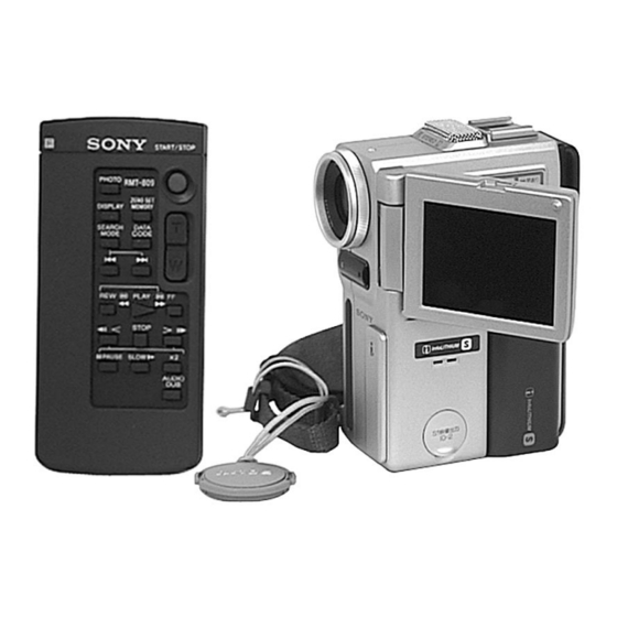
Photo: DCR-PC1E
RMT-809
For MECHANISM ADJUSTMENTS, refer to the "DV MEHCANICAL
ADJUSTMENT MANUAL
supplement: 9-973-815-81) and "DV MECHANICAL ADJUSTMENT
MANUAL
D200 MECHANISM " (original: 9-973-981-11).
SPECIFICATIONS
DIGITAL VIDEO CAMERA RECORDER
RMT-808/809
US Model
Canadian Model
AEP Model
UK Model
Australian Model
Chinese Model
Hong Kong Model
Tourist Model
D MECHANISM " (original: 9-973-815-11,
— Continued on next page —
DCR-PC1
DCR-PC1E
E Model
DCR-PC1/PC1E
Advertisement

Related Manuals for Sony DCR-PC1


Summary of Contents for Sony DCR-PC1
- Page 1 E Model Hong Kong Model Tourist Model Photo: DCR-PC1E D200 MECHANISM RMT-809 DCR-PC1/PC1E DCR-PC1: NTSC model For MECHANISM ADJUSTMENTS, refer to the “DV MEHCANICAL DCR-PC1E: PAL model ADJUSTMENT MANUAL D MECHANISM ” (original: 9-973-815-11, supplement: 9-973-815-81) and “DV MECHANICAL ADJUSTMENT MANUAL D200 MECHANISM ”...
- Page 2 MARK ! ON THE SCHEMATIC DIAGRAMS AND IN THE PARTS CRITIQUES POUR LA SÉCURITÉ DE FONCTIONNEMENT. NE LIST ARE CRITICAL TO SAFE OPERATION. REPLACE THESE REMPLACER CES COMPOSANTS QUE PAR DES PIÈSES SONY COMPONENTS WITH SONY PARTS WHOSE PART NUMBERS DONT LES NUMÉROS SONT DONNÉS DANS CE MANUEL OU APPEAR AS SHOWN IN THIS MANUAL OR IN SUPPLEMENTS DANS LES SUPPÉMENTS PUBLIÉS PAR SONY.
- Page 3 TABLE OF CONTENTS SERVICE NOTE Trouble check ······································································ 1-26 Self-diagnosis function ························································ 1-27 Power Supply During Repairs ············································ 5 Identifying the parts ····························································· 1-28 How to Take a Cassette Out When the Main Power Warning indicators ······························································· 1-30 Cannot Be Turned on ·························································· 5 DISASSEMBLY SELF-DIAGNOSIS FUNCTION 2-1.
- Page 4 • DD-111 (DC/DC Converter) D Page Table ·································································· 5-32 Printed Wiring Board ···································· 4-72 3-3. System Control System Adjustment ······························ 5-34 • DD-111 (DC/DC Converter) Battery End Adjustment (VC-210 board) ······················ 5-34 Schematic Diagram ······································· 4-75 3-4. Servo and RF System Adjustment ································· 5-35 Cap FG Duty Adjustment (MR-40 board) ·····················...
- Page 5 SERVICE NOTE POWER SUPPLY DURING REPAIRS In this unit, about 10 seconds after power is supplied (4.2V) to the battery terminal using the regulated power supply, the power is shut off so that the unit cannot operate. This following two methods are available to prevent this. Take note of which to use during repairs.
- Page 6 SELF-DIAGNOSIS FUNCTION SELF-DIAGNOSIS FUNCTION SELF-DIAGNOSIS DISPLAY When problems occur while the unit is operating, the counter of the When problems occur while the unit is operating, the self-diagnosis function starts working, and displays on the viewfinder or LCD viewfinder shows a 4-digit display consisting of an alphabet and screen what to do.
- Page 7 SELF-DIAGNOSIS CODE TABLE Self-diagnosis Code Block Detailed Symptom/State Correction Function Code Condensation. Remove the cassette, and insert it again after one hour. Video head is dirty. Clean with the optional cleaning cassette. Non-standard battery is used. Use the info LITHIUM battery. LOAD direction.
- Page 8 DCR-PC1/PC1E SECTION 1 This section is extracted from instruction manual GENERAL of DCR-PC1E (3-864-275-51).
- Page 17 1-10...
- Page 18 1-11...
- Page 19 1-12...
- Page 20 1-13...
- Page 21 1-14...
- Page 22 1-15...
- Page 23 1-16...
- Page 24 1-17...
- Page 25 1-18...
- Page 26 1-19...
- Page 27 1-20...
- Page 28 1-21...
- Page 29 1-22...
- Page 30 1-23...
- Page 31 1-24...
- Page 32 1-25...
- Page 33 1-26...
- Page 34 1-27...
- Page 35 1-28...
- Page 36 1-29...
- Page 37 1-30E...
- Page 38 DCR-PC1/PC1E SECTION 2 DISASSEMBLY The following flow chart shows the disassembly procedure. DCR-PC1 2-1. CABINET (L) ASSEMBLY, CABINET (R) ASSEMBLY 1 - @¡ PD-102 board 1 - 6 MD block assembly 2-2. 2-5. 7 , 8 EVF assembly 9 - !£ Microrophone unit 1 - 6 , @™...
- Page 39 2-2. CABINET (L) ASSEMBLY, EVF, MD BLOCK ASSEMBLY !™ Microphone unit !£ Microphone case assembly !¡ Microphone GEL sheet 2 Screw (0-No. +P2 M1.7) !º Microphone retainer plate 9 Pan head small screw 7 Move in the direction of (0-No. special M2 × 4) the arrow a .
- Page 40 2-4. CONTROL SWITCH BLOCK Be sure to disengage the catch. Slant here in the direction of the arrow a and remove it in the direction of the arrow b . 2 Remove an end of the grip belt. Be sure to disengage the catch. !º...
- Page 41 2-5. CABINET (R) ASSEMBLY, PD-102 BOARD Cabinet (R) assembly @£ LCD hinge assembly #• LCD lock pin @™ Two screws #ª LCD lock retainer (M1.7) $º LCD lock #¶ Push the area $¡ Compres- @¢ Remove the shown by the sion coil claw with arrow.
- Page 42 2-6. CD-203 BOARD !º CCD fitting adapter CCD block assembly 4 Two screws 6 CD-203 board 3 Connector (0-No. +P2 B1.7) (CD-203 board CN450) 7 CD frame 2 Peel lens flexible sheet off. 5 Two screws (0-No. +P3 B1.7) VF lens assembly (Refer to sec. 2-7.) 9 Filter block 8 Sealing rubber !¡...
- Page 43 2-8. SERVICE POSITION (Mainly for adjustment) Firstly: Remove the cabinet (R) referring to section 2-1. Then connect the CPC-6 jig, the adjustment remote commander and the AC adapter as shown below. CPC-6 terminal board jig Adjustment remote commander (J-6082-371-A) (RM-95) CPC-6 flexible jig (J-6082-370-A) AC adapter (4.2 Vdc)
- Page 44 2-10.CIRCUIT BOARDS LOCATION VF-125 CD-203 (BACK-LIGHT DRIVE) (CCD IMAGER) PD-102 PR-31 RGB DRIVER, (PANEL REVERSE) TIMING GENERATOR VC-210 CAMERA PROCESS, MECHA SP CONTROL, BLOCKING, CAMERA HI CONTROL, AUDIO PROCESSOR, EVF DRIVER, DC/DC CONVERTER, LINE OUT AMP TB-37 (BATTERY TERMINAL) DD-111 MR-40 (DC/DC CONVERTER) DRUM/CAPSTAN DRIVE,...
- Page 45 2-11.FLEXIBLE BOARDS LOCATION CONTROL SWITCH BLOCK (FK-4780) CONTROL SWITCH BLOCK (ME-4780) FP-586 (From LOADING MOTOR) (From VIDEO HEAD) (From DRUM MOTOR) FP-585 (MODE) (From CAPSTAN MOTOR) 2-8E...
- Page 46 DCR-PC1/PC1E SECTION 3 BLOCK DIAGRAMS 3-1. OVERALL BLOCK DIAGRAM...
- Page 47 CD-203 DD-111 6-2. ELECTRICAL PARTS LIST NOTE: • Due to standardization, replacements in the • RESISTORS When indicating parts by reference number, parts list may be different from the parts All resistors are in ohms. please include the board name. specified in the diagrams or the components METAL: metal-film resistor The components identified by mark ! or...
- Page 48 DD-111 Ref. No. Part No. Description Remarks Ref. No. Part No. Description Remarks C3219 1-164-941-11 CERAMIC CHIP 0.0047uF 10% D3223 8-719-056-61 DIODE MAZS082008SO C3220 1-164-874-11 CERAMIC CHIP 100PF D3224 8-719-056-57 DIODE MAZS091008SO C3221 1-107-682-11 CERAMIC CHIP D3225 8-719-056-57 DIODE MAZS091008SO C3222 1-115-566-11 CERAMIC CHIP 4.7uF...
- Page 49 DD-111 FP-242 FP-584 Ref. No. Part No. Description Remarks Ref. No. Part No. Description Remarks Q3211 8-729-043-94 TRANSISTOR CPH3106-PM-TL R3283 1-218-965-11 RES,CHIP 1/16W Q3212 8-729-043-94 TRANSISTOR CPH3106-PM-TL R3284 1-218-990-11 SHORT Q3213 8-729-044-33 TRANSISTOR CPH6701-TL R3285 1-218-989-11 RES,CHIP 1/16W Q3214 8-729-043-94 TRANSISTOR CPH3106-PM-TL R3286 1-216-864-11 METAL CHIP 1/16W...
- Page 50 < DIODE > C1903 1-117-919-11 TANTAL. CHIP 10uF 6.3V C1904 1-164-943-11 CERAMIC CHIP 0.01uF D2500 8-719-056-23 DIODE MA2S111-(K8).SO D2501 8-719-061-82 DIODE TLSU1002(TPX1,SONY) C1909 1-125-777-11 CERAMIC CHIP 0.1uF D2502 8-719-404-49 DIODE MA111-TX C1910 1-164-943-11 CERAMIC CHIP 0.01uF C1914 1-164-943-11 CERAMIC CHIP 0.01uF...
- Page 51 MR-40 PD-102 Ref. No. Part No. Description Remarks Ref. No. Part No. Description Remarks < COIL > R2517 1-218-989-11 RES,CHIP 1/16W R2530 1-218-971-11 RES,CHIP 1/16W L1803 1-414-771-91 INDUCTOR CHIP 10uH R2531 1-217-671-11 METAL CHIP 1/10W L1804 1-414-771-91 INDUCTOR CHIP 10uH R2532 1-217-671-11 METAL CHIP 1/10W...
- Page 52 PD-102 Ref. No. Part No. Description Remarks Ref. No. Part No. Description Remarks C8009 1-117-919-11 TANTAL. CHIP 10uF 6.3V < TRANSISTOR > C8010 1-125-777-11 CERAMIC CHIP 0.1uF C8011 1-164-943-11 CERAMIC CHIP 0.01uF Q8000 8-729-037-74 TRANSISTOR UN9213J-(K8).SO C8012 1-125-838-91 CERAMIC CHIP 2.2uF 6.3V Q8001...
- Page 53 PD-102 PR-31 TB-37 VC-210 Ref. No. Part No. Description Remarks Ref. No. Part No. Description Remarks R8043 1-218-965-11 RES,CHIP 1/16W C217 1-115-156-11 CERAMIC CHIP R8044 1-218-965-11 RES,CHIP 1/16W C218 1-125-777-11 CERAMIC CHIP 0.1uF R8100 1-218-941-11 RES,CHIP 1/16W C220 1-125-777-11 CERAMIC CHIP 0.1uF R8200 1-218-977-11 RES,CHIP...
- Page 54 VC-210 Ref. No. Part No. Description Remarks Ref. No. Part No. Description Remarks C1423 1-125-839-91 TANTAL. CHIP 47uF 6.3V C2023 1-117-919-11 TANTAL. CHIP 10uF 6.3V C1433 1-164-943-11 CERAMIC CHIP 0.01uF C2028 1-164-943-11 CERAMIC CHIP 0.01uF C1436 1-135-149-21 TANTALUM CHIP 2.2uF C2030 1-109-935-11 TANTAL.
- Page 55 VC-210 Ref. No. Part No. Description Remarks Ref. No. Part No. Description Remarks * C2238 1-125-837-91 CERAMIC CHIP 6.3V CN2904 1-778-595-21 CONNECTOR, BOARD TO BOARD 20P C2400 1-164-937-11 CERAMIC CHIP 0.001uF CN2906 1-785-283-21 PIN, CONNECTOR (PC BOARD) 14P C2402 1-164-850-11 CERAMIC CHIP 10PF 0.5PF CN2908 1-785-282-41 CONNECTOR, BOARD TO BOARD 90P...
- Page 56 VC-210 Ref. No. Part No. Description Remarks Ref. No. Part No. Description Remarks IC2006 8-759-541-70 IC RN5RG28AA-TL Q501 8-729-037-53 TRANSISTOR 2SA1832F-Y/GR(TPL3) IC2200 8-759-398-90 IC S-81236PG-P7-T1 Q502 8-729-037-52 TRANSISTOR 2SC4738F-Y/GR(TPL3) IC2201 8-759-424-79 IC S-8423YFS-T2 Q503 8-729-037-52 TRANSISTOR 2SC4738F-Y/GR(TPL3) IC2203 8-759-536-72 IC TL1596CPWR Q1500 8-729-037-52 TRANSISTOR 2SC4738F-Y/GR(TPL3) IC2204...
- Page 57 VC-210 Ref. No. Part No. Description Remarks Ref. No. Part No. Description Remarks R213 1-218-953-11 RES,CHIP 1/16W R1498 1-218-989-11 RES,CHIP 1/16W R214 1-218-973-11 RES,CHIP 1/16W R1507 1-218-949-11 RES,CHIP 1/16W R217 1-218-945-11 RES,CHIP 1/16W R1508 1-218-959-11 RES,CHIP 3.3K 1/16W R218 1-218-941-11 RES,CHIP 1/16W R1509 1-218-961-11 RES,CHIP...
- Page 58 VC-210 Ref. No. Part No. Description Remarks Ref. No. Part No. Description Remarks R2012 1-218-957-11 RES,CHIP 2.2K 1/16W R2232 1-218-965-11 RES,CHIP 1/16W R2013 1-218-957-11 RES,CHIP 2.2K 1/16W R2233 1-218-958-11 RES,CHIP 2.7K 1/16W R2014 1-218-952-11 RES,CHIP 1/16W R2234 1-218-938-11 RES,CHIP 0.50% 1/16W R2015 1-218-990-11 SHORT R2235...
- Page 59 VC-210 VF-125 Ref. No. Part No. Description Remarks Ref. No. Part No. Description Remarks R2297 1-218-953-11 RES,CHIP 1/16W R3416 1-218-969-11 RES,CHIP 1/16W R2298 1-218-953-11 RES,CHIP 1/16W R3417 1-208-943-11 RES,CHIP 220K 0.50% 1/16W R2299 1-218-953-11 RES,CHIP 1/16W R3418 1-218-978-11 RES,CHIP 120K 0.50% 1/16W R2300 1-218-953-11 RES,CHIP...
- Page 60 VF-125 Ref. No. Part No. Description Remarks Ref. No. Part No. Description Remarks < TRANSISTOR > ACCESSORIES ************ Q5500 8-729-037-52 TRANSISTOR 2SC4738F-Y/GR(TPL3) Q5501 8-729-037-52 TRANSISTOR 2SC4738F-Y/GR(TPL3) 1-475-141-21 COMMANDER, REMOTE (RMT-808) Q5502 8-729-037-52 TRANSISTOR 2SC4738F-Y/GR(TPL3) (PC1/PC1E:EXCEPT AEP,UK) Q5503 8-729-037-52 TRANSISTOR 2SC4738F-Y/GR(TPL3) 1-475-141-31 COMMANDER, REMOTE (RMT-809) Q5504 8-729-037-52 TRANSISTOR 2SC4738F-Y/GR(TPL3)
- Page 61 〈PARTS REFERENCE SHEET〉 You can find the parts position of location of mount locations applying to MR-40 board of a set. MR-40 SIDE A DCR-PC1/PC1E IC2500 I C 1 6 0 0 CN2501 M R - 4 0 S I D E B D C R - P C 1 / P C 1 E 〈PARTS REFERENCE SHEET〉...
- Page 62 〈 〉 OPTICAL AXIS FRAME Take a copy of CAMERA COLOR REPRODUCTION FRAME and Parts referencesheets with a clear sheet for use. — 216 —...
- Page 63 〈 〉 FOR CAMERA COLOR REPRODUCTION ADJUSTMENT For NTSC model DCR-PC1 Take a copy of CAMERA COLOR REPRODUCTION FRAME and Parts referencesheets with a clear sheet for use. For PAL model DCR-PC1E — 217 —...
- Page 64 DCR-PC1/PC1E Sony Corporation 98G1649-1 Printed in Japan ©1998.7 Personal A&V Products Company 9-974-094-11 Published by Quality Engineering Dept. — 218 — (Osaki East)