Table of Contents
Advertisement
Quick Links
TH450A-CRB
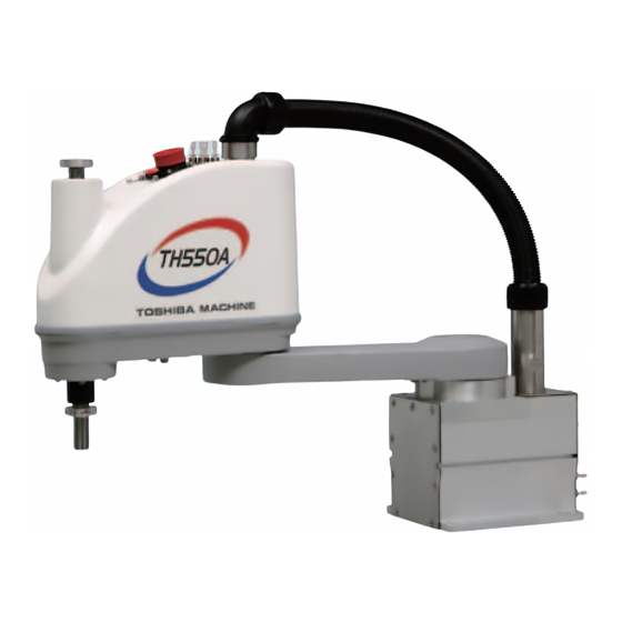
TH550A-CRB
THP550-CRB/TS3000
INSTRUCTION MANUAL
INDUSTRIAL ROBOT SPECIFICATIONS
Make sure that this instruction manual is delivered to the final
user of Toshiba Machine's industrial robot.
Before operating the industrial robot, read through and
completely understand this manual.
After reading through this manual, keep it nearby for future
reference.
CLEAN TYPE
Notice
May 2010
TOSHIBA MACHINE CO., LTD.
NUMAZU, JAPAN
STE 80872-0
Advertisement
Table of Contents

Related Manuals for Toshiba TH450A-CRB


Summary of Contents for Toshiba TH450A-CRB
- Page 1 INDUSTRIAL ROBOT SPECIFICATIONS Notice Make sure that this instruction manual is delivered to the final user of Toshiba Machine’s industrial robot. Before operating the industrial robot, read through and completely understand this manual. After reading through this manual, keep it nearby for future reference.
- Page 2 CLEAN TYPE SPECIFICATIONS MANUAL Copyright 2010 by Toshiba Machine Co., Ltd. All rights reserved. No part of this document may be reproduced in any form without obtaining prior written permission from Toshiba Machine Co., Ltd. The information contained in this manual is subject to change without prior notice to effect improvements.
- Page 3 CLEAN TYPE SPECIFICATIONS MANUAL Preface This manual describes the specifications of the TH–A and THP series clean type industrial robots. This manual is essential to keep the robot performance for a long time, to prevent failures and to assure safety. Be sure to look through this manual and set up a maintenance program before actually starting the robot.
- Page 4 CLEAN TYPE SPECIFICATIONS MANUAL [Explanation of symbols] Symbol Meaning of symbol This means that the action is prohibited (must not be done). Details of the actions actually prohibited are indicated with pictures or words in or near the symbol. This means that the action is mandatory (must be done). Details of the actions that must be done are indicated with pictures or words in or near the symbol.
- Page 5 Disassembly prohibited • Always use the Toshiba Machine's designated spare parts when replacing the parts. • Maintenance and inspection should be performed regularly. Otherwise, the system may malfunction or accidents will be Mandatory caused.
- Page 6 CLEAN TYPE SPECIFICATIONS MANUAL This manual is comprised of the following six (6) sections: Section 1 Specifications This section describes the basic specifications and names of respective parts of the clean type industrial robot. Section 2 Transportation This section describes how to remove the clean type robot from its box and how to transport it to the installation site.
-
Page 7: Table Of Contents
CLEAN TYPE SPECIFICATIONS MANUAL Table of Contents Page Specifications ......................8 Name of Each Part ..................8 Outer Dimensions ....................9 Specifications Table..................15 Transportation ......................19 Unpacking and Transport ................19 Mass and Outer Dimensions .................19 Cautions on Transporting the Robot ..............21 Installation ......................23 Installation Environment ................23 Air Suction Volume ..................24 Coordinate System ..................25 Installing the Robot ..................27... -
Page 8: Specifications
CLEAN TYPE SPECIFICATIONS MANUAL Specifications Name of Each Part The names of respective parts of the clean type robot are shown in Fig. 1.1 below. Axis 2 (rotation) Wiring panel Bellows (upper) Cover Axis 1 (rotation) Arm 2 Bellows (lower) Arm 1 Ball screw spline (tool shaft) -
Page 9: Outer Dimensions
Fig. 1.2 to Fig. 1.4 show the outer dimensions of the robot and Fig. 1.5 to Fig. 1.7 show the operating range of the robot. Space required for cable connection Fig. 1.2 Outer dimensions of the robot (TH450A-CRB) STE 80872-0 – 9 –... - Page 10 CLEAN TYPE SPECIFICATIONS MANUAL Space required for cable connection Fig. 1.3 Outer dimensions of the robot (TH550A-CRB) STE 80872-0 – 10 –...
- Page 11 CLEAN TYPE SPECIFICATIONS MANUAL Stroke 150 mm (upper limit) Stroke 300 mm (upper limit) Space required for cable connection Fig. 1.4 Outer dimensions of the robot (THP550-CRB) STE 80872-0 – 11 –...
- Page 12 CLEAN TYPE SPECIFICATIONS MANUAL Fig. 1.5 Operating range of the robot (TH450A-CRB) STE 80872-0 – 12 –...
- Page 13 CLEAN TYPE SPECIFICATIONS MANUAL Fig. 1.6 Operating range of the robot (TH550A-CRB) STE 80872-0 – 13 –...
- Page 14 CLEAN TYPE SPECIFICATIONS MANUAL Fig. 1.7 Operating range of the robot (THP550-CRB) STE 80872-0 – 14 –...
-
Page 15: Specifications Table
CLEAN TYPE SPECIFICATIONS MANUAL Specifications Table [TH450A-CRB/TH550A-CRB] Item Specifications Structure Horizontal multi-joint type SCARA robot Model TH450A–CRB TH550A–CRB Applicable controller TS3000 (*1) Mass of robot body 28 kg 29 kg No. of controlled axes Four (4) Arm length 450 mm (200 + 250) - Page 16 CLEAN TYPE SPECIFICATIONS MANUAL Item Specifications Ten (10) or less dust particles of 0.1 μm or Cleanness level (*5) over in diameter, which exist in 1 cft (28,317 ) of a sample area. Equivalent to clean class 3 defined by ISO Air suction volume 60 normal liters/min The structure of the robot controller is not of a clean type.
- Page 17 CLEAN TYPE SPECIFICATIONS MANUAL [THP550-CRB] Item Specifications Structure Horizontal multi-joint type SCARA robot Model THP550–CRB Applicable controller TS3000 (*1) Mass of robot body 27 kg No. of controlled axes Arm length 550 mm (300 + 250) Axis 1 1000 (W) Axis 2 400 (W) Motor capacity...
- Page 18 CLEAN TYPE SPECIFICATIONS MANUAL The structure of the robot controller is not of a clean type. When the mass of load exceeds 1 kg, or when the gravity center position of load is away from the axis 4 center position, both the speed and acceleration should be reduced, using the PAYLOAD command.
-
Page 19: Transportation
The mass and outer dimensions of the robot at the time of transport are shown in Figs. 2.1 to 2.3. Mass of main robot = 28 kg Clamp Fig. 2.1 Outer dimensions at transport (TH450A-CRB) STE 80872-0 – 19 –... - Page 20 CLEAN TYPE SPECIFICATIONS MANUAL Mass of main robot = 29 kg Clamp Fig. 2.2 Outer dimensions at transport (TH550A-CRB) Mass of main robot = 27 kg Clamp Fig. 2.3 Outer dimensions at transport (THP550-CRB) STE 80872-0 – 20 –...
-
Page 21: Cautions On Transporting The Robot
CLEAN TYPE SPECIFICATIONS MANUAL Cautions on Transporting the Robot The clean type robot equals the standard robot added with two (2) bellows. The precautions to be taken at transport are stated below. The precautions other than the below are the same as in the standard robot. For details, see the TH450A/TH550A/TS3000 Installation and Transportation Manual or the THP550/TS3000 Installation and Transportation Manual provided separately. - Page 22 CLEAN TYPE SPECIFICATIONS MANUAL After the installation, remove the clamp and eyebolt used for transport. CAUTION • When lifting up the robot by workers, hold the shaded locations by hands, as shown in Fig. 2.4. If the ball screw spline shaft is held by hands, an unusually large force is exerted, resulting in a malfunction.
-
Page 23: Installation
CLEAN TYPE SPECIFICATIONS MANUAL Installation Installation Environment Table 3.1 shows the environmental conditions for the location in which the robot and controller are to be installed. Table 3.1 Environmental conditions for robot and controller Item Specifications Temperature In operation 0 to 40°C In storage –10 to 50°C Humidity... -
Page 24: Air Suction Volume
CLEAN TYPE SPECIFICATIONS MANUAL Air Suction Volume It is possible to maintain the equivalent to clean class 3 defined by ISO by sucking a specified volume of air from the quick-operated joint for air suction attached to the base cover (i.e., connector unit of the base). The air suction unit and suction air tube (8mm-dia.) should be provided by the customer. -
Page 25: Coordinate System
Figs. 3.1 to 3.2 show the base coordinate system (XB, YB, ZB) and origin of each axis joint angle. (–) (–) (–) Origin of base coordinate system (Z-axis standard stroke) (–) Fig. 3.1 Base coordinate system and joint angle origin (TH450A-CRB/TH550A-CRB) STE 80872-0 – 25 –... - Page 26 CLEAN TYPE SPECIFICATIONS MANUAL (–) (–) (–) Origin of base coordinate system Z stroke 150 mm (Z-axis standard stroke) (upper limit) Axis 3 Z stroke 350 mm (upper limit) (–) Origin of base coordinate system (Z-axis long stroke) Fig. 3.2 Base coordinate system and joint angle origin (THP550-CRB) STE 80872-0 –...
-
Page 27: Installing The Robot
CLEAN TYPE SPECIFICATIONS MANUAL Installing the Robot The robot is secured, using the set holes on the base (four (4) places). Use M12 hexagon socket head cap screws (made of stainless steel). The robot installation method is shown in Fig. 3.3. The reference surfaces are provided on the base. -
Page 28: Tool Interface
CLEAN TYPE SPECIFICATIONS MANUAL Tool Interface Mounting of a tool and tool signals are the same as in the standard robot. For details, see the TH450A/TH550A/TS3000 Installation and Transportation Manual or the THP550/TS3000 Installation and Transportation Manual provided separately. Tool Air Piping The robot is provided with four (4) air lines for the tool. - Page 29 CLEAN TYPE SPECIFICATIONS MANUAL Air joint pitches of the panel Fig. 4.1 Tool air piping STE 80872-0 – 29 –...
-
Page 30: Maintenance
CLEAN TYPE SPECIFICATIONS MANUAL Maintenance Items for Maintenance and Inspection The maintenance schedule and maintenance procedures for the clean type robot are shown in Table 5.1 below. The basic structure of the clean type robot is the same as that of the standard robot. For the maintenance schedule, maintenance procedures, contents of inspection, etc., see the THP550/TH450A/TH550A Maintenance of Instruction Manual provided separately. -
Page 31: Check For Bellows
CLEAN TYPE SPECIFICATIONS MANUAL 5.1.1 Check for Bellows Visually make sure that each bellows is not found broken, worn out, twisted or folded during robot operation or stop. If it is found broken or worn out, the cleanness level will drop. Replace it with a new one immediately. -
Page 32: Layout Of Robot Components
Ball screw spline shaft Bellows (lower) Battery box Axis 1 motor Fig. 5.1 Layout of robot mechanical components (TH450A-CRB/TH550A-CRB) CAUTION • When replacing the bellows with a new one or when mounting and dismounting the cover, dust will generate. Before starting the work, therefore, move the robot to a place where dust generation poses no problem at all. - Page 33 CLEAN TYPE SPECIFICATIONS MANUAL Shaft for bellows Bellows (upper) Axis 3 motor Axis 4 motor * Placed in parallel. Axis 2 motor Axis 2 reduction gear Axis 1 reduction gear Axis 3 timing belt Axis 4 timing belt Axis 4 reduction gear Ball screw spline shaft Battery box Bellows (lower)
-
Page 34: Mounting And Dismounting Covers
CLEAN TYPE SPECIFICATIONS MANUAL Mounting and Dismounting Covers Packing is attached to each cover set surface of the clean type robot. Strictly observe the following procedures to mount and dismount each cover. DANGER • Before mounting and dismounting each cover, be sure to turn off the main power (“POWER”) switch. -
Page 35: Arm 1 Covers
The arm 1 covers are provided above the axis 1 (arm cover 1). Each cover is secured to the arm 1 with eight (8) cross-recessed truss head screws (M4 × 6) by inserting the packing. Arm cover Packing Fig. 5.4 Arm 1 cover TH450A-CRB/TH550A-CRB STE 80872-0 – 35 –... - Page 36 CLEAN TYPE SPECIFICATIONS MANUAL Arm cover Packing Fig. 5.5 Arm 1 cover THP550-CRB CAUTION • Be sure to attach the packing when mounting the cover. Otherwise, the cleanness level will deteriorate. STE 80872-0 – 36 –...
-
Page 37: Arm 2 Cover
CLEAN TYPE SPECIFICATIONS MANUAL 5.3.3 Arm 2 Cover The arm 2 cover is secured to the cover securing bracket with twelve (12) hexagon socket head bolts (M4 × 8). Due to the clean type robot, the bellows (upper) is attached to the cover. To dismount the arm 2 cover, the bellows should be disconnected first. -
Page 38: Replacing Bellows
CLEAN TYPE SPECIFICATIONS MANUAL Replacing Bellows DANGER • Before replacing the bellows with a new one, be sure to turn off the controller power and remove the power plug. 5.4.1 Replacement Procedures for Bellows (Lower) Remove the tool flange, followed by the keep plate under the bellows. Remove the keep plate above the bellows, then pull the bellows downward. -
Page 39: Replacement Procedures For Bellows (Upper)
CLEAN TYPE SPECIFICATIONS MANUAL CAUTION • When dismantling the bellows, DO NOT pull it out by force. Otherwise, the bellows may rupture. • Be sure to attach the packing. Otherwise, the cleanness level will deteriorate. 5.4.2 Replacement Procedures for Bellows (Upper) Remove the three (3) set screws (3 ×... - Page 40 CLEAN TYPE SPECIFICATIONS MANUAL Wiring guide Bellows Set screw Upper keep plate Lower keep plate Packing adhered to the bearing case Bearing case Packing Bellows set ring No need to be removed Arm 2 cover Fig. 5.7 Bellows (upper) To mount the bellows, observe the above steps in the reversed order. Be sure to attach the packing.
-
Page 41: Replacement Parts For Maintenance
CLEAN TYPE SPECIFICATIONS MANUAL Replacement Parts for Maintenance Replacement Parts List for Maintenance Our dwg. Part name Unit code Stroke Q’ty Remarks Bellows S854575 Y610A3GH0 Z150 TH450A-CRB/TH550A-CRB Bellows S849728 Y610A3F90 Z150 THP550-CRB Bellows S854887 Y610A3FT0 Z300 THP550-Z-CRB Ball-screw H846618 Y610A3GF0... - Page 42 CLEAN TYPE SPECIFICATIONS MANUAL APPROVED BY: CHECKED BY: PREPARED BY: STE 80872-0 – 42 –...