Table of Contents
Advertisement
Quick Links
Advertisement
Table of Contents

Related Manuals for Motorola STARLINE SLE Series


Summary of Contents for Motorola STARLINE SLE Series
- Page 1 Installation and Operation Manual SLE*-* STARLINE Line Extender...
- Page 2 Operation of this equipment in a residential area is likely to cause harmful interference in which case the user will be required to correct the interference at his/her own expense. Any changes or modifications not expressly approved by Motorola could void the user’s authority to operate this equipment under the rules and regulations of the FCC.
- Page 3 Motorola, Inc. Motorola reserves the right to revise this publication and to make changes in content from time to time without obligation on the part of Motorola to provide notification of such revision or change. Motorola provides this guide without warranty of any kind, either implied or expressed, including, but not limited to, the implied warranties of merchantability and fitness for a particular purpose.
-
Page 4: Table Of Contents
Flatness Control..................................3-6 Directional Coupler Test Points............................. 3-8 SLE-Bode Equalization................................3-8 Amplifier Level Control................................3-9 Manual Gain Control ..............................3-9 SLE-TDU..................................3-10 SLE-ADU..................................3-11 SLE-ADU Pads and Levels ............................3-12 PRELIMINARY - Motorola Internal Use Only SLE*-* Installation and Operation Manual... - Page 5 Return Path ...................................... A-2 SLE-ADU......................................A-2 Appendix B Torque Specifications Figures Figure 1-1 SLE*-* closed................................1-1 Figure 1-2 SLE*-* open..................................1-2 Figure 2-1 SLE*-* base ..................................2-1 Figure 2-2 SLE*-* configurator ...............................2-2 SLE*-* Installation and Operation Manual PRELIMINARY - Motorola Internal Use Only...
- Page 6 Table 3-1 STARLINE Forward Equalizers – SFE*-* ........................3-3 Table 3-2 STARLINE cable simulators............................3-5 Table 3-3 Gain reserve versus ambient temperature ........................3-9 Table 3-4 SLE-ADU pad levels ..............................3-12 PRELIMINARY - Motorola Internal Use Only SLE*-* Installation and Operation Manual...
-
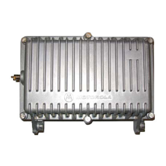
Page 7: Figure 1-1 Sle*-* Closed
−20 dB directional coupler test points ® Optional return path ingress control and LIFELINE status monitor Two-way operation capability 10-amp power passing Figure 1-1 illustrates a closed SLE*-* line extender: Figure 1-1 SLE*-* closed PRELIMINARY - Motorola Internal Use Only SLE*-* Installation and Operation Manual... -
Page 8: Figure 1-2 Sle*-* Open
CURRENT: 1.5 AMPS DC CAUTION VOLTAGES IN EXCESS OF 300 VOLTS ARE PRESENT UNDER COVER AND MAY BE PRESENT AFTER POWER IS REMOVED CONSULT INSTALLATION MANUAL PRIOR TO REMOVING PROTECTIVE COVER. SLE*-* Installation and Operation Manual PRELIMINARY - Motorola Internal Use Only... -
Page 9: Introduction
When the information applies to a specific model, the complete model number is given. Italic type Denotes a displayed variable, a variable that you must type, or is used for emphasis. PRELIMINARY - Motorola Internal Use Only SLE*-* Installation and Operation Manual... -
Page 10: If You Need Help
Introduction If You Need Help If you need assistance while working with the SLE*-*, contact the Motorola Technical Response Center (TRC): ! Inside the U.S.: 1-888-944-HELP (1-888-944-4357) ! Outside the U.S.: 215-323-0044 ! Motorola Online: http://businessonline.motorola.com The TRC is open from 8:00 AM to 7:00 PM Eastern Time, Monday through Friday and 10:00 AM to 5:00 PM Eastern Time, Saturday. -
Page 11: Calling For Repairs
Introduction Calling for Repairs If repair is necessary, call the Motorola Repair Facility at 1-800-642-0442 or e-mail nogrepaircenter@motorola.com for a Return for Service Authorization (RSA) number before sending the unit. The RSA number must be prominently displayed on all equipment cartons. -
Page 12: Overview
D A M AG E B Y E LE C TR O STATIC SE LECTOR -16 dB REFER TO D IS C HA R GE ( ESD ) REFER TO MANUAL MANUAL FOR FUSE VA LUES PRELIMINARY - Motorola Internal Use Only SLE*-* Installation and Operation Manual... -
Page 13: Configuration
Overview Configuration The SLE*-* is fully configured by Motorola per customer request. It is recommended that you verify the configuration listed on the outside of the shipping carton with the configuration you ordered. The shipped configuration is also noted on labels located on the side of the housing. -
Page 14: Housing
For strand mounting, use the two messenger clamps located on the side of the housing (Figure 2-5) that are secured with 5/16 inch × 24 threads-per-inch stainless steel bolts. Use the “L” bracket feature for pedestal and surface mounting installations. PRELIMINARY - Motorola Internal Use Only SLE*-* Installation and Operation Manual... -
Page 15: Gaskets
VOLTAGES IN EXCESS OF 300 VOLTS ARE PRESENT UNDER COVER AND MAY BE PRESENT AFTER POWER IS REMOVED CONSULT INSTALLATION MANUAL PRIOR TO REMOVING PROTECTIVE COVER. RF gasket (woven wire) SLE*-* Installation and Operation Manual PRELIMINARY - Motorola Internal Use Only... -
Page 16: Port Locations
Figure 2-5 illustrates the housing port locations: Figure 2-5 Housing ports Messenger clamp bolts Output Input port 1 port AC test point Return Output test port 2 point PRELIMINARY - Motorola Internal Use Only SLE*-* Installation and Operation Manual... -
Page 17: Power Supply
Because these losses are located interstage, the noise figure is only significantly impacted by the insertion loss of the forward cable equalizer or broadband cable simulator, and the input pad if its value is increased from zero. SLE*-* Installation and Operation Manual PRELIMINARY - Motorola Internal Use Only... -
Page 18: Return Path
The return-input test point and the return-output test point are −20 dB directional couplers. Both test points present 75-ohm source impedance and do not require special test probes. PRELIMINARY - Motorola Internal Use Only SLE*-* Installation and Operation Manual... -
Page 19: Ingress Control Switch
LL-SLE-HMS-*/*. (Figure 2-8 illustrates the location of the optional ICS). Please consult your Motorola sales representative for the availability of LL-SLE-HMS-*/*. To properly install the LL-SLE-HMS-*/*, the deeper housing cover (SLE-LID/SM is required. The ICS provides a means of isolating sources of ingress from a centralized location. Using a downstream command through the LIFELINE status-monitoring system, you can attenuate the return path through the line extender by 6 dB or by 38 dB. - Page 20 6 dB or cutoff of 38 dB typical. The unit is shipped with a jumper in this location. PRELIMINARY - Motorola Internal Use Only SLE*-* Installation and Operation Manual...
- Page 21 In the event of SLE-ADU or SLE-TDU failure, you can select manual control of the Bode board. Figure 2-8 illustrates the location of the jumper on the main circuit board. AUTO SLE*-* Installation and Operation Manual PRELIMINARY - Motorola Internal Use Only...
-
Page 22: Amplifier Setup
This is caused by factors such as walkout errors, worst-case data utilization during design, and temperature variation from 70°F. Perform a bench alignment. Pre-aligning the SLE*-* response on the bench (Section 4, “Bench Testing”) for a system signature simplifies field alignment. PRELIMINARY - Motorola Internal Use Only SLE*-* Installation and Operation Manual... -
Page 23: Cable Equalizer
2 signal input level to the line extender is 12 dB greater (16 – 4 = 12) at channel 2 than it is at 870 MHz. Our example assumes that the high-end frequency level into the amplifier is +15 dBmV. SLE*-* Installation and Operation Manual PRELIMINARY - Motorola Internal Use Only... - Page 24 STARLINE Forward Equalizers – SFE*-* Frequency (MHz) versus Insertion Loss (dB) Equalizer Equalizer Value Slope SFE-87- 16.7 17.7 12.4 10.0 15.2 16.2 11.4 13.7 14.7 10.3 12.1 13.1 10.6 11.6 10.1 PRELIMINARY - Motorola Internal Use Only SLE*-* Installation and Operation Manual...
- Page 25 Because of errors in cable attenuation, slope in passive devices, and other independent variables, you may need to change the final value of the equalizer before you install the SLE*-*. SLE*-* Installation and Operation Manual PRELIMINARY - Motorola Internal Use Only...
-
Page 26: Starline Cable Simulators
-8.0 -9.0 -10.0 870 MHz -1.1 -2.2 -3.3 -4.4 -5.5 -6.7 -7.8 -8.9 -10.0 -11.1 50 MHz loss (typical) -1.0 -1.0 -1.0 -1.0 -1.0 -1.0 -1.0 -1.0 -1.0 -1.0 PRELIMINARY - Motorola Internal Use Only SLE*-* Installation and Operation Manual... -
Page 27: Input And Midstage Pads
C1 produces a peak that is centered just below the lowest forward frequency and varied in amplitude by R1. C2 produces a peak that is centered approximately 50 MHz above the lowest forward frequency and varied in amplitude by R2. SLE*-* Installation and Operation Manual PRELIMINARY - Motorola Internal Use Only... - Page 28 L4, on the bottom of the LDR board, may slightly tune the upper portion of the response. Excessive spreading of L4 will increase insertion loss. Figure 3-3 illustrates the LDR/*/III: Figure 3-3 8LDR/*/III component layout (top-left, bottom-right) PRELIMINARY - Motorola Internal Use Only SLE*-* Installation and Operation Manual...
-
Page 29: Directional Coupler Test Points
) in Figure 2-8. To install the SLE-Bode board, remove the chassis cover and remove the jumper at the (jumper or optional SLE-Bode) location (Fig. 2-8). Replace with the SLE-Bode. SLE*-* Installation and Operation Manual PRELIMINARY - Motorola Internal Use Only... -
Page 30: Amplifier Level Control
32° ° ° ° F (0° ° ° ° C) to 110° ° ° ° F (43° ° ° ° C) 4 dB Below 32° ° ° ° F (0° ° ° ° C) 5 dB PRELIMINARY - Motorola Internal Use Only SLE*-* Installation and Operation Manual... -
Page 31: Sle-Tdu
= 30 dB or more of cable. Figure 3-5 illustrates the jumper and thermal level control on the SLE-TDU: Figure 3-5 SLE-TDU cable selector Thermal Medium level High SLE*-* Installation and Operation Manual PRELIMINARY - Motorola Internal Use Only... -
Page 32: Sle-Adu
FWD OUT edge carrier. Turn the auto level control potentiometer on the SLE-ADU fully clockwise and then reduce to obtain the level obtained in Step 8 under Manual Gain Control. PRELIMINARY - Motorola Internal Use Only SLE*-* Installation and Operation Manual... -
Page 33: Sle-Adu Pads And Levels
Full complement of JXP-*B pads and STARLINE Return Equalizers (SRE-*-*) Reverse signal generator — must produce at least one signal within the return bandpass and have variable output Return sweep or alignment equipment SLE*-* Installation and Operation Manual PRELIMINARY - Motorola Internal Use Only... -
Page 34: Alignment Procedure
Return levels used for alignment are not necessarily operational system levels. These levels vary from system to system due to differences in equipment, architectures, and design philosophies. For an in-depth analysis and discussion of the return path, refer to Motorola reference guide Return Path Level Selection, Setup, and Alignment Procedure. -
Page 35: Powering And Surge Protection
To avoid possible injury to personnel or damage to the equipment, remove 60/90 volt AC power from the system before you remove any components from the housing. The SLE*-* is shipped from the factory configured for 38 through 90 VAC powering as described in Section 2, “Overview.” SLE*-* Installation and Operation Manual PRELIMINARY - Motorola Internal Use Only... -
Page 36: Bench Testing
Section 4 Bench Testing Motorola’s recommended procedure for placing a new SLE*-* into service is to fully test it on the bench before it is field installed. There are specific alignment procedures that ensure proper functioning of all components and simplify final installation. If the SLE*-* is properly aligned on the bench only minor adjustments may be required in the field. -
Page 37: Test Equipment And Connections
The equipment typically used for testing the SLE*-* consists of a network analyzer such as the HP 8712 or 8713 series, a 60/90 VAC bench power supply, a cable simulator, a Motorola model SSP-PIN power combiner, and a variety of jumper cables, adapters, and fittings. - Page 38 The result is the peak-to-valley (P-V) flatness. Some improvement is possible by adjusting the flatness controls on the LDR/*/III board as described in Section 3, “Amplifier Setup,” Flatness Control. Figure 3-3 illustrates the location of these controls on the LDR/*/III board. PRELIMINARY - Motorola Internal Use Only SLE*-* Installation and Operation Manual...
-
Page 39: Testing Return Gain And Response
Re-install the fuse or power-block removed during testing. Complete station records by recording pertinent information. Remove test-equipment connections and close the housing following instructions provided in Section 5, “Installation,” Closing the Housing. SLE*-* Installation and Operation Manual PRELIMINARY - Motorola Internal Use Only... -
Page 40: Installation
Apply power to the unit and allocate a few minutes for warm-up. Check the DC voltage. Verify that it is between 23.6 V and 24.4 V and re-install the input pad. PRELIMINARY - Motorola Internal Use Only SLE*-* Installation and Operation Manual... - Page 41 Close the housing and use a torque wrench to sequentially and progressively tighten the housing bolts to a final torque of 6 ft-lb in the sequence specified on the housing cover and illustrated in Figure 5-2. Figure 5-2 Torque sequence SLE*-* Installation and Operation Manual PRELIMINARY - Motorola Internal Use Only...
-
Page 42: Pedestal Installation
To surface mount the SLE*-*, insert 5/16-inch bolts through the pre-drilled holes on the “L” bracket portion of the messenger clamp and into the anchoring surface. All other instructions for surface mounting are similar to the pedestal installation. PRELIMINARY - Motorola Internal Use Only SLE*-* Installation and Operation Manual... -
Page 43: Operating Tips
E-GaAs SLE*-*s, this should not be a major concern assuming the pad value is reasonable. It is recommended that you contact Motorola’s TRC or your account representative for specific information regarding use of the midstage pads. -
Page 44: Specifications
Specifications are valid over the given bandpass and operating temperature range of −40°F to +140°F (−40°C to +60°C). Specifications stated are typical unless otherwise noted, and are subject to change. Refer to the Motorola BCS Web site or contact your account representative for the latest specifications. -
Page 45: Ac Current
±6 MHz Adjacent channel frequency Minimum BLE*/* output at pilot frequency +36 dBmV ±0.3 output change for ±3.0 dB input change ALC stiffness Power requirement 24 VDC, 75 mA SLE*-* Installation and Operation Manual PRELIMINARY - Motorola Internal Use Only... -
Page 46: Torque Specifications
3/16 inch or Phillips Hybrid #6-32 Phillips 10-12 0.8-1.0 1.1-1.4 Chassis cover #6-32 1/4 inch or 10-12 0.8-1.0 1.1-1-4 Phillips Status monitor #10-32 5/16 inch 24-30 2.0-2.5 2.7-3.4 triple lead PRELIMINARY - Motorola Internal Use Only SLE*-* Installation and Operation Manual... - Page 47 NTSC National Television Standards Committee root-mean-square Return for Service Authorization Surface Acoustic Wave SCS-* Starline Cable Simulator SFE-*-* Starline Forward Equalizer SRE-*-* Starline Return Equalizer SLE-TDU SLE-Thermal Drive Unit PRELIMINARY - Motorola Internal Use Only SLE*-* Installation and Operation Manual...
- Page 48 Visit our website at: www.motorola.com 509836-001 11/04 MGBI...