Table of Contents
Advertisement
Advertisement
Table of Contents

Related Manuals for Bosch Compress 7400i AW


Summary of Contents for Bosch Compress 7400i AW
- Page 1 Installer Guide Air to water heat pump Compress 7400i AW 5 OR | 7 OR...
-
Page 2: Table Of Contents
Any damage that is caused by Information on refrigerant ..... . . 24 such usage is excluded from liability. Compress 7400i AW – 6721833372 (2021/09) -
Page 3: Regulations
• EN 1717 (Protection against pollution of potable water installations www.sentinelprotects.com/uk and general requirements of devices to prevent pollution by backflow) Table 3 • EN 378 (Refrigerating systems and heat pumps - Safety and environmental requirements) 1) Only applicable in the United Kindgom. Compress 7400i AW – 6721833372 (2021/09) - Page 4 / cm. To prevent oxygen from entering the heating water, the expansion vessel must be adequately dimensioned. When installing diffusion open pipes, a system separation with the help of a heat exchanger is required. Compress 7400i AW – 6721833372 (2021/09)
-
Page 5: Product Description
AWE is equipped with an integrated electric booster heater. is intended for an auxiliary heater (electric, oil and gas heating) with mixer. 1) Not available in United Kingdom. 2) Not available in United Kingdom and Ireland. Compress 7400i AW – 6721833372 (2021/09) -
Page 6: Product Overview
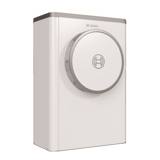
Dimensions and connections of heat pump models 5 OR-7 OR, Pressure switch/pressure sensor rear compressor Inverter Description applies for all sizes. ø10,5 0010031841-002 Fig. 5 Dimensions of heat pump models 5 OR-7 OR, view from top Compress 7400i AW – 6721833372 (2021/09) -
Page 7: Clearances During Setup
The drain must slope sufficiently to prevent water from accumulating in the pipe. The condensate can be routed to either a gravel bed, a stone box or into a rainwater gully. Compress 7400i AW – 6721833372 (2021/09) -
Page 8: Minimum Volume And Execution Of The Heating System
Instead, the system volume is considered to be sufficient if certain conditions are met. Underfloor heating system without buffer cylinder A room temperature-dependent control unit should be installed in the largest room (reference room) instead of room thermostats. Small floor Compress 7400i AW – 6721833372 (2021/09) -
Page 9: Transport Fitting
▶ Before connecting the heat pump and indoor unit, rinse the pipe 4. Connect CAN-BUS cable to heat pump and indoor unit. system to remove any foreign bodies. 5. Connect power supply of the heat pump. 6. Mount side panels and cover of heat pump. Compress 7400i AW – 6721833372 (2021/09) - Page 10 ▶ Establish the connection to the heat pump using a vibration-damping hose which is suitable for use outdoors and also insulate it. 0010036852-001 Fig. 13 Pipe length A Indoor unit wall mounted Heat pump Compress 7400i AW – 6721833372 (2021/09)
-
Page 11: Water Connecting Pipe
The condensate can be routed to either a gravel bed, a stone box or into a rainwater gully. ▶ Route 32 mm plastic pipe from the condensate connection to a drain. ▶ Connection of pipe trace heating Chapter 7.1. Compress 7400i AW – 6721833372 (2021/09) -
Page 12: Connection Of Heat Pump To The Indoor Unit
The communication circuits are not designed for 12 V constant voltage. ▶ Check to ensure that the cables are connected to the contacts with the corresponding markings on the modules. The heat pump and indoor unit are connected by a communication line, CAN-BUS. Compress 7400i AW – 6721833372 (2021/09) - Page 13 ▶ Tighten all cable fixings if required. ▶ Reattach the cover of the control device. ▶ Reattach the belt. Fig. 16 Termination CAN-BUS Fig. 17 Cable conduits and control device Cable conduit, power supply Cable conduit CAN-BUS Connection CAN-BUS Compress 7400i AW – 6721833372 (2021/09)
-
Page 14: Installing Side Panels And Cover
Risk of injury! There is a risk of hand injury if the fan is uncovered. ▶ The unit may not be commissioned without the front plate. 0010029644-001 Fig. 18 Installing side panels and cover Compress 7400i AW – 6721833372 (2021/09) - Page 15 Installation 0010029645-001 Fig. 19 Installing side panels and cover Compress 7400i AW – 6721833372 (2021/09)
-
Page 16: Maintenance
The electronic expansion valves are highly sensitive to impacts. Install power cable ▶ Always protect the expansion valve from impacts and shock. ▶ Check the power cable for mechanical damage. ▶ Replace damaged cables. Installation of accessories Heating cable Compress 7400i AW – 6721833372 (2021/09) - Page 17 Installation of accessories Compress 7400i AW – 6721833372 (2021/09)
-
Page 18: Environmental Protection And Disposal
For additional information on the environmentally compatible disposal of old electrical and electronic appliances, please contact the relevant local authorities, your household waste disposal service or the retailer where you purchased the product. You can find more information here: www.weee.bosch-thermotechnology.com/ Compress 7400i AW – 6721833372 (2021/09) -
Page 19: Technical Information
1) Performance data in accordance with EN 14511 2) Fuse class gL/C 3) Sound power level in accordance with EN 12102 4) Tonality 5) GWP100 = 2088 Table 10 Specifications – heat pump (alternating current) Compress 7400i AW – 6721833372 (2021/09) -
Page 20: Operating Range Of Heat Pump Without Auxiliary Heater
– 17 °C or falls below +32 °C. In cooling mode the heat pump switches off at roughly +45 °C and restarts at roughly +42 °C. T1[°C] Fig. 20 Heat pump without auxiliary heater Maximum flow temperature (T0) Outdoor temperature (T1) Compress 7400i AW – 6721833372 (2021/09) -
Page 21: Refrigerant Circuit
Temperature sensor, condenser return (liquid), heating mode [TR4] Temperature sensor, evaporator return (liquid), cooling mode [TR5] Temperature sensor, suction gas [TR6] Temperature sensor hot gas [VR0] Electronic expansion valve 2 (condenser) [VR1] Electronic expansion valve 2 (evaporator) [VR4] Four-way valve Compress 7400i AW – 6721833372 (2021/09) -
Page 22: Wiring Diagram
Wiring diagram for transformer, alternating current 0010029641-001 Fig. 22 Wiring diagram for transformer, alternating current / three-phase current [ER1] Compressor [MR1] High pressure switch Inverter Mains voltage 230 V 1N~ Power supply of I/O module MOD-BUS to I/O module Compress 7400i AW – 6721833372 (2021/09) -
Page 23: Wiring Diagram For I/O Module
Temperature sensor hot gas [VR0] Electronic expansion valve 1 [VR1] Electronic expansion valve 2 [EA0] Heater for drip pan [EA1] Heating cable (accessory) [F50] Fuse 6.3 A [PL3] [SSM] Motor protection in the fan [VR4] Four-way valve Compress 7400i AW – 6721833372 (2021/09) -
Page 24: Measurements For Temperature Sensor
Information for the installer: If you refill refrigerant, enter the additional charge size and the total charge size of the refrigerant in the table “information on refrigerant” of the operating instructions. Compress 7400i AW – 6721833372 (2021/09) - Page 28 CONTROLS AND CONNECTIVITY TEAM: 0330 123 3641 APPOINTMENTS: 0330 123 9339 SPARES: 0330 123 9779 LITERATURE: 0330 123 9119 TRAINING: 0330 123 0166 SALES: 0330 123 9669 Bosch Thermotechnology Ltd. Cotswold Way, Warndon Worcester WR4 9SW United Kingdom Tel. 0330 123 9559 worcester-bosch.co.uk...