
Related Manuals for HP HP 85091A


Summary of Contents for HP HP 85091A
- Page 1 Reference Guide Electronic Calibration Modules HP 85091A HP 85092A HP 85093A HP 85096A HP 85098A HP 85099A HP 85060B HP 85062B HP 85064B HP Part Number: 85091-90008 Supersedes 85091-90002 Printed in USA July 1999...
- Page 2 Notice The information contained in this document is subject to change without notice. Hewlett-Packard makes no warranty of any kind with regard to this material, including, but not limited to, the implied warranties of merchantability and fitness for a particular purpose.
-
Page 3: Table Of Contents
HP 8509X Series Module ECal Kit Contents ........ - Page 4 Contents Look for Obvious Defects and Damage First ........3-6 Inspecting the Mating Plane Surfaces .
-
Page 5: General Information
General Information... -
Page 6: Manual Overview
ECal modules and their related equipment. For clarification only, this manual refers to the HP 8509X family as RF modules and the HP 8506X family as microwave modules. ECal modules can be controlled using an HP 85060C control unit, or... -
Page 7: Compatible Vector Network Analyzers
“Understanding Connectors Used with Network Analyzers.” The courses available are: • HP 85050A + 24A (on-site) • HP 85050A + 24D (at HP sales office) Compatible Vector Network Analyzers The ECal modules are supported by the following vector network... -
Page 8: Incoming Inspection
Equipment Recommended but Not Supplied It is recommended that whenever possible, pin-depth gauge sets are used with the HP 8509X and HP 8506X. Gauges and connector cleaning supplies are not provided in this kit. Refer to Chapter 4, “Replaceable Parts”... -
Page 9: Hp 8509X Series Module Ecal Kit Contents
1. RF ECal kits have specified performance from 300 kHz, but will operate with typical performance down to 30 kHz. HP 8509X Series Options Available These options do not apply to the HP 85091A. • Option 00M replaces the standard male and female module connectors with two male connectors. -
Page 10: Hp 8506X Series Module Ecal Kit Contents
HP 8506X Series Options Available • Option 001 adds an RF (30 kHz to 6 GHz) calibration module. The following options do not apply to the HP 85060B: • Option 00M replaces the standard male and female module connectors with two male connectors. -
Page 11: Serial Numbers
U.S. MIL-STD-45662A. Microwave modules with serial numbers below 800 will need to be retrofitted for operation with the new ECal system. The retrofitting must be done by a qualified HP service office. Refer to “Service and Support” on page 1-9 of this manual for contact information. -
Page 12: Shipping Instructions
• Type of service required • Any other applicable information The foam-lined storage case in which the kit was shipped provides protection during shipping. If you need replacement shipping supplies, contact the nearest HP sales and service office for part numbers. Chapter 1... -
Page 13: Service And Support
HP service center. You can find a list of HP service centers on the web at http://www.hp.com/go/tmdir. If you do not have access to the Internet, one of these HP centers can direct you to your nearest HP representative:... - Page 14 General Information Service and Support Hewlett-Packard Sales and Service Offices UNITED STATES Instrument Support Center Hewlett-Packard Company (800) 403-0801 EUROPEAN FIELD OPERATIONS Headquarters France Germany Hewlett-Packard S.A. Hewlett-Packard France Hewlett-Packard GmbH 150, Route du Nant-d’Avril 1 Avenue Du Canada Hewlett-Packard Strasse 1217 Meyrin 2/ Geneva Zone D’Activite De 61352 Bad Homburg v.d.H...
-
Page 15: Safety And Regulatory Information
General Information Safety and Regulatory Information Safety and Regulatory Information Review this product and related documentation to familiarize yourself with safety markings and instructions before you operate the instrument. This product has been designed and tested in accordance with international standards. The WARNING notice denotes a hazard. -
Page 16: Instrument Markings
General Information Safety and Regulatory Information Instrument Markings When you see this symbol on your instrument, you should refer to the instrument’s instruction manual for important information. This symbol indicates hazardous voltages. The laser radiation symbol is marked on products that have a laser output. - Page 17 General Information Safety and Regulatory Information Chapter 1 1-13...
-
Page 18: Specifications And Characteristics
Specifications and Characteristics... -
Page 19: Specifications: Terminology And Definitions
Specifications and Characteristics Specifications: Terminology and Definitions Specifications: Terminology and Definitions The following terms and definitions are for both RF and microwave ECal kits. The definitions are intended to help clarify terms used in the specifications. The definitions are specific to these kits and are not necessarily valid definitions for other Hewlett-Packard products. -
Page 20: Environmental Specifications
0% to 95% (at 26 ˚C maximum dry bulb) Conducted Susceptibility CETM 765 Radiated Susceptibility EN 50082-1/IEC 801-3 Radiated Emissions CISPR11 Magnetic Emissions CETM 765 1. It should be noted that the HP 85097A PC interface is not warranted for use above 3000 meters (10,000 feet). Chapter 2... -
Page 21: Operating Temperature And Accuracy Enhancement
Specifications and Characteristics Operating Temperature and Accuracy Enhancement Operating Temperature and Accuracy Enhancement The operating temperature of the calibration module is important because device dimensions (and therefore electrical characteristics) change with temperature. The temperature of the calibration devices and all connectors must be stable, and must be within the operating limits given in Table 2-2 on page 2-3 before use. -
Page 22: Mechanical Characteristics
Specifications and Characteristics Mechanical Characteristics Mechanical Characteristics Center Conductor Pin Depth Mechanical characteristics, such as center conductor protrusion and pin depth, are not performance specifications. They are however, important supplemental characteristics related to the electrical performance of devices. Hewlett-Packard verifies the mechanical characteristics of the devices in this kit with special gauging processes and electrical testing. -
Page 23: Electrical Performance
Specifications and Characteristics Mechanical Characteristics Figure 2-1 Type-N Connector Protrusion and Recession Electrical Performance The electrical performance of any connector is affected by its pin depth. The electrical specifications for each module takes into account the effect of pin depth on the device’s performance. See the tables under “Connector Pin Depth Information”... - Page 24 • Maximum recession of the shoulder of the male contact pin behind the outer conductor mating plane is 5.334 mm or 0.210 inches. In the HP precision specification for type-N connectors, the minimum allowable recession for the male contact pin shoulder is 0.001 inches less than in the MIL-C-39012, Class II specification.
-
Page 25: Connector Pin Depth Information
Specifications and Characteristics Connector Pin Depth Information Connector Pin Depth Information Table 2-3 3.5 mm Connector Pin Depth Limits Device Typical Pin Depth in Observed Pin Depth Limits Measurement Uncertainty –4 –4 micrometers (10 inches) –4 in micrometers (10 inches) in micrometers (10 inches) 3.5 mm ECal Module... - Page 26 Specifications and Characteristics Connector Pin Depth Information Ω Table 2-6 Type-N 75 Connector Pin Depth Limits Device Observed Pin Depth Limits Typical Pin Depth Measurement Uncertainty –4 –4 –4 in micrometers (10 inches) micrometers (10 inches) in micrometers (10 inches) Type-N 75 Ω...
-
Page 27: Characteristics And Specifications
Look for the table that defines your system. Make certain you recognize whether you are reading the correct tables for RF ECal or microwave ECal. Measurement Port Characteristics Table 2-7 HP 85091A RF 7 mm ECal HP 85091A Frequency Range Residual 30 to 300 kHz 0.3 to 300 MHz... - Page 28 Specifications and Characteristics Characteristics and Specifications HP 85092A RF Type-N 50 Ω ECal Table 2-9 HP 85092A Frequency Range Residual 30 to 300 kHz 0.3 to 300 0.3 to 3 GHz 3 to 6 GHz (typical) Directivity (dB) – 52 –...
- Page 29 – 38 Option 001 Add RF ECal Module See HP 85093A (30 kHz to 6 GHz) specifications HP 85096A RF Type-N 75 Ω ECal Table 2-13 HP 85096A Frequency Range Residual 30 to 300 kHz 0.3 to 300 MHz 0.3 to 1.3 GHz 1.3 to 3 GHz...
- Page 30 Specifications and Characteristics Characteristics and Specifications Table 2-15 HP 85099A RF Type-F ECal HP 85099A Frequency Range Residual 30 to 300 kHz 0.3 to 300 MHz 0.3 to 1.3 GHz 1.3 to 3.0 GHz (typical) Directivity (dB) – 51 – 50 –...
-
Page 31: Supplemental Characteristics
1. RF ECal modules are specified to operate from 300 kHz, with typical performance down to 30 kHz. 2. Option 001 adds an RF ECal module (30 kHz to 6 GHz) to the microwave (HP 8506X series) ECal module. 3. This is the typical power required at the port of the module used. -
Page 32: Mechanical Characteristics
Specifications and Characteristics Mechanical Characteristics Mechanical Characteristics HP 8509X RF ECal Kit Table 2-19 HP 8509X Mechanical Characteristics Characteristic Limit Net Weight With Case: Standard 2.7 kilograms (5.9 lbs) Shipping Weight: Standard 4.3 kilograms (9.5 lbs) Shipping Dimensions: Length 55.2 cm (21.75 inches) Width 36.8 cm (14.5 inches) -
Page 33: Torque Wrench Information
12 mm and a torque setting of 170 N-cm. 2. Many older HP calibration kit manuals list different torque tolerances for the various torque wrenches. The correct torque tolerance for HP torque wrenches is ±10% of the torque setting as listed in this table. -
Page 34: Warranty
Warranty service for products installed by HP and certain other products designated by HP will be performed at Buyer’s facility at no charge within HP service travel areas. Outside HP service travel areas, warranty service will be performed at Buyer’s facility only upon HP’s... -
Page 35: Assistance
MERCHANTABILITY AND FITNESS FOR A PARTICULAR PURPOSE. EXCLUSIVE REMEDIES. THE REMEDIES PROVIDED HEREIN ARE BUYER’S SOLE AND EXCLUSIVE REMEDIES. HP SHALL NOT BE LIABLE FOR ANY DIRECT, INDIRECT, SPECIAL, INCIDENTAL, OR CONSEQUENTIAL DAMAGES, WHETHER BASED ON CONTRACT, TORT, OR ANY OTHER LEGAL THEORY. -
Page 36: Gauging And Making Connections
Gauging and Making Connections... -
Page 37: Handling And Storage
Gauging and Making Connections Handling and Storage Handling and Storage Handle and store the calibration devices with great care. Their continued performance and accuracy are dependent upon maintaining the precise mechanical tolerances of the connectors. When the calibration modules are not in use, replace their protective end caps and store them in the foam-lined storage case. -
Page 38: Electrostatic Discharge (Esd)
Gauging and Making Connections Electrostatic Discharge (ESD) Electrostatic Discharge (ESD) Static electricity builds up on the body and can easily damage sensitive CAUTION internal circuit elements when discharged by contact with the center conductor of the RF connector, or the center contacts of the 25 pin D-sub connector on any of the ECal modules. - Page 39 Gauging and Making Connections Electrostatic Discharge (ESD) Figure 3-1 ESD Protection Using Mat, Wrist Strap and Grounded Power Cord Chapter 3...
-
Page 40: Preventive Maintenance
Gauging and Making Connections Preventive Maintenance Preventive Maintenance The best techniques for maintaining the integrity of the devices in this kit include: • routine visual inspection • cleaning • proper gauging • proper connection techniques Failure to detect and remove dirt or metallic particles on a connector mating plane surface can degrade repeatability and accuracy, and can damage any connector mated to it. -
Page 41: Visual Inspection
Gauging and Making Connections Visual Inspection Visual Inspection Visual inspection and, if necessary, cleaning should be done every time a connection is made. Metal particles from the connector threads may fall into the connector when it is disconnected. One connection made with a dirty or damaged connector can damage both connectors beyond repair. -
Page 42: Inspecting Slotless Connectors
Gauging and Making Connections Visual Inspection Inspecting Slotless Connectors When using slotless connectors like the 3.5 mm or type-N 50 Ω female connectors, pay special attention to the female center conductor contact fingers. These are easily bent or broken, and damage to them is not always easy to see. -
Page 43: Cleaning Connectors
Gauging and Making Connections Cleaning Connectors Cleaning Connectors If you must use a solvent, use only isopropyl alcohol. Use the smallest CAUTION amount of alcohol possible, and avoid wetting any plastic parts in the connectors by tipping the connector at an angle downward. For long, reliable connector life, carefully clean all connectors. -
Page 44: General Cleaning Procedures
Gauging and Making Connections General Cleaning Procedures General Cleaning Procedures Using Compressed Air or Nitrogen Wear protective eye covering at all times when using WARNING compressed air or nitrogen. Use compressed air or nitrogen to loosen particles on the connector mating plane surfaces. - Page 45 Gauging and Making Connections General Cleaning Procedures especially when cleaning a female connector (to avoid snagging the swab on the center conductor contact fingers). Drying the Connector After cleaning, blow the connector dry with a gentle stream of clean compressed air or nitrogen. Always completely dry a connector before you reassemble or use it.
-
Page 46: Precision 7 Mm Connector Cleaning Procedure
Gauging and Making Connections Precision 7 mm Connector Cleaning Procedure Precision 7 mm Connector Cleaning Procedure Cleaning the Center Collet While It Is in Place You do not have to remove the center conductor collet to clean a precision 7 mm connector. With the center collet in place: 1. -
Page 47: Gauging Devices
Gauging and Making Connections Gauging Devices Gauging Devices Gauges are intended for preventive maintenance and troubleshooting purposes only. They are effective in detecting center conductor protrusion or excessive recession. Using gauges can be effective in preventing connector damage on devices-under-test (DUTs), test accessories, and the ECal modules. - Page 48 Gauging and Making Connections Gauging Devices • As a matter of routine: initially after every 100 connections, and after that as often as experience suggests. When using the 7 mm ECal Kit module, you must remove the 7 mm NOTE collet before gauging the pin depth of the connectors.
-
Page 49: Using Connector Gauges
Gauging and Making Connections Using Connector Gauges Using Connector Gauges Review the following information to understand how to read, adjust and zero connector gauges. If you are familiar with reading, adjusting and zeroing gauges already, you can move ahead to “Making Connections”... - Page 50 Gauging and Making Connections Using Connector Gauges Figure 3-2 Typical 3.5 mm Connector Gauge Chapter 3 3-15...
- Page 51 Gauging and Making Connections Using Connector Gauges Figure 3-3 Typical 7 mm Connector Gauge 3-16 Chapter 3...
- Page 52 Gauging and Making Connections Using Connector Gauges Figure 3-4 Typical Type-N Connector Gauge Chapter 3 3-17...
-
Page 53: Making Connections
Gauging and Making Connections Making Connections Making Connections Good connections are essential for accurate measurements. Operators must be very precise when making connections to ensure that accurate measurements are taken. This procedure assumes that you have taken the necessary ESD CAUTION precautions, and that you have already cleaned and inspected (visually and mechanically) the connectors. - Page 54 Gauging and Making Connections Making Connections Figure 3-5 Proper and Improper Torquing Methods Chapter 3 3-19...
-
Page 55: Zeroing Connector Gauges
Gauging and Making Connections Zeroing Connector Gauges Zeroing Connector Gauges For type-N gauges, the paired gauge master is labeled with an offset value to compensate for its inaccuracy with its gauge. This label appears on the bottom of all type-N gauge masters that have been paired with gauges. - Page 56 Gauging and Making Connections Zeroing Connector Gauges 3. Zero the connector gauge: a. While holding the gauge by the barrel, use the connecting knurl to screw on the gauge master just until you feel resistance. b. Use the appropriate torque wrench to tighten the connecting nut of the gauge master.
-
Page 57: Gauging Techniques
Gauging and Making Connections Gauging Techniques Gauging Techniques These are generic instructions for screw-on type gauges. For specific instructions for using a 7 mm, 3.5 mm, or type-N gauge, see “Connecting 7 mm Gauges” on page 3-24, and “Connecting Type-N and 3.5 mm Gauges”... -
Page 58: Reading The Gauge
Gauging and Making Connections Gauging Techniques Reading the Gauge Gauge increment refers to the distance of one minor division between two adjacent minor divisions, or one-tenth of a major division (0.0001 inch). A gauge increment is the smallest value shown on the gauge face. For each revolution of the large dial, the smaller dial indicates a change of 0.01 inch. -
Page 59: Type-N Gauge
Gauging and Making Connections Gauging Techniques To zero a gauge, review the instructions in “Zeroing Connector Gauges” on page 3-20. Connecting 7 mm Gauges Fully extend the connector sleeve on one of the connectors and fully retract the sleeve on the other. The extended sleeve creates a cylinder into which the second connector fits. -
Page 60: 3.5 Mm Gauge
Gauging and Making Connections Gauging Techniques Figure 3-7 Using a Type-N Connector Gauge 3.5 mm Gauge “Connecting Type-N and 3.5 mm Gauges” on page 3-27 for more information. Chapter 3 3-25... - Page 61 Gauging and Making Connections Gauging Techniques Figure 3-8 Using a 3.5 mm Connector Gauge 3-26 Chapter 3...
-
Page 62: Type-F Compatibility
0.56 to 1.07 mm (0.022 to 0.042 inches). For more information, refer to SCTE document IPS-SP-401. The male pin gauge (HP part number 85099-60005) attached to the female connector on the module can be used to determine the diameter of the male pin. - Page 63 Gauging and Making Connections Gauging Techniques Female connectors The precision type-F interface is defined by HP type-F Connector Interface A-1250-9059-1 rev. C. The inside diameter (ID) will ensure the specified performance with 0.77 to 0.86 mm (0.030 to 0.034 in) diameter male conductor.
-
Page 64: Making Type-F Connections
Gauging and Making Connections Making Type-F Connections Making Type-F Connections Good connections require a skilled operator. The most common cause of measurement error is poor connections. Typically all precision microwave connectors are designed with an alignment feature which engages prior to finger insertion to ensure alignment and support and avoid female finger damage. - Page 65 Gauging and Making Connections Making Type-F Connections Figure 3-9 Type-F Female Connectors 3-30 Chapter 3...
-
Page 66: How To Separate A Connection
Gauging and Making Connections Making Type-F Connections How to Separate a Connection To avoid lateral (bending) force on the connector mating plane surfaces, always support the devices and connections. 1. Use an open-end wrench to prevent the device body from turning. 2. -
Page 67: Replaceable Parts
Replaceable Parts... - Page 68 Table 4-1 Parts for 3.5 mm ECal Modules Description Qty HP Part Number HP 85062B 1 GHz to 26.5 GHz Microwave ECal Modules Module with Male/Female Connectors (Standard) 85062-60002 Module with Male/Male Connectors (Option 00M) 85062-60004 Module with Female/Female Connectors (Option 00F)
- Page 69 Replaceable Parts Figure 4-1 HP 85093A and HP 85062B Modules and Accessories Not Shown: Module Reference Guide, Storage Case, Specification/Verification Program Disk, Option 00F (female-to-female), and Option 00M (male-to-male). Adapters: Adapters shown are available with Option 00A. Chapter 4...
- Page 70 Parts for Type-N 50 Ω ECal Modules Table 4-2 Description HP Part Number HP 85064B 1 GHz to 18 GHz Microwave ECal Modules Module with Male/Female Connectors (Standard) 85064-60002 Module with Male/Male Connectors (Option 00M) 85064-60004 Module with Female/Female Connectors (Option 00F)
- Page 71 Replaceable Parts Figure 4-2 HP 85092A and HP 85064B Modules and Accessories Not Shown: Module Reference Guide, Storage Case, Specification/Verification Program Disk, Option 00F (female-to-female), and Option 00M (male-to-male). Adapters: Adapters shown are available with Option 00A. Chapter 4...
- Page 72 Replaceable Parts Parts for Type-N 75 Ω ECal Modules Table 4-3 Description HP Part Number HP 85096A 30 kHz to 3 GHz RF ECal Modules Module with Male/Female Connectors (85096A) 85096-60001 Module with Male/Male Connectors (85096A Option 00M) 85096-60002 Module with Female/Female Connectors (85096A Option 00F)
- Page 73 Replaceable Parts Figure 4-3 HP 85096A Module and Accessories Not Shown: Module Reference Guide, Storage Case, Specification/Verification Program Disk, Option 00F (female-to-female), and Option 00M (male-to-male). Adapters: Adapters shown are available with Option 00A. Chapter 4...
- Page 74 Table 4-4 Parts for 7-16 ECal Modules Description HP Part Number HP 85098A 30 kHz to 7.5 GHz RF ECal Modules Module with Male/Female Connectors (85098A) 85098-60001 Module with Male/Male Connectors (85098A Option 00M) 85098-60002 Module with Female/Female Connectors (85098A Option 00F)
- Page 75 Replaceable Parts Figure 4-4 HP 85098A Module and Accessories Not Shown: Module Reference Guide, Storage Case, Specification/Verification Program Disk, Option 00F (female-to-female), and Option 00M (male-to-male). Adapters: Adapters shown are available with Option 00A. Chapter 4...
- Page 76 Table 4-5 Parts for Type-F ECal Modules Description HP Part Number HP 85099A 30 kHz to 3 GHz RF ECal Modules Module with Male/Female Connectors (85099A) 85099-60001 Module with Male/Male Connectors (85099A Option 00M) 85099-60002 Module with Female/Female Connectors (85099A Option 00F)
- Page 77 Replaceable Parts Figure 4-5 HP 85099A Module and Accessories Not Shown: Module Reference Guide, Storage Case, Specification/Verification Program Disk, Option 00F (female-to-female), and Option 00M (male-to-male). Adapters: Adapters shown are available with Option 00A. Chapter 4 4-11...
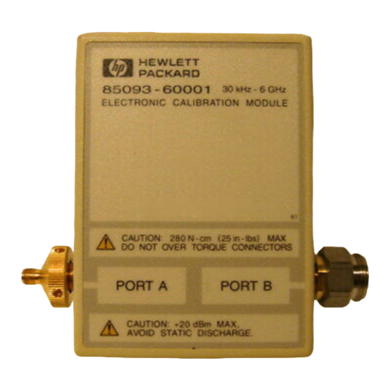
- Page 78 Description HP Part Number HP 85060B 1 GHz to 18 GHz Microwave ECal Module 85060-60002 HP 85091A 30 kHz to 6 GHz RF ECal Module (85060B Option 001) 85091-60001 Protective End Caps DB-25 Multi-pin Connector Cap 1252-4690 7 mm Connector Cap...
- Page 79 Replaceable Parts Figure 4-6 HP 85091A and HP 85060B Modules and Accessories Not Shown: Module Reference Guide, Storage Case, Specification/Verification Program Disk, Option 00F (female-to-female), and Option 00M (male-to-male). Chapter 4 4-13...
- Page 80 Replaceable Parts Table 4-7 Miscellaneous Other Supplies (not included) Description HP Part Number Cleaning Supplies Compressed Air 1 can 8500-6659 (235 ml) 99.5% Isopropyl Alcohol (8 oz) 8 oz 8500-0559 99.5% Isopropyl Alcohol (30 ml) 30 ml 8500-5344 Cleaning Swabs...
- Page 81 Index female 3-24 references to connector sex type-N connector 3-17 accuracy enhancement types 3-14 gauging type-F compatibility 3-27 electrostatic discharge barometric pressure handling and storage techniques 3-22 warranty 2-17 when 3-12 gauging devices 3-12 characteristics general information electrical 2-14 compatibility of connectors 3-27 zeroing the connector gauge 3-20...