
Related Manuals for Bosch FB 100


Summary of Contents for Bosch FB 100
- Page 1 Remote Control and Room Sensor FB 100 for FW 200 on a boiler with Heatronic 3 Installation and Operating Instructions...
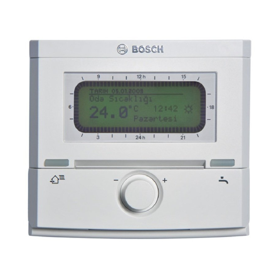
- Page 2 2 | Overview of controls and symbols US/CA Overview of controls and symbols menu info 6 720 643 256-01.1O Fig. 1 Standard display 6 720 643 259 (2010/05)
- Page 3 US/CA Overview of controls and symbols | 3 Controls Symbols Turning dial in + direction (clockwise): Current room temperature scrolls menu/information up or increases Flashing segment: setting value Time now (between 01:45pm and Turning dial in – direction (counter- 02:00pm) (13:45 - 14:00) clockwise): scrolls menu/information down or Solid segments: decreases setting value...
-
Page 4: Table Of Contents
4 | Contents US/CA Contents Explanation of symbols and safety MAIN MENU settings ....23 information ......7 MAIN MENU summary and settings 23 Explanation of symbols . - Page 5 US/CA Contents | 5 Troubleshooting ....42 Troubleshooting with display ..42 Troubleshooting without using display ....50 10 Energy saving tips .
-
Page 6: Explanation Of Symbols And Safety
6 | Information regarding the documentation US/CA Information regarding the documentation Guide to instructions Deliver all documentation enclosed to the user. If you ..are looking for the safety instructions and • an explanation of the symbols, refer to Section 1. -
Page 7: Information
US/CA Explanation of symbols and safety information | 7 Explanation of symbols and safety information Additional symbols Explanation of symbols Symbol Meaning Warnings Sequence of steps Warnings are indicated in the text Cross-reference to other points in by a warning triangle and a gray this document or to other background. -
Page 8: Safety Instructions
B Risk of scalding during thermal disinfection: Due to DHW temperatures occurring in excess of 140 °F (60 °C), Bosch strongly advises to install a DHW thermostatic mixing valve. B When there is a risk of frost, leave the boiler switched on and follow the frost protection information. -
Page 9: Information About The Appliance
The FB 100 can only be connected Scope of delivery to systems with FW 200 and a boiler with BUS-enabled Heatronic 3. The FB 100 is used to display device and • system information and to change the settings shown. -
Page 10: Installation Example
FW 200 Option A System 2 Option E Option C DWUC DWU1 FW 200 FB 100 FB 100 FB 100 IPM 2 IPM 2 Fig. 3 Schematic diagram of system (diagram for installation purposes included in the planning documents) 6 720 643 259 (2010/05) - Page 11 If Heating zone pump the FW 200 is installed in the boiler, a 1...4 Solar circuit pump (option A) FB 100 in the first heating zone is Circulation pump for thermal possible. disinfection Optional...
-
Page 12: Installation (For Installers Only)
12 | Installation (for installers only) US/CA Installation (for installers only) The detailed system diagram for mounting the Installation hydraulic components and the associated control The mounting surface on the wall devices can be found in the planning documents should be level. or specifications. -
Page 13: Disposal
US/CA Installation (for installers only) | 13 B Mount the base. 3 / 6 4 " Ø 2 2 m m ) ( Ø 6 0 9/64" 15/64" 15/64" 9/64" (3,5 mm) (6 mm) (6 mm) (3,5 mm) 6 720 643 250-03.1O Fig. -
Page 14: Making The Electrical Connections
TV devices, amateur radio stations, microwave devices, etc.). FB 100 6 720 613 571-05.1R Fig. 8 FB 100 connected to any BUS user (B). If the BUS cables feature different cross-sections: B Connect BUS link via a junction box. 6 720 643 259 (2010/05) -
Page 15: Commissioning (Installers Only)
B On commissioning, the automatic system configuration is started (wait 60 seconds and follow the instructions shown). B Set time and date for the FB 100 on the outdoor reset controls. B Adjust other settings to suit the specifics of... -
Page 16: Operation
16 | Operation US/CA Operation 5.1.2 Changing the operating mode (time- The FB 100 offers the option of limited) setting the desired room To change the operating mode permanently, temperature for the operating mode section 5.1.4 on page 17. concerned. This temperature entry is not the actual room temperature. -
Page 17: Changing The Domestic Hot Water Operating Mode (Time-Limited)
/ Economy / Frost according heating immediately (the activated function to the active heating program. The FB 100 cannot be switched off once activated). controls the room temperatures set on the – The DHW tank is heated up to the Heating levels submenu ( section 6.3.2 on... -
Page 18: Operation Of The Menus
18 | Operation US/CA Operation of the menus Principle of menu guidance: Arrows in the left margin indicate that there • are additional menu options. Variable names or submenu names are • displayed left-flush. A flashing variable value can be changed with •... - Page 19 US/CA Operation | 19 Operating Instructions Display Selecting the menu: Turn In this example, put the marking on the “Heating” menu option. Additional menus become visible if the dial is turned again. 6 720 643 262-09.1O Press Confirm selected menu option “Heating”. 6 720 643 262-12.1O Press In this example, put the marking on the “Program”...
- Page 20 6 720 643 256-19.1O Press Confirm the selected menu option The next menu up is displayed. Ending the programming: Press The FB 100 now works with the newly programmed data. menu 6 720 643 259-03.1O 6 720 643 259 (2010/05)
-
Page 21: Deleting Or Resetting Programming
US/CA Operation | 21 5.2.2 Deleting or resetting programming Operating Instructions Display Deleting programmed values: Select and overwrite the value to be deleted, for example the switch point in P1 as described in section 5.2.1 on page 18. -or- Press The deleted switch point flashes and the associated operating mode is also deleted. - Page 22 22 | Operation US/CA Operating Instructions Display Reset all settings (only for the installer): This function resets all settings on the MAIN MENU and the INSTALLER SETTINGS to their factory settings. Following such a reset, your installer will need to commission the system again! If the default display is set: menu Press...
-
Page 23: Main Menu Settings
US/CA MAIN MENU settings | 23 MAIN MENU settings Moving through menu structure, programming, deleting values and reverting to the default setting are described in detail in section 5.2 from page 18. MAIN MENU summary and settings The tables set out below provide references to the detailed descriptions of the •... -
Page 24: Main Menu: Heating
24 | MAIN MENU settings US/CA 6.1.2 MAIN MENU: Heating Default Personal Description Menu structure Heating setting Control range setting starts on page Program – – – Activate A:Program A A:Program A ...C:Program C – (switch points (program name can be changed) from Family program) Edit... -
Page 25: Main Menu: General Settings
US/CA MAIN MENU settings | 25 Default Personal Description Menu structure Heating setting Control range setting starts on page Parameter – – – Heating levels – – – Comfort 70 °F 32 °F ... 86 °F (0 °C ... 30 °C) °F ( °C) (21.0 °C) (not lower than Economy) -
Page 26: Vacation Program
26 | MAIN MENU settings US/CA Vacation program Main menu: Vacation For menu structure and adjustment ranges page 23. Use this menu if you want special operation for several days without changing the personal settings of the individual programs and parameters. -
Page 27: Heating Program
US/CA MAIN MENU settings | 27 Heating program Main menu: Heating Menu: Heating > Program > Edit For menu structure and adjustment ranges Setting options: page 24. A maximum six switch points per day with • three different operating modes (Comfort / Economy / Frost Set the supply temperature control... -
Page 28: Temperature For The Operating Modes And Heat-Up Rate
6.3.2 Temperature for the operating modes and heat-up rate Menu: Heating > Parameter The FB 100 has no settings for a DHW program, Use this menu to permanently set the program for the recirculation pump, parameters temperature levels for the 3 operating modes for DHW and thermal disinfection for a DHW tank. -
Page 29: General Settings
US/CA MAIN MENU settings | 29 General settings Main menu: General settings 6.5.2 Button lock For menu structure and adjustment ranges Menu: General settings > Key lock page 25. Use this menu if you want to prevent 6.5.1 Display formats unauthorized use of the button functions, e.g. -
Page 30: Viewing Information
30 | Viewing information US/CA Viewing information Menu: INFO INFO menu overview The table below provides This menu allows you to view a variety of system an overview of the menu structure (column 1). information. • The menu depth is identified by various Detailed instructions on navigating through the shades of gray. - Page 31 Desired room temperature for the assigned heating circuit (only if “Room influence” is active). Current room temperature 71.6 °F (22.0 °C) Room temperature measured on the FB 100. Desired heating supply 167.0 °F (75.0 °C) Supply temperature calculated and required by the temperature FB 100 for the assigned heating circuit.
-
Page 32: Menu Settings Installer Settings (For Installers Only)
32 | Menu settings INSTALLER SETTINGS (for installers only) US/CA Menu settings INSTALLER SETTINGS (for installers only) references to the detailed descriptions of the • The INSTALLER SETTINGS menu is individual menu options (column 5). intended only for installers. To open INSTALLER SETTINGS: The menu options are only shown if menu press and hold... -
Page 33: Installer Settings: Heating Parameters
US/CA Menu settings INSTALLER SETTINGS (for installers only) | 33 8.1.2 INSTALLER SETTINGS: Heating parameters Menu structure Default Personal Description Heating parameters setting Control range setting starts on page Heating circuit type Radiators Baseline/Design temp | Radiant Floor | Radiators | Baseboard Base line 78 °F (25 °C) 50 °F ... -
Page 34: Cust Service Address
Boiler date of manufacture 06/27/2010 – – (data from boiler) Controller part number and 7 777 777 777 – – model FB 100 (fixed factory setting) Controller date of manufacture 06/27/2010 – – (fixed factory setting) Controller software version JF11.12 (fixed –... -
Page 35: Configuring The Heating System
US/CA Menu settings INSTALLER SETTINGS (for installers only) | 35 Configuring the heating system Parameters for heating Installer settings: System configuration Installer settings: Heating parameters For menu structure and adjustment ranges For menu structure and adjustment ranges page 32. page 33. For system examples, see the Set the supply temperature control instructions for the IPM. - Page 36 36 | Menu settings INSTALLER SETTINGS (for installers only) US/CA °F °C °F °C -4 °F -4 °F -20 °C -20 °C 6 720 643 250-09.1O 6 720 643 250-11.1O Fig. 11 Factory setting of heating curve for base Fig. 13 Factory setting for heating curve in point/end point radiator heating system...
- Page 37 US/CA Menu settings INSTALLER SETTINGS (for installers only) | 37 Factory setting of parameters for Baseline/Design heating curve temp Radiant Floor Radiators Baseboard Heating surface exponent (fixed – value), curvature of heating curve Minimum outdoor temperature – 6 °F ( – 15 °C) 6 °F ( –...
- Page 38 38 | Menu settings INSTALLER SETTINGS (for installers only) US/CA Menu: Heating parameters > Room temperature Menu: Heating parameters > Risk of freezing at offset outdoor temperature B Set the permanent increase in the desired WARNING: Domestic hot water room temperature for the assigned heating pipework may freeze during longer circuit, e.g.
- Page 39 3). B Position a precision instrument near the A low outdoor temperature produces a flat FB 100. The precision instrument must not heating curve. transfer any heat to the FB 100. B Keep away from heat sources such as sunlight,...
-
Page 40: Solar Settings
(fault sense to reduce the supply temperature that is date, source, code and description). The faults required by the boiler. With the FB 100, this shown first may still be active. reduction can be carried out automatically with Heating circuit solar optimization depending on the availability of solar energy. -
Page 41: Viewing System Information
US/CA Menu settings INSTALLER SETTINGS (for installers only) | 41 Viewing system information Test of the actuators on the system Installer settings: System info Menu structure page 34. INSTALLER SETTINGS: Output test For menu structure and adjustment range Shows a variety of system information: page 34. -
Page 42: Troubleshooting
42 | Troubleshooting US/CA Troubleshooting BUS device faults are indicated. A boiler fault (e.g. EA fault) is shown in the remote control display with the relevant note texts. B Notify your installer. For the installer: B Remove the fault in accordance with the details in the boiler documentation. - Page 43 Remedy (by installer) Fault 01 BUS device assigned to the Check BUS device, BUS BUS communication fault. IPM FB 100 no longer answers. connection and repair Boiler no longer reporting. disconnect if necessary. Incorrect BUS device Identify and replace incorrect connected.
- Page 44 44 | Troubleshooting US/CA Display ( Item 1, 3 and 4 in fig. 15 Text Code Cause Remedy (by installer) Fault 11 New ISM detected on the Power up all ISMs System configuration: new bus device controls. simultaneously and start automatic system configuration on the controls.
- Page 45 US/CA Troubleshooting | 45 Display ( Item 1, 3 and 4 in fig. 15 Text Code Cause Remedy (by installer) Fault 19 BUS device is configured but Check system layout, check Unable to save parameter settings not available at present. system configuration, modify if necessary and set parameter again.
- Page 46 46 | Troubleshooting US/CA Display ( Item 1, 3 and 4 in fig. 15 Text Code Cause Remedy (by installer) Fault 32 Tank temperature sensor (SF) Check storage tank Tank temperature sensor defective connected to IPM defective. temperature sensor (SF) and replace if required.
- Page 47 US/CA Troubleshooting | 47 Display ( Item 1, 3 and 4 in fig. 15 Text Code Cause Remedy (by installer) Fault 49 Short circuit on the sensor Check temperature sensor Temperature sensor TD on external heat lead (TD). (TD) and replace if necessary. Break in sensor lead (TD).
- Page 48 48 | Troubleshooting US/CA Display ( Item 1, 3 and 4 in fig. 15 Text Code Cause Remedy (by installer) Fault 52 Temperature sensors (T Check the temperature Temperature sensors reversed ) reversed. sensors and swap the Temperature sensors (TA and connections if necessary.
- Page 49 US/CA Troubleshooting | 49 Display ( Item 1, 3 and 4 in fig. 15 Text Code Cause Remedy (by installer) Fault 56 Pump (SP) in manual mode. Reset parameters for pump or At least one pump/valve in manual mode Valve (DWU1) in manual mode. valve to “Auto”.
-
Page 50: Troubleshooting Without Using Display
Installation site of FB 100 unfavorable, Select a better location for FB 100 and e.g. external wall, close to window, in a ask your installer to reposition it. draft, ... - Page 51 US/CA Troubleshooting | 51 If the fault persists: B Call the authorized installer or customer service and inform them of the fault, quoting the controller details (from the identification plate inside the flap). Appliance details Type: ................Order number: ................Date of manufacture (FD...): ................
-
Page 52: Energy Saving Tips
52 | Energy saving tips US/CA 10 Energy saving tips With outdoor reset controls, the supply Good thermal insulation of the building: the • • temperature is controlled in accordance with set temperature for Economy is never the set heating curve: The colder the outdoor reached. -
Page 53: Environmental Protection
US/CA Environmental protection | 53 11 Environmental protection Environmental protection is one of the fundamental company policies of the Bosch Group. We regard quality of performance, economy and environmental protection as equal objectives. Environmental protection laws and regulations are strictly adhered to. -
Page 54: Individual Settings For The Heating Program
54 | Individual settings for the heating program US/CA 12 Individual settings for the heating program The default settings and personal settings for the set the heating program is described in timer programs are summarized below. How to section 6.3 on page 27. Monday - 06:00am 08:00am... - Page 55 US/CA Individual settings for the heating program | 55 Monday - 06:00am 10:00pm – – – – – – – – Thursday Friday 06:00am 11:30pm – – – – – – – – Saturday 07:00am 11:30pm – – – – –...
- Page 56 56 | Individual settings for the heating program US/CA All days Mon - Fri Sat + Sun Monday Tuesday Wednesday Thursday Friday Saturday Sunday 6 720 643 259 (2010/05)
-
Page 57: Index
Initial test ............41 Installation Default settings ..........32 - Accessories ..........13 Deleting ............21 - FB 100 ............12 Details about the device Installer settings ..........32 - Scope of delivery ..........9 - Customer service address ....34, 40 - Technical specifications .......9 - Fault history ......... - Page 58 58 | Index US/CA Main menu Packaging ............53 - General settings .........25 Panel radiator ..........52 - Heating ............24 Power module IPM 2 (accessory) ....11 - Vacation ............23 Programming Making the electrical connections ....14 - Deleting ............. 21 Menu - Installer settings ........
- Page 59 US/CA Index | 59 Technical specifications ........9 Test - Actuators ............41 - Outputs for pumps and mixing valve ..41 Thermostats ............52 Timer (see heating program) ......17 Times for DHW heating ........28 Troubleshooting ..........42 Vacation program ........23, 26 Venting ............52 Warmer - DHW ............28 - Heating ............16 6 720 643 259 (2010/05)
- Page 60 50 Wentworth Avenue Londonderry, NH 03053 Tel. 603-552-1100 Fax 603-584-1681 www.bosch.us U.S.A. Products manufactured by Bosch Thermotechnik GmbH Junkersstrasse 20-24 D-73249 Wernau www.bosch-thermotechnology.com Bosch Thermotechnology Corp. reserves the right to make changes without notice due to continuing engineering and technological advances. 067206432592...