
Related Manuals for Bosch DINION imager 9000 HD


Summary of Contents for Bosch DINION imager 9000 HD
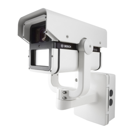
- Page 1 DINION imager 9000 HD NAI-90022 Installation Manual Available from A1 Security Cameras www.a1securitycameras.com email: sales@a1securitycameras.com...
- Page 2 Available from A1 Security Cameras www.a1securitycameras.com email: sales@a1securitycameras.com...
-
Page 3: Table Of Contents
DINION imager 9000 HD Table of Contents | en Table of Contents Safety Safety precautions Important safety instructions Important notices FCC & ICES compliance FCC Information CSA certification - Disclaimer Planning Pre-installation Checklist Installation Overview of Installation Steps Select Tilt and Width of Illumination Beam 3.2.1... -
Page 4: Safety
| Safety DINION imager 9000 HD Safety Safety precautions DANGER! High risk: This symbol indicates an imminently hazardous situation such as “Dangerous Voltage” inside the product. If not avoided, this will result in an electrical shock, serious bodily injury, or death. -
Page 5: Important Notices
DINION imager 9000 HD Safety | en Protect the power cord from being walked on or pinched particularly at plugs, convenience receptacles, and the power where they exit from the apparatus. Use only attachments/accessories specified by the manufacturer. Refer all servicing to qualified service personnel. Servicing... - Page 6 | Safety DINION imager 9000 HD CAUTION! This product has been tested according to standard CIE/IEC 62471:2006 “Photobiological safety of lamps and lamp systems” and found to meet Risk Group 2 for exposure limit 4.3.7 “Infrared radiation hazard exposure limits for the eye.”...
- Page 7 Electronic Surveillance - This device is intended for use in public areas only. U.S. federal law strictly prohibits surreptitious recording of oral communications. Environmental statement - Bosch has a strong commitment towards the environment. This unit has been designed to respect the environment as much as possible.
-
Page 8: Fcc & Ices Compliance
Network Voltage (TNV) circuits. Video loss - Video loss is inherent to digital video recording; therefore, Bosch Security Systems cannot be held liable for any damage that results from missing video information. To minimize the risk of lost digital information, Bosch Security Systems recommends multiple, redundant recording systems, and a procedure to back up all analog and digital information. -
Page 9: Fcc Information
DINION imager 9000 HD Safety | en to radio or television reception, which can be determined by turning the equipment off and on, the user is encouraged to try to correct the interference by one or more of the following measures: –... -
Page 10: Csa Certification - Disclaimer
| Safety DINION imager 9000 HD interférences nuisibles au niveau des radiocommunications. Toutefois, rien ne garantit l'absence d'interférences dans une installation particulière. Il est possible de déterminer la production d'interférences en mettant l'appareil successivement hors et sous tension, tout en contrôlant la réception radio ou télévision. - Page 11 PERFORMANCE OR RELIABILITY OF ANY SECURITY OR SIGNALING RELATED FUNCTIONS OF THIS PRODUCT. Bosch notices Copyright This manual is the intellectual property of Bosch Security Systems and is protected by copyright. All rights reserved. Trademarks All hardware and software product names used in this document are likely to be registered trademarks and must be treated accordingly.
-
Page 12: Planning
Verify that all the parts listed in the Parts List below are included. If any items are missing, notify your Bosch Security Systems Sales or Customer Service Representative. The original packing carton is the safest container in which to transport the unit and must be used if returning the unit for service. - Page 13 DINION imager 9000 HD Planning | en Required Tools (User-supplied) – 2.5 mm (0.1 in.) straight-blade screwdriver – Socket wrench; 14 mm (9/16 in.) socket – Drill; 5.5 mm (7/32 in.) drill bit WARNING! Important mounting instructions This apparatus must be securely attached to the wall in accordance with these installation instructions.
-
Page 14: Pre-Installation Checklist
| Planning DINION imager 9000 HD Pre-installation Checklist WARNING! This installation must be made by a qualified service person and must conform to all local codes. WARNING! CSA Certified / UL Listed CLASS 2 (or Certified PoE+ rated 42.5 VDC to 57 VDC, 600 mA, 34.20 W (max), for IP models) power adapters must be used in order to comply with electrical safety standards. - Page 15 DINION imager 9000 HD Planning | en Route all rough wiring including: power, audio, ethernet, and alarms I/O. Select the appropriate mounting kit to use depending on the location of the camera. The camera is intended to be mounted securely to a wall using the mounting holes in the junction box.
-
Page 16: Installation
| Installation DINION imager 9000 HD Installation CAUTION! Installation must be made by qualified service personnel and must conform to the National Electrical Code and all applicable local codes. WARNING! IMPORTANT MOUNTING INSTRUCTIONS The camera must be attached securely to the wall in accordance with these installation instructions. -
Page 17: Select Tilt And Width Of Illumination Beam
DINION imager 9000 HD Installation | en Select Tilt and Width of Illumination Beam Before mounting the camera decide the application: – As a general guideline, the IR LED tilt angle should be raised above the axis of the camera to reduce overexposure in the foreground. -
Page 18: Changing The Angle Of Ir Led Tilt
| Installation DINION imager 9000 HD 3.2.1 Changing the angle of IR LED tilt NOTICE! Do not discard the additional LED tilt set screw supplied. It may be required to adjust the angle of LED tilt. Unscrew the current tilt screw located between the camera window and the IR LED window at the front of the camera. -
Page 19: Inserting The 3D Diffuser
DINION imager 9000 HD Installation | en 3.2.2 Inserting the 3D diffuser Unscrew the four captive screws beneath the illuminator at the front of the unit (item 2). Figure 3.2 3D Diffuser Using the captive screws, remove the 3D diffuser holder. -
Page 20: Unattach Junction Box
| Installation DINION imager 9000 HD Unattach Junction Box Before mounting the junction box, remove it from the camera assembly. Use an allen key to loosen the two screws and open the junction box. Loosen the slotted screws of the input/ output terminal block (7-pin) and the slotted screws of the power terminal block (2-pins). -
Page 21: Mount The Junction Box
DINION imager 9000 HD Installation | en Mount the Junction Box Figure 3.4 Interior of the Junction Box Decide which holes in the junction box to use to insert the cables: the holes in the bottom of the box, the holes in the back of the box, or the holes in the side of the box. -
Page 22: Route Wires And Attach Connectors
| Installation DINION imager 9000 HD NOTICE! You must use the appropriate UL-listed / NPS watertight conduits and fittings to ensure that water cannot enter the junction box. – Use 20 mm (3/4 in.) NPS fittings for the holes on the bottom and back of the box. -
Page 23: Input/Output Connections
DINION imager 9000 HD Installation | en 3.5.1 Input/Output Connections Figure 3.5 Terminal Block for Input/Output Connections # Label Description Wire Color 1 NC Not connected 2 V1 Alarm output 2 Yellow 3 V2 Alarm output 1 White 4 T1... -
Page 24: Attach Camera To Junction Box
| Installation DINION imager 9000 HD Attach Camera to Junction Box The bottom hinge pin of the camera arm has a stop to hold the hinge open while attaching the arm to the junction box. DANGER! Serious injury or death can occur if the hinge pins of the camera arm are not fully engaged (locked) to the junction box. - Page 25 DINION imager 9000 HD Installation | en then release the bottom hinge pin from the hinge pin stop to lock the camera arm to the junction box. Put the input/output terminal block on the bracket and tighten the two slotted screws.
-
Page 26: Camera Set-Up
| Camera Set-up DINION imager 9000 HD Camera Set-up Configuration of the camera is carried out via the network using a web browser. Use the browser to configure the camera settings, including lens zoom/ focus and IR LED power intensity. -
Page 27: Control Panel
DINION imager 9000 HD Camera Set-up | en 4.1.2 Control panel Controls and sockets are located behind the access panel at the rear of the camera housing. micro SD Menu Reset TV out 1. MicroSD card slot Insert a microSD card into the slot. -
Page 28: Camera Positioning And Field-Of-View
| Camera Set-up DINION imager 9000 HD Camera positioning and field-of-view To help position the camera and set the field-of-view: Connect a monitor to the 2.5 mm jack using the optional monitor cable (S1460) which provides a CVBS signal (for installation purposes only). - Page 29 DINION imager 9000 HD Camera Set-up | en Figure 4.2 Example orientation: Camera rotated 90 degrees left, pointing up 44 degrees. From left: front view, side view, back view Figure 4.3 Example orientation: Camera rotated 90 degrees right, point ing down 48 degrees. From left: front view, side view, back view...
-
Page 30: Using The Install Wizard
| Camera Set-up DINION imager 9000 HD 4.3 Using the install wizard The Menu button on the control panel is used to access the camera install wizard. When there is a choice in the wizard, the options are selected by either a short press (less than 2 s) or a long press (more than 2 s) of the button. -
Page 31: Am18-Q0663 | 1.0 | 2013.09
DINION imager 9000 HD Camera Set-up | en To rotate the image 180°, press and hold the Menu button until the image flips. Briefly press the Menu button to open the automatic motorized focus adjustment screen. Briefly press the Menu button to set the focus and zoom defaults. - Page 32 Bosch Security Systems www.boschsecurity.com © Bosch Security Systems, 2013 Available from A1 Security Cameras www.a1securitycameras.com email: sales@a1securitycameras.com...