Table of Contents
Advertisement
Quick Links
PSB modules
SIMATIC
EMS400S
PSB modules
Operating Instructions
03/2014
A5E03474166-03
___________________
Preface
___________________
Overview
Description of the PSB
___________________
module functions
___________________
Safety instructions
Installing and wiring PSB
___________________
module
___________________
Displays and address ranges
Data processing plant
segment controller – carrier
controller
Creating and transmitting
___________________
projects
Diagnostics options for PSB
___________________
modules
___________________
Maintenance and repairs
___________________
Technical specifications
___________________
Appendix
1
2
3
4
5
6
7
8
9
10
A
Advertisement
Table of Contents

Related Manuals for Siemens SIMATIC EMS400S PSB-S


Summary of Contents for Siemens SIMATIC EMS400S PSB-S
- Page 1 ___________________ PSB modules Preface ___________________ Overview Description of the PSB ___________________ module functions SIMATIC ___________________ Safety instructions EMS400S Installing and wiring PSB ___________________ PSB modules module ___________________ Displays and address ranges Operating Instructions Data processing plant segment controller – carrier controller Creating and transmitting ___________________...
- Page 2 Note the following: WARNING Siemens products may only be used for the applications described in the catalog and in the relevant technical documentation. If products and components from other manufacturers are used, these must be recommended or approved by Siemens. Proper transport, storage, installation, assembly, commissioning, operation and maintenance are required to ensure that the products operate safely and without any problems.
-
Page 3: Preface
Pay particular attention to section "Safety instructions (Page 15)". Scope of documentation The following documents provide a full description of the "EMS400S Plant controller for Electrical Monorail Systems": The documents in the figure are available at: EMS400S product documentation (http://support.automation.siemens.com/WW/view/en/68156412/133300) PSB modules Operating Instructions, 03/2014, A5E03474166-03... - Page 4 The documents contain links to other relevant documents for Siemens standard modules that are used for the EMS. The "S7-1200 Automation System" System Manual for the SIMATIC-S7 CPU is of ultimate importance in this context.
- Page 5 Preface Style conventions Style Convention Scope "Add screen" Terminology for the user interface, e.g. dialog name, tab, • button, menu command Necessary entries, e.g. limit value, tag value • Path information • "File > Edit" Operational sequences, e.g, menu command, shortcut menu command You should also observe notes that are marked as follows: Note...
- Page 6 Preface PSB modules Operating Instructions, 03/2014, A5E03474166-03...
-
Page 7: Table Of Contents
Table of contents Preface ..............................3 Overview..............................9 Product overview..........................9 System limits ..........................10 Scope of delivery.......................... 10 Description of the PSB module functions ....................11 Description of the PSB-S module functions ................. 11 Description of the PSB-C module functions ................. 12 Data flow between the PSB modules .................. - Page 8 Table of contents Creating and transmitting projects ......................43 Creating a project in the TIA Portal ..................... 43 Transferring the project ....................... 46 Commissioning a project ......................46 Diagnostics options for PSB modules ....................47 Diagnostics in STEP 7 ........................ 47 Messages and errors ........................
-
Page 9: Overview
Overview Product overview The PSB modules are conceived for an EMS that is equipped with the EMS400S plant controller. Operating in combination with an S7-1200 CPU, the PSB modules act as a plant segment controller and carrier controller. Communication in the EMS is handled by the "PSB-S modules" and "PSB-C modules". These modules set up the connection for communication between the stationary and mobile sections of the unit. -
Page 10: System Limits
Overview 1.2 System limits System limits The following applies to PSB-S and PSB-C modules: ● PSB-S module – PSB-C module communication The communication between the plant segment controller and carrier controller and thus between PSB-S and PSB-C module is based on the following parameters. Parameter Value Comment... -
Page 11: Description Of The Psb Module Functions
Description of the PSB module functions Description of the PSB-S module functions The following figure provides an overview of the components that can be connected to the PSB-S module. Data transmission on RAIL 1 to RAIL 3 can be configured for specific plant segments in the TIA Portal. -
Page 12: Description Of The Psb-C Module Functions
Description of the PSB module functions 2.2 Description of the PSB-C module functions A description of the interfaces is provided in the section "Interfaces of the PSB-S module (Page 62)", while the LED functions are specified in the section "LED display on the PSB-S module (Page 29)". -
Page 13: Data Flow Between The Psb Modules
Description of the PSB module functions 2.3 Data flow between the PSB modules Data flow between the PSB modules The following figure demonstrates the principles of data flow for the synchronization signal and communication between the controllers of the EMS. ①... - Page 14 Description of the PSB module functions 2.3 Data flow between the PSB modules PSB modules Operating Instructions, 03/2014, A5E03474166-03...
-
Page 15: Safety Instructions
Safety instructions WARNING Injury or material damage You risk the development of danger sources and deactivation of safety functions if you neglect the safety and handling instructions provided in this document. This can result in personal injuries or material damage. Strictly adhere to the safety and handling instructions. - Page 16 The safety concept for overvoltage protection described in this section has been tested and approved by TÜV SÜD. You can find the technical report of the TÜV SÜD in the Internet under entry ID 134200 (http://support.automation.siemens.com/WW/view/en/68156412/134200). The documents belonging to the EMS400S plant controller are listed in the preface. Note High-frequency radiation, e.g.
- Page 17 Safety instructions Note Observe the following points: • The safety regulations must be applied in the aforementioned order before any work is carried out on electrical systems. The safety regulations must be applied in reverse order on completion of all tasks on the electrical system. •...
- Page 18 Safety instructions PSB modules Operating Instructions, 03/2014, A5E03474166-03...
-
Page 19: Installing And Wiring Psb Module
Note You risk malfunctions if using faulty parts that have were delivered to you. Always use part that do not disclose any fault. Contact your Siemens partner for support for faulty parts. Determining the installation location and clearances The mounting, mounting position and clearances of the PSB modules are specified in chapter "Installation"... -
Page 20: Dc Power Supply Requirements
(Page 72)". 48 V DC power supply requirements The PSB-S module is operated on 48 V DC. Only the LOGO!Power modules of Siemens AG with order number 6EP1332-1SH52 are approved for supplying power. These modules must be wired in series. Additional information is available in the section "Interfaces of the PSB-S module (Page 62)". -
Page 21: Installing The Psb Module
Installing and wiring PSB module 4.4 Installing the PSB module Overvoltage category The PSB module is compliant with overvoltage category II to EN 61010-1. Keep this overvoltage category in mind during system configuration. Installing the PSB module 4.4.1 Overview Note Components may only be installed or removed while the power supply is shut down. -
Page 22: Control Elements
Installing and wiring PSB module 4.4 Installing the PSB module 4.4.2 Control elements The PSB module is equipped with the following control elements: ① Contact cover, top ② Upper latch ③ SM bus slide ④ SM bus cover ⑤ Contact cover, bottom Procedure 1. -
Page 23: Fastening The Psb Module With Screws
Installing and wiring PSB module 4.4 Installing the PSB module 4.4.3 Fastening the PSB module with screws Requirement ● Two M4 cylindrical head screws, with nuts if required. ● A suitable mounting position was selected for the corresponding CPU in accordance with chapter "Determining the installation location and clearances (Page 19)". -
Page 24: Installing The Psb Module On A Mounting Rail
Installing and wiring PSB module 4.4 Installing the PSB module Removal 1. Move the SM bus slide inside the housing. 2. Loosen the cylindrical head screws. Secure the PSB module to prevent it from dropping down. 4.4.4 Installing the PSB module on a mounting rail The PSB-S module can typically be fastened to a mounting rail. - Page 25 Installing and wiring PSB module 4.4 Installing the PSB module Procedure Removal 1. Press down on the slide and push it in direction of the arrow until you hear a clicking noise indicating that the slide has reached its final position.
-
Page 26: Wiring Psb Modules
Installing and wiring PSB module 4.5 Wiring PSB modules Wiring PSB modules 4.5.1 Wiring information Note Observe the following points: • Safety instructions Observe the safety instructions in the "EMS400S carrier controller for EMS plants" system manual. • Device failure Moisture and condensation lead to malfunction. -
Page 27: Wiring The Power And Data Cables
Installing and wiring PSB module 4.5 Wiring PSB modules 4.5.2 Wiring the power and data cables The PSB modules are equipped with terminal blocks for wiring the power and data cables. The terminal block assignments are specified in the section "Interface description (Page 62)". -
Page 28: Securing The Cables
Installing and wiring PSB module 4.6 Securing the cables NOTICE Communication failure of PSB-S modules in case of polarity reversal The polarity reversal of the 48 V connectors of a PSB-S module may result in the communication failure of several PSB S modules during travel. Ensure the correct polarity. -
Page 29: Displays And Address Ranges
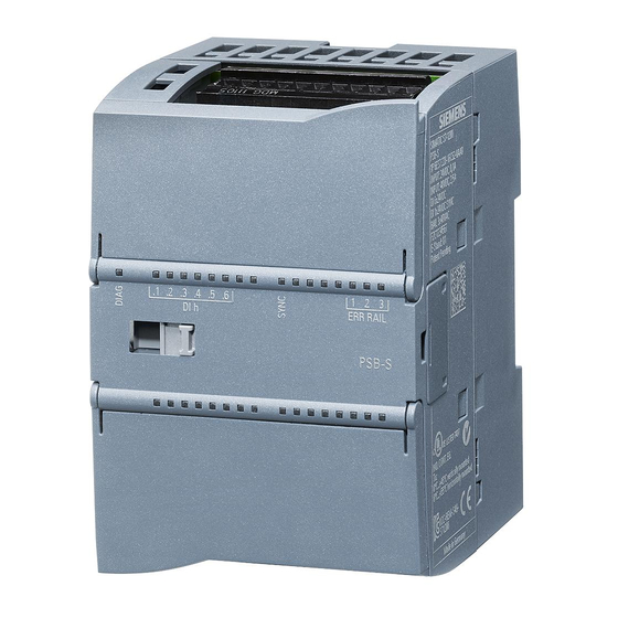
The following "EMS400S" functions blocks are available for providing this data. For more information, refer to: EMS400S product documentation (http://support.automation.siemens.com/WW/view/en/68156412/133300) Plant segment controller A segment controller consists of an S7-1200 CPU and up to eight PSB-S modules. 5.2.1 LED display on the PSB-S module The PSB-S module is equipped with two LED displays. - Page 30 Displays and address ranges 5.2 Plant segment controller Meaning of the labeled LEDs: Status Meaning DIAG Green, on The PSB-S module ready for operation, or the program is running Green, The PSB-S module is not configured, is in startup mode or a •...
- Page 31 Displays and address ranges 5.2 Plant segment controller Status Meaning ERR RAIL 2 At least one error in the plant segment n + 1 • No data transmission from the EMS carrier to the plant segment • controller via RAIL 2 Error in data transmission from the EMS carrier to the plant segment •...
-
Page 32: Address Ranges Of The Psb-S Module
Displays and address ranges 5.2 Plant segment controller 5.2.2 Address ranges of the PSB-S module NOTICE Malfunction 8 bytes are reserved in the I/O address space of the PSB-S module for the EMS400S function blocks. These 8 bytes are managed by the EMS400S function blocks. You risk malfunctions if using these 8 bytes for other data Do not use the reserved area. - Page 33 Displays and address ranges 5.2 Plant segment controller The input address space comprises 8 bytes. Word Byte Name Description Terminals 0, 1 – Data from plant segment n The data has a length of one RAIL 1 word 2, 3 –...
-
Page 34: Carrier Control
Displays and address ranges 5.3 Carrier control The output address space comprises 8 bytes. Word Byte Name Description Terminals 0, 1 – Data transmitted to the carrier The data has a length of RAIL 1 controller in plant segment n one word 2, 3 –... -
Page 35: Led Display On The Psb-C Module
Displays and address ranges 5.3 Carrier control 5.3.1 LED display on the PSB-C module The PSB-C module is equipped with two LED displays. The upper LED display is used for signaling. The lower LED has no function. Meaning of the labeled LEDs: Display Meaning DIAG... -
Page 36: Address Ranges Of The Psb-C Module
Displays and address ranges 5.3 Carrier control Display Meaning The display unit is not connected. • DISP Error in communication between the PSB-C module and the display • unit Firmware of the PSB-C module is incompatible with the firmware of the •... - Page 37 Displays and address ranges 5.3 Carrier control The input address space comprises 8 bytes. Word Byte Name Description Terminals 0, 1 – Data from the plant The data has a length of one RAIL segment controller word 2, 3 – Reserved –...
- Page 38 Displays and address ranges 5.3 Carrier control Word Byte Name Description Terminals Validation bit 0 = invalid or superimposed RAIL data, or error 1 = valid, current data – Toggle between "data to acknowledge" and "data not to acknowledge" ACK bit 0 = data not to acknowledge RAIL 1 = data to acknowledge...
- Page 39 Displays and address ranges 5.3 Carrier control Output address space The output address space of the PSB-C module is used to map data that is transmitted to the plant segment controller, to the display unit and to the analog output. The interfaces are specified in the section "Interfaces of the PSB-C module (Page 64)".
- Page 40 Displays and address ranges 5.3 Carrier control Word Byte Name Description Terminals Dot of 7-segment display 3 7-segment displays On/Off 7-segment displays 0 = off 1 = on Validation bit 0 = invalid data, or error RAIL 1 = valid, current data Enable bit 0 = disabled RAIL...
-
Page 41: Data Processing Plant Segment Controller - Carrier Controller
Data processing plant segment controller – carrier controller Duration of processing The time it takes to process the data is made up of the duration of internal processing on the controller and duration of the transmission of this data on the corresponding communication connections. - Page 42 Data processing plant segment controller – carrier controller OB1 cycle time When creating the EMS project, observe the following information to ensure the proper response of the system: The longer the OB1 cycle is, the higher the probability that the time available for the data subframe will be exceeded.
-
Page 43: Creating And Transmitting Projects
Requirement ● The configuration software is installed on the configuration computer ● The add-on "Siemens TIA Portal Vxx EHB AddOn - S7-1200 PSB" is installed "Vxx" stands for the installed version of the TIA Portal software. ● The TIA Portal is open. - Page 44 Creating and transmitting projects 7.1 Creating a project in the TIA Portal Procedure 1. Create a project in the TIA Portal. 2. Configure a CPU for a plant segment controller in the "Devices" editor. 3. Insert the required number of PSB-S modules from the hardware catalog. The following figure shows the resultant modification of the device view.
- Page 45 Creating and transmitting projects 7.1 Creating a project in the TIA Portal 5. Insert a PSB-C module from the hardware catalog. The following figure shows the resultant modification of the device view. This view is valid as of TIA Portal V13. ①...
-
Page 46: Transferring The Project
Creating and transmitting projects 7.2 Transferring the project Transferring the project It is prerequisite for operation of the plant segment or carrier control to provide a project in the corresponding CPU. The following routes are available for transmission of a project to the segment controller or carrier controller: ●... -
Page 47: Diagnostics Options For Psb Modules
Diagnostics options for PSB modules The following diagnostics options are available for the PSB modules: ● Diagnostics in STEP 7 You can run the diagnostics online in the network and device view, and with the help of the diagnostic buffer of the CPU. ●... -
Page 48: Messages And Errors
2. Select "Work area" Diagnostics > Diagnostic buffer in the window. The "Diagnostic buffer" window displays all events, including their details. For more information, refer to: "S7-1200 Automation System" system manual (http://support.automation.siemens.com/WW/view/de/36932465/0/en) Messages and errors The PSB module transmits a diagnostics interrupt request to the PU in the following situations: ●... -
Page 49: List Of Diagnostic Entries
Diagnostics options for PSB modules 8.2 Messages and errors 8.2.2 List of diagnostic entries The following section lists the events that trigger an entry in the diagnostic buffer of a PSB module. ● Single error in the STEP-7 diagnostic buffer Diagnostic entry Description Low voltage... - Page 50 Unknown error 000B Plant segment controller • Check whether the 48 V input voltage is present. If yes, the PBS-S module has failed. Return the PSB-S module to Siemens for repairs. Carrier controller • Check whether the 24 V input voltage is present. If yes, the PBS-C module has failed.
-
Page 51: Power Supply Fault
Diagnostics options for PSB modules 8.2 Messages and errors 8.2.3 Power supply fault. The following table contains a selection of possible errors. You can see how these errors are displayed and what you have to do to rectify the error. Error Diagnostics event 48 V input voltage is missing... -
Page 52: Diagnostics Via S7-1200 Web Server
The contents of the Web pages and user program data are linked by means of AWP commands that you insert into the HTML code. For more information about these options, refer to: System manual (http://support.automation.siemens.com/WW/view/de/36932465/0/en), chapter "Web server". Diagnostics by means of EMS400S function blocks The diagnostics options provided by the function blocks are specified in the "EMS400S... -
Page 53: Maintenance And Repairs
The PSB-S and PSB-C modules are maintenance-free. Repairs You must return the respective device for repairs to the Retouren-Center Fürth . Only the Retouren-Center Fürth is allowed to repair the device. The address is: Siemens AG Sektor Industry Retouren-Center Siemensstr. 2 90766 Fürth... - Page 54 Maintenance and repairs PSB modules Operating Instructions, 03/2014, A5E03474166-03...
-
Page 55: Technical Specifications
Technical specifications 10.1 Dimensional drawings Additional images are available on the Internet at: Image database (http://www.automation.siemens.com/bilddb) PSB modules Operating Instructions, 03/2014, A5E03474166-03... -
Page 56: Technical Specifications
Technical specifications 10.2 Technical specifications 10.2 Technical specifications 10.2.1 PSB-S module Mechanical system Parameter Value Order number 6ES7228-1RC52-0AA0 Dimensions (W × H × D) 70 × 100 × 75 mm Weight 230 g 24 V DC power supply Parameter Value Rated voltage 24 V DC Voltage range... - Page 57 Technical specifications 10.2 Technical specifications 48 V DC power supply Parameter Value Rated voltage 48 V DC Voltage range 45.6 to 50.4 V DC Continuous voltage DC ≤ 50.4 V Supply interruption Interruption not permitted Current consumption 2.2 A Power loss Overvoltage category Transient voltage V ≤...
- Page 58 Technical specifications 10.2 Technical specifications SYNC input Parameter Value Number of inputs Type Current sinking, IEC type 1 Rated voltage 24 V DC Continuous voltage, permitted DC ≤ 30 V Surge voltage 35 V DC for 0.5 s Signal logical 1 DC ≥...
-
Page 59: Psb-C Module
Technical specifications 10.2 Technical specifications Protection class and degree of protection Characteristic Standard Classification Protection class EN 61131-2 Degree of protection II Degree of protection EN 60529 IP20 10.2.2 PSB-C module Mechanical system Parameter Value Order number 6ES7228-1RC51-0AA0 Dimensions (W × H × D) 70 ×... - Page 60 Technical specifications 10.2 Technical specifications Analog output Parameter Value Number of outputs Type Voltage Range 0 to 10 V DC Data format for the user program Binary Resolution 10 bit Full scale (data word) 1023, decimal value Tolerance at 0 to 55 °C ±...
- Page 61 Technical specifications 10.2 Technical specifications Interface to the display unit Parameter Value Input DC ≤ +5 V/≥ –5 V with RL = 3 kΩ Type Proprietary, RS-232-based Reverse polarity protection Electrical isolation to the SM-Bus and to the 24 V DC 500 V DC for 1 minute input Electrical isolation, RAIL to ground...
-
Page 62: Interface Description
Technical specifications 10.3 Interface description 10.3 Interface description 10.3.1 Interfaces of the PSB-S module The following figure shows the labeling of the terminal blocks on the PSB-S module. PSB modules Operating Instructions, 03/2014, A5E03474166-03... - Page 63 Technical specifications 10.3 Interface description Terminal block X10 Assignment Functions Physics Power supply to the PSB-S module 24 V DC, input SYNC 1M Input for the synchronization signal 24 V DC, digital input SYNC.0 DI h2M Serves for the connection of up to 6 sensors 24 V DC, digital input DI h.1 DI h.2...
-
Page 64: Interfaces Of The Psb-C Module
Technical specifications 10.3 Interface description 10.3.2 Interfaces of the PSB-C module The following figure shows the labeling of the terminal blocks on the PSB-C module. Terminal block X10 Designation Functions Physics Power supply to the PSB-C module 24 V DC, input Terminal block X11 Designation Functions... -
Page 65: Bit Assignment
• Read the IR interface signals • The wiring of the power supply and frequency converter is specified in the corresponding operating instructions. This documentation is available at: Overall SIMATIC documentation (http://www.siemens.com/simatic-tech-doku-portal) Terminal block X12 Designation Functions Physics RAIL 1A... -
Page 66: Bit Assignment Of The Display Unit
The character can be used as space character. The bit assignment for the PSB-C module and the LED display is handled by means of the function blocks. This documentation is available at: EMS400S product documentation (http://support.automation.siemens.com/WW/view/en/68156412/133300) PSB modules Operating Instructions, 03/2014, A5E03474166-03... -
Page 67: Approvals
Technical specifications 10.5 Approvals 10.5 Approvals The following figure shows the rating plate with an example of possible approvals. In addition to the device designation, the rating plate contains the technical specification and the order number of the PSB module. Note Only the approvals specified on the rating plate apply to the respective device. -
Page 68: Electromagnetic Compatibility
The device meets the requirements of standard AS/NZS 2064 (Class A). EC Declaration of Conformity The EC Declarations of Conformity are made available to the responsible authorities at: Siemens AG Sektor Industry I IA AS FA DH AMB Postfach 1963... - Page 69 Technical specifications 10.6 Electromagnetic compatibility EMC-compliant installation The EMC compliant installation of the device and the use of interference proof cables form the basics for error-free operation. Disturbance EMC applies to the following disturbances: ● Pulse-shaped disturbance on PSB-S and PSB-C modules The following table shows the EMC of the PSB-S and PSB-C modules with regard to pulse-shaped disturbance.
- Page 70 Technical specifications 10.6 Electromagnetic compatibility Pulse-shaped disturbance Tested with Lightning protection unit High-energy single pulse (surge) ± 1 kV, symmetrical surge BVT AD 24 on the power supply cables, ± 2 kV, asymmetrical surge Article no. 918 402 24 V DC High-energy single pulse (surge) ±...
-
Page 71: Environmental Conditions
Technical specifications 10.7 Environmental conditions RF interference emission Emission was tested and confirmed in accordance with EN 61000-6-4. Cable-bound Value interference emission 0.15 to 0.5 MHz < 79 dB (μV) quasi peak, < 66 dB (μV) mean value 0.5 to 5 MHz <... -
Page 72: Operational Requirements
Technical specifications 10.7 Environmental conditions The following values are derived for the significant environmental conditions from the standards stated. The following specifications apply to the device transported and stored in the original package. Environmental Value Comment condition Free fall ≤ 0.3 m In the transport packaging 5 ×... - Page 73 Technical specifications 10.7 Environmental conditions The following values are derived for the significant environmental conditions from the standards stated. Environmental condition Value Comment Temperature, 0 to 55 °C Air humidity 95 %, horizontal mounting position no condensation Temperature, 0 to 45 °C Air humidity 95 %, vertical mounting position no condensation...
-
Page 74: Tests For Compliance With Environmental Conditions
Technical specifications 10.7 Environmental conditions 10.7.3 Tests for compliance with environmental conditions Tests for compliance with mechanical environmental conditions The following table shows the type and scope of the tests of the device with regard to mechanical environmental conditions. Test Physical variable Value, comment For rail mounting:... -
Page 75: Appendix
● Technical Support (http://www.siemens.de/automation/csi_en_WW) ● Support Request (http://www.siemens.com/automation/support-request) ● Service (http://support.automation.siemens.com/WW/view/en/16604318) ● Contacts and office locations (http://www.automation.siemens.com/mcms/aspa- db/en/Pages/default.aspx) ● Training center (http://sitrain.automation.siemens.com/sitrainworld/?AppLang=en) SIMATIC product information is available at: ● Industry Portal (http://www.automation.siemens.com/_en/portal/index.htm) ● Overall SIMATIC documentation (http://www.siemens.com/simatic-tech-doku-portal) PSB modules Operating Instructions, 03/2014, A5E03474166-03... -
Page 76: Abbreviations
Appendix A.2 Abbreviations Abbreviations Alternating current Aktiengesellschaft Automation Web Programming Width Cyclic redundancy check Canadian Standards Association Direct Current Digital Input German Institute for Standardization Digital Output European Community Electrostatically sensitive modules Electrical Monorail System EMS400S Electric Monorail System 400 Signal Electromagnetic compatibility European standard Company... -
Page 77: Glossary
Glossary ACK bit Acknowledgment bit that is mapped to the PII and PIO of the plant segment controller and carrier controller. The ACK bit is used to toggle the data flow on the → RAIL between the data to be acknowledged and data that is not acknowledged in the process image. - Page 78 U profile that is contacted on its inside by the current collectors. The combination of UMC rails and bypass sections forms the rail system of the → EMS. EMS400S Siemens product name and type of → plant controller with a → carrier controller – particularly for → EMS. Enable bit The enable bit is mapped to the PIQ of the plant segment/carrier controller and set by the function blocks.
- Page 79 Glossary Error The "error" event in the diagnostic buffer of the TIA Portal is equivalent to the "general device error". Such an error is reported, for example, if the → EMS carrier is off power, or if the CPU of the carrier controller is in STOP state. This means that the cause of a general device error is found in the carrier controller, i.e.
- Page 80 Glossary Rail intersection The rail intersection separates the → RAIL contact conductors electrically at the → plant segment transition. Rail system The total of all → EMS rails of an → EMS. S data Data that is sent the interface from the → PSB-S module over the → RAIL interface. The S data sent can be both acknowledged and unacknowledged data.
-
Page 81: Index
Index Interference Cable-bound, 71 Radiated, 71 Clearance PSB module, 19 Condensation, 26 Contact person, 75 LED display, 29, 35 Convention Style, 5 Term, 5 Main dimensions PSB module, 55 Moisture protection, 59, 61 Degree of protection, 59, 61 Mounting location Device PSB module, 19 EMC-compliant installation, 69... - Page 82 Index Safety Commissioning, 15 Operation, 15 Project, 15 Scope of delivery Checking, 19 Scope of validity Document, 4 Screw mounting, 23 Service, 75 Support Technical, 75 Support request, 75 Technical specifications Digital input, 60 Electrical system, 59 Mechanical system, 56, 59 Technical support, 75 Technical Support, 75 Test...