Table of Contents
Advertisement
Digital Sound Field Processor; 4 Programs for Digital Sound Field Processing
and 2 Programs for Dolby Surround (DOLBY PRO LOGIC and ENHANCED)
Test Tone Generator for Easier Speaker Output Balance Adjustment
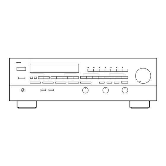
Thank you for selecting this YAMAHA stereo receiver.
OWNER'S MANUAL
CONTENTS
Safety Instructions ................................2
Supplied Accessories ......................... 4
Profile of This Unit .............................. 5
Speaker Setup for This Unit ............... 6
Connections ........................................ 7
Operation .......................................... 10
Operations ........................................ 13
Tuning Operations ............................ 16
Processor (DSP) ............................... 18
Setting the SLEEP Timer .................. 22
Remote Control Transmitter ............. 23
Control Transmitter ........................... 26
Troubleshooting ................................ 27
Specifications ................................... 28
Block Diagram .................................. 29
RX -V670
70W +70W (8Ω) RMS Output Power, 0.03% THD, 20-20,000 Hz (Front)
70W (8Ω) RMS Output Power, 0.08% THD, 1 kHz (Center)
25W + 25W (8Ω) RMS Output Power, 0.3% THD, 1 kHz (Rear)
Automatic Input Balance Control for Dolby Surround
3 Center Channel Modes (NORMAL/WIDE/PHANTOM)
IMPORTANT!
Please record the serial number of this
unit in the space below.
Model:
Serial No.:
The serial number is located on the rear
of the unit.
Retain this Owner's Manual in a safe
place for future reference.
WARNING
TO REDUCE THE RISK OF FIRE OR
ELECTRIC SHOCK, DO NOT EXPOSE
THIS UNIT TO RAIN OR MOISTURE.
Natural Sound Stereo Receiver
40-Station Random Preset Tuning
Video Signal Input/Output Capability
Programmable Remote Control Transmitter
5 Speaker Configuration
SLEEP Timer
CAUTION
RISK OF ELECTRIC SHOCK
DO NOT OPEN
CAUTION: TO REDUCE THE RISK OF
ELECTRIC SHOCK, DO NOT REMOVE
COVER (OR BACK), NO USER-SERVICEABLE
PARTS INSIDE, REFER SERVICING TO
QUALIFIED SERVICE PERSONNEL.
• Explanation of Graphical Symbols
The lightning flash with arrowhead
symbol, within an equilateral triangle,
is intended to alert you to the
presence of uninsulated "dangerous
voltage" within the product's
enclosure that may be of sufficient
magnitude to constitute a risk of
electric shock to persons.
The exclamation point within an
equilateral triangle is intended to alert
you to the presence of important
operating and maintenance
(servicing) instructions in the
literature accompanying the
appliance.
Advertisement
Table of Contents

Related Manuals for Yamaha RX-V670


Summary of Contents for Yamaha RX-V670
-
Page 1: Table Of Contents
Digital Sound Field Processor; 4 Programs for Digital Sound Field Processing and 2 Programs for Dolby Surround (DOLBY PRO LOGIC and ENHANCED) Test Tone Generator for Easier Speaker Output Balance Adjustment Thank you for selecting this YAMAHA stereo receiver. OWNER’S MANUAL CONTENTS Safety Instructions ...2... -
Page 2: Safety Instructions
SAFETY INSTRUCTIONS Read Instructions – All the safety and operating instructions should be read before the unit is operated. Retain Instructions – The safety and operating instructions should be retained for future reference. Heed Warnings – All warnings on the unit and in the operating instructions should be adhered to. - Page 3 This product, when installed as indicated in the instructions contained in this manual, meets FCC requirements. Modifications not expressly approved by Yamaha may void your authority, granted by the FCC, to use the product. 2. IMPORTANT : When connecting this product to accessories and/or another product use only high quality shielded cables.
-
Page 4: Supplied Accessories
SUPPLIED ACCESSORIES After unpacking, check that the following parts are contained. Remote Control Transmitter Batteries (size AA, LR6, UM-3) Indoor FM Antenna AM Loop Antenna User Program Sheets... -
Page 5: Profile Of This Unit
You are the proud owner of this Yamaha stereo receiver –an extremely sophisticated audio component. The Digital Sound Field Processor (DSP) built into this unit takes full advantage of Yamaha’s undisputed leadership in the field of digital audio processing to bring you a whole new world of listening experiences. -
Page 6: Speaker Setup For This Unit
SPEAKER SETUP FOR THIS UNIT SPEAKERS TO BE USED This unit is designed to provide the best sound-field quality with a 5 speaker configuration. The speakers to be used with this unit will be mainly front speakers, rear speakers, and a center speaker. (You can omit the center speaker. Refer to the “4-Speaker Configuration”... -
Page 7: Connections
Before attempting to make any connections to or from this unit, be sure to first switch OFF the power to this unit and to any other components to which connections are being made. CONNECTIONS WITH OTHER COMPONENTS When making connections between this unit and other components, be sure all connections are made correctly, that is to say L (left) to L, R (right) to R, “+”... -
Page 8: Connecting Speakers
OUTLETS is 100 watts (80 watts for Canada model). REMOTE CONTROL (PHONO) connector If you have a YAMAHA turntable with the terminal for remote control, connect it to this connector by using the cable provided with the turntable. This connection allows you to control the turntable from the provided remote control transmitter. -
Page 9: Antenna Connections
ANTENNA CONNECTIONS Each antenna should be connected to the designated terminals correctly, referring to the following figure. Both AM and FM indoor antennas are included with this unit. In general, these antennas will probably provide sufficient signal strength. Nevertheless, a properly installed outdoor antenna will give clearer reception than an indoor one. If you experience poor reception quality, an outdoor antenna may result in improvement. -
Page 10: Adjustment Before Operation
ADJUSTMENT BEFORE OPERATION Speaker balance adjustment This procedure lets you adjust the sound output level balance between the front, center, and rear speakers using the built-in test tone generator. With this adjustment, the sound output level heard at the listening position will be the same from each speaker. This is important for the best performance of the digital sound field processor. - Page 11 For detailed information on the remote control transmitter, refer to “REMOTE CONTROL TRANSMITTER” on page 23. Select the center mode according to your speaker configuration. (Refer to “SPEAKER CONFIGURATION” on page 6.) NORMAL PHANTOM On the feature of each mode, refer to the “Note” shown below.
- Page 12 Adjust the BALANCE control so that the effect sound output level of the left front speaker and the right front speaker are the same. BALANCE Make the sound output level of the center speaker the same as that of the front speakers with the CENTER LEVEL key.
-
Page 13: Operations
PHONES jack To play a source VOLUME ∞ Set to “ ” . — dB Select the desired input source. (For video sources, turn the TV/monitor ON.) * The indicator corresponding to the selected input source will illuminate. Select the front speakers to be used. SPEAKERS * If you use two front speaker systems, press both the A and B switches. - Page 14 To record a source to tape Select the source to be recorded. * To dub from tape to tape, refer to the “Notes” shown below. * When selecting LD/TV, TUNER, CD or PHONO, make sure that the TAPE 1 MON, VCR 1 MON or VCR 2/TAPE 2 MON input selector(s) are not also selected.
-
Page 15: Selecting The Speaker System
Adjusting the BALANCE control Adjust the balance of the output volume to the left and right speakers to compensate for sound imbalance caused by speaker location or listening room conditions. BALANCE Note This control is effective only for the sound from the front speakers. -
Page 16: Tuning Operations
Normally, if station signals are strong and there is no interference, quick automatic-search tuning (AUTOMATIC TUNING) is possible. However, if signals of the station you want to select are weak, you must tune to it manually (MANUAL TUNING). AUTOMATIC TUNING Select the reception band (FM or AM) while watching the display. -
Page 17: Preset Tuning
PRESET TUNING This unit can store station frequencies (selected by tuning operation) by using preset station buttons. With this function, you can select any desired station simply by pressing the corresponding preset station button. Up to 40 stations (8 stations per page) can be programmed. -
Page 18: Using Digital Sound Field Processor (Dsp)
USING DIGITAL SOUND FIELD PROCESSOR (DSP) This unit incorporates a sophisticated, multi-program digital sound field processor, which allows you to expand and shape the audio sound field from both the audio and video sources, for a theater-like experience in the listening/viewing room. This digital sound field processor has 6 programs;... - Page 19 Notes on Operation of Sound Field Programs In the CONCERT VIDEO, MONO MOVIE, ROCK CONCERT and CONCERT HALL modes, no sound is heard from the center speaker. When a monaural sound source is played in the DOLBY PRO LOGIC or ENHANCED mode, no sound is heard from the front speakers and the rear speakers.
-
Page 20: To Play A Source With The Digital Sound Field Processor
To play a source with the digital sound field processor Follow step 1–6 shown in “OPERATIONS” on page Select the desired program that is suitable for the source. PRO LOGIC Adjustment of DELAY TIME You can adjust the time difference between the beginning of the source sound and the beginning of the effect sound with the DELAY TIME control. -
Page 21: Adjustment Of The Center Level
Adjustment of the FRONT EFFECT LEVEL If desired, you can adjust the effect sound output level of the front speakers with this control. The output level is preset to be 80. However, you can adjust the level between 1 and 100. FRONT EFFECT LEVEL Illuminates Adjustment of the CENTER LEVEL... -
Page 22: Setting The Sleep Timer
SETTING THE SLEEP TIMER If you use the SLEEP timer of this unit, you can set this unit to be turned off automatically. When you are going to sleep while enjoying a broadcast or other desired input source, this timer function is helpful. Notes The SLEEP timer can be controlled only with the remote control transmitter. -
Page 23: Remote Control Transmitter
REMOTE CONTROL TRANSMITTER The provided remote control transmitter is designed to control this unit and other YAMAHA components. If the CD player, turntable, LD player and tape deck connected to this unit are YAMAHA components, then this remote control transmitter will also control various functions of each component. - Page 24 For Other Component Control Identify the remote control transmitter keys with your component’s keys. If these keys are identical, their function will be the same. On each key function, refer to the corresponding instruction on your component’s manual. Controls the compact disc player. * DISC SKIP is applicable only to a compact disc changer.
- Page 25 YPC: Set to this position when using preset key functions (for controlling this unit and/or YAMAHA components). * “YPC” is the abbreviation of YAMAHA Preset USER: Set to this position when using “learned” key functions. LEARN: Set to this position when learning new key functions from other remote control transmitters.
-
Page 26: Notes About The Remote Control Transmitter
To Clear a Learned Function Set to “USER”. Press and hold the CLEAR button using the point of a mechanical pencil, etc. CLEAR Press and hold the key where the learned function to be deleted is until the indicator flashes 3 times. To clear two or more functions, repeat step 2 and 3. -
Page 27: Troubleshooting
If the unit fails to operate normally, check the following points to determine whether the fault can be corrected by the simple measures suggested. If it cannot be corrected, or if the fault is not listed in the SYMPTOM column, disconnect the power cord and contact your authorized YAMAHA dealer or service center for help. SYMPTOM The unit fails to turn on when the POWER switch is pressed. -
Page 28: Specifications
SPECIFICATIONS AUDIO SECTION Minimum RMS Output Power per Channel Front L,R 8 ohms, 20 Hz to 20 kHz, 0.03% THD...70W+70W 6 ohms, 20 Hz to 20 kHz, 0.05% THD [U.S.A. and Canada models only] ...80W+80W Center 8 ohms, 1 kHz, 0.08% THD ...70W Rear L,R 8 ohms, 1 kHz, 0.3% THD ...25W+25W Dynamic Power per Channel... -
Page 29: Block Diagram
BLOCK DIAGRAM... - Page 30 YAMAHA ELECTRONIQUE FRANCE S.A. RUE AMBROISE CROIZAT BP70 CROISSY-BEAUBOURG 77312 MARNE-LA-VALLEE CEDEX02, FRANCE YAMAHA ELECTRONICS (UK) LTD. YAMAHA HOUSE, 200 RICKMANSWORTH ROAD WATFORD, HERTS WD1 7JS, ENGLAND YAMAHA SCANDINAVIA A.B. J A WETTERGRENS GATA 1, BOX 30053, 400 43 VÄSTRA FRÖLUNDA, SWEDEN VP86370 BWWR, BB Printed in Japan YAMAHA MUSIC AUSTRALIA PTY, LTD.