
Related Manuals for Siemens MICROMASTER Eco


Summary of Contents for Siemens MICROMASTER Eco
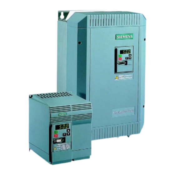
- Page 1 MICROMASTER Eco & MIDIMASTER Eco Operating Instructions Frequency Inverter from 0.75kW to 315kW for Fans and Pumps...
-
Page 2: Table Of Contents
CONTENTS Section 1 Safety and CE Compliance…………………. Section 2 Introduction…………………………………… Section 3 Mechanical Installation……………………… Section 4 Electrical Installation………………………… Section 5 Application Examples……………………….. Section 6 Keypad…………………………………………. Section 7 Display Mode Parameters……………….….. Section 8 Basic Mode Parameters………………….…. 10-11 Section 9 Expert Mode - Important Parameters…...… 12-15 Section 10 Parameter Listing……………………….……. -
Page 3: Safety And Ce Compliance
Loss of life, severe personal injury or property damage can result if the instructions Additional terminals MICROMASTER Eco B+/DC+ and B- contained in this manual are not followed. MIDIMASTER Eco DC+ and DC- Only suitably qualified personnel should work •... - Page 4 EUROPEAN MACHINERY DIRECTIVE The MICROMASTER Eco and MIDIMASTER Eco product range do not fall under the scope of the Machinery Directive. However, the products have been fully evaluated for compliance with the essential Health & Safety requirements of the directive when used in a typical machine application.
-
Page 5: Introduction
INTRODUCTION ............... GENERAL These are the Operating Instructions for the MICROMASTER Eco and MIDIMASTER Eco and are to be used for quick and simple commissioning only. For more details and the complete parameter list for specific applications consult the Eco Reference Manual on our website (details available on back page). -
Page 6: Mechanical Installation
Use an earth braid on 400V ratings 1.5KW and below. CONTROL AND SERIAL COMMUNICATION CABLES Ambient temperature MICROMASTER Eco 0 C to 50 To minimise the effects of radio frequency MIDIMASTER Eco (IP20/21/56) 0 C to 40 emissions and interference:- Ensure that the Eco is not subject to shock, •... -
Page 7: Electrical Installation
Only use the Eco with fan or pump motors (variable torque). Motor Terminals DIRECTION OF ROTATION MICROMASTER Eco - Mains supply, motor and control connections The direction of rotation of the motor can be reversed by changing over two of the output FS7 units connections on the Eco. - Page 8 PE (case) Output Relays (RL1 and RL2) max. 0.8 A/230V AC (Overvoltage cat.2) 5V (max. 250mA) 2.0 A / 30 V DC (resistive rating) Front Panel RS485 D-type RL2B RL2C (NO) (COM) P5V+ MICROMASTER Eco RS485 RANGE (for USS protocol)
-
Page 9: Application Examples
APPLICATION EXAMPLES ..........FAN CONNECTION PUMP CONNECTION L1 L2 L3 L1 L2 L3 0-20mA Pump Typical pump connection To control the speed of the pump in a pumping Typical fan connection system a 0-20 mA control signal is used; this corresponds to a 0-100% motor speed - To speed control a fan between 0-50 Hz, (60 normally 0-50 Hz (60 Hz in North America). -
Page 10: Keypad
KEYPAD ................STOP UP / INCREASE PARAMETER RANGES Display Button Button speed The Eco has three ranges of parameters; Display mode, Basic mode and Expert mode. One of the Basic mode parameters (P199) controls access to the Expert mode parameters. The Basic mode parameters are described in this section. -
Page 11: Display Mode Parameters
DISPLAY MODE PARAMETERS........Parameter Function Range Default Units Operating display (output frequency) Displays the output selected by P001 (an Expert mode parameter). Display selection via P001: 0 = Output frequency (Hz) 4 = Motor torque (% nominal) 1 = Frequency setpoint (i.e. speed at 5 = Motor speed (rpm) which inverter is set to run) (Hz) 6 = USS serial bus status (Code) - Page 12 BASIC MODE PARAMETERS.......... Parameter Function Range Default Units Keypad control 0 or 1 The value of this parameter (0 or 1) configures keypad control. 0 = Control is by digital inputs (P051 to P055 or P356 - refer to Expert mode) 1 = Front panel (keypad) control enabled.
-
Page 13: Expert Mode - Important Parameters
EXPERT MODE - IMPORTANT PARAMETERS ....The Expert Parameters shown below are the more frequently used Expert Parameters. Consult the Eco Reference Manual for the full parameter set. CAUTION • Consult the Reference manual before changing an Expert Parameter Parameter Function Range Description/Notes... - Page 14 EXPERT MODE - IMPORTANT PARAMETERS ....Description/Notes Parameter Function Range (Default) Selection control 0-24 Value Function of P051 Function, Function, function, DIN1 [01] to P055 and low state high state (terminal 5), fixed P356 (0 V) (>10V) frequency 5. Input disabled (P046)** ON right On right...
- Page 15 EXPERT MODE - IMPORTANT PARAMETERS ....Parameter Function Range Description/Notes (Default) Selection relay 0-13 Sets the relay function, output RL1 output RL1 (terminals 18,19 and 20) Selection relay 0-13 Sets the relay function, output RL2 output RL2 (terminals 21 and 22) Value Relay function Active...
- Page 16 EXPERT MODE - IMPORTANT PARAMETERS ....Parameter Function Range Description/Notes (Default) Pulse frequency Sets the pulse frequency (from 2 to 16 kHz) and PWM mode. If silent operation is not absolutely necessary, the losses in the inverter as well as the RFI emissions can be reduced by selecting lower pulse frequencies.
-
Page 17: Parameter Listing
PARAMETER LISTING ............. Parameter Function Range Default Unit *P000 Operating display 0 (output frequency) P001 Display mode *P002 Ramp-up time 0-150.0 *P003 Ramp-down time 0-150.0 P005 Digital frequency setpoint 0-150.0 50.00 (60,00 = North America) *P006 Frequency setpoint source selection *P007 Keypad control 0 or 1... - Page 18 PARAMETER LISTING............. Parameter Function Range Default Unit *P085 Motor rating plate nominal power 0.12-400.0 (hp = North America) P086 Motor current limit 0-200 P087 Motor PTC enable P088 Automatic calibration Ω P089 Stator resistance 0.01-199.99 P091 Serial link slave address 0-30 P092 Serial link baud rate...
-
Page 19: Fault Codes
FAULT CODES ..............Fault Code Cause Corrective Action F001 Overvoltage Check whether supply voltage is within the limits indicated on the rating plate Increase the Ramp-down time (P003) F002 Overcurrent Check whether the motor is obstructed or overloaded Check whether the motor power corresponds to the inverter power Increase the ramp-up time (P002) Check that the cable length limits have not been exceeded Check motor cable and motor for short circuits and earth faults... -
Page 20: Your Parameter Settings
YOUR PARAMETER SETTINGS........Parameter Default Your Parameter Default Your setting setting P000 P089 P001 P091 P002 20.0 P092 P003 20.0 P093 P004 P094 50 (60 North America) P005 50 (60 North America) P095 P006 P101 2 Go to either 0 or 1 after first energised P007 P111... - Page 21 Technical Support Information, Eco Reference Manual and to submit your suggestions for improvements, see our Web Site: http://www.con.siemens.co.uk Address of Congleton Site: SIEMENS plc Automation & Drives Varey Road, Congleton, Cheshire, Great Britain CW12 1PH Technical Support: +49 180 5050222...
- Page 22 Commisioning MICROMASTER Eco Display Parameters Basic Parameters Expert Parameters Select Display via Ramp-up time Automatic restart Parameter 001 Parameter 002 after mains failure. in the Expert 0 -150 sec Parameter 015 Parameter Mode. 0 = display/1 = enable Display frequency.
- Page 23 Herausgegeben vom Bereich Automatisierungs- und Antriebstechnik (A&D) *6SE9586-4AA86* Geschäftsgebiet Standard Drives Postfach 3269, D-91050 Erlangen 6SE9586-4AA86 Siemens plc *H1751-U555-C1* Automation & Drives Standard Drives Division Siemens House G85139-H1751-U555-C1 Varey Road May 1999 Congleton CW12 1PH English Änderungen vorbehalten Order Number : 6SE9586-4AA86...