
Related Manuals for Siemens OXYMAT 64


Summary of Contents for Siemens OXYMAT 64
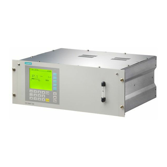
- Page 1 OXYMAT 64 Gas analyzer for measurements of trace oxygen 7MB2041 Operating Instructions June 2008 • Continuous gas analysis...
- Page 3 General information Description Installing and connecting Continuous gas analysis Commissioning Gas analyzer for measurement of trace oxygen Operation OXYMAT 64 Repair, maintenance and servicing Operating Instructions Technical data Dimension drawings and charts Spare parts and accessories Appendix List of abbreviations/acronyms...
- Page 4 Trademarks All names identified by ® are registered trademarks of the Siemens AG. The remaining trademarks in this publication may be trademarks whose use by third parties for their own purposes could violate the rights of the owner.
-
Page 5: Table Of Contents
Mains connection .........................28 3.4.3 Connection of the signal lines ......................28 3.4.4 Motherboard pin assignments......................30 3.4.5 Plug connector assignment of the optional board and PROFIBUS ..........31 3.4.6 Example of Autocal connection....................32 Dimensions for preparing installation...................33 OXYMAT 64 Operating Instructions, 06/2008, A5E00880383-03... - Page 6 Drift values (function 25) ......................64 5.4.3.8 Sensor calibration (function 26) ....................64 5.4.4 Measuring ranges ........................67 5.4.4.1 Measuring ranges submenu ....................... 67 5.4.4.2 Select measuring ranges (function 40) ..................67 5.4.4.3 Define measuring ranges (function 41)..................70 OXYMAT 64 Operating Instructions, 06/2008, A5E00880383-03...
- Page 7 Cleaning the device ........................108 Removing faults .........................109 6.6.1 Alarms and messages .......................109 6.6.2 Maintenance requests........................110 6.6.3 Fault messages..........................111 6.6.4 Other faults..........................112 Technical data ............................113 Dimension drawings and charts......................117 Dimension drawings........................117 Gas flow chart ..........................119 OXYMAT 64 Operating Instructions, 06/2008, A5E00880383-03...
- Page 8 9.4.5 Decontamination declaration..................... 127 Appendix..............................129 Declaration of conformity ......................129 Overview of operating functions....................131 ESD guidelines.......................... 132 List of abbreviations/acronyms ......................135 List of abbreviations ........................135 Glossary ..............................139 Index..............................147 OXYMAT 64 Operating Instructions, 06/2008, A5E00880383-03...
-
Page 9: General Information
For further information, or in the case of problems which are not covered in enough detail in this document, please request the required information from your local or responsible Siemens regional office. Note In particular, before using the device for new research and development applications, we recommend that you first contact us to discuss the application in question. -
Page 10: Special Information And Warnings
All obligations on the part of Siemens AG are contained in the respective sales contract, which also contains the complete and solely applicable liability provisions. The provisions defined in the sales contract for the responsibility for defects are neither extended nor limited by the remarks in this document. -
Page 11: Description
Gases with flammable components at concentrations above the lower explosive limit must not be supplied to the analyzer. The OXYMAT 64 gas analyzer is used to measure traces of oxygen in pure gases. Fields of application ● Manufacture of technical gases:... -
Page 12: Design
● 5-digit measured value display (decimal point counts as digit) ● Washable membrane keyboard with five softkeys ● Menu-prompted operation for parameterization, configuration, test functions, calibration ● Graphical display of the concentration curve; time intervals can be parameterized OXYMAT 64 Operating Instructions, 06/2008, A5E00880383-03... - Page 13 1 2 3 4 CLEAR INFO MEAS ENTER OXYMAT 64 Figure 2-1 Membrane keyboard and graphic display Status line for display of analyzer state (configurable) Two code levels according to NAMUR (maintenance and specialist levels) Display of activated measuring ranges...
- Page 14 ● RS 485/RS 232 converter ● RS 485/Ethernet converter ● RS 485/USB converter ● Linked in networks via PROFIBUS-DP/PA interface ● SIPROM GA software as servicing and maintenance tool (SIPROM GA Version 1.9.14 and higher) OXYMAT 64 Operating Instructions, 06/2008, A5E00880383-03...
-
Page 15: Principle Of Operation
The catalytically inactive sensor has the same basic design as the CAZ auf. However, the contacts and the electrode surface inside the cylinder are made of a specially developed material which largely prevents catalytic oxidation of H , CO and CH OXYMAT 64 Operating Instructions, 06/2008, A5E00880383-03... - Page 16 Measuring electrode Reference electrode Heating Thermocouple Contact to reference electrode Contact to measuring electrode Ceramic protective layer Tube made of ZrO and Y or CaO mixed oxide ceramic Sample gas input Figure 2-2 Sensor design OXYMAT 64 Operating Instructions, 06/2008, A5E00880383-03...
-
Page 17: Influence Of Interfering Gas
/ 357 vpm CH -1.1 vpm O 25 vpm O / 70 vpm H -3 vpm O 5 vpm O / 9.6 vpm H -0.55 vpm O 170 vpm O / 930 vpm C -118 vpm O OXYMAT 64 Operating Instructions, 06/2008, A5E00880383-03... -
Page 18: Materials Used In The Sample Gas Path
FIDAMAT 6 as well as ULTRAMAT 23 offer the following communication possibilities: ● ELAN interface ● SIPROM GA (Version 1.9.14 and higher) ● PROFIBUS DP/PA ● Generic communications interface (only ULTRAMAT 6E, OXYMAT/ULTRAMAT 6E, OXYMAT 61, OXYMAT 6). OXYMAT 64 Operating Instructions, 06/2008, A5E00880383-03... -
Page 19: Elan Interface
232 cables RS 485 bus connector with bridge Analyzer RS 485 cable RS 485 bus connector RS 485 network 9-pin SUB-D connector Optional: RS-485 repeater Figure 2-3 Typical structure of an ELAN network (RS 232) OXYMAT 64 Operating Instructions, 06/2008, A5E00880383-03... - Page 20 SIMATIC cable / bus line 6XV1 830-OEH10 SIMATIC bus connector 6ES7 972-OBB11-OXAO 9-pin SUB-D connector 6ES7 972-OBB11-OXAO Repeater 6ES7 972-OAA01-OXAO Further information can be found in the ELAN interface description: Order Nos.: ● C79000-B5200-C176 German ● C79000-B5274-C176 English OXYMAT 64 Operating Instructions, 06/2008, A5E00880383-03...
-
Page 21: Siprom Ga Functions
● Windows NT 4.0 ● Windows 2000 ● Windows XP Ordering information Order No. SIPROM GA software, German/English selectable during S79610-B4014-A1 installation, consists of 1 CD with installation instructions, software, product certificate and registration form OXYMAT 64 Operating Instructions, 06/2008, A5E00880383-03... -
Page 22: Profibus Dp/Pa
2.6.4 PROFIBUS DP/PA PROFIBUS DP/PA is the leading fieldbus on the market. All Siemens gas analyzers with an optional – also retrofittable – plug-in card are Profibus-compatible and comply with the binding "Device profile for analyzers" defined by the PNO (PROFIBUS International). Central access to the system analyzers is possible with the SIMATIC PDM software tool. - Page 23 Description 2.6 Communication Figure 2-4 Typical structure of a PROFIBUS system OXYMAT 64 Operating Instructions, 06/2008, A5E00880383-03...
-
Page 25: Installing And Connecting
5 °C to 45 °C is observed. Do not install an OXYMAT 6 or 61 in the direct vicinity of the OXYMAT 64. Due to their functional principle, the OXYMAT 6 and OXYMAT 61 emit magnetic stray fields. Distances of up to 50 cm are therefore necessary between the devices. -
Page 26: Gas Connections And Internal Gas Routing
If the sample gas is to flow into an exhaust line, use as short a line as possible or a transition to a larger diameter to make sure that no flow resistance is produced in the exhaust line. OXYMAT 64 Operating Instructions, 06/2008, A5E00880383-03... -
Page 27: Sample Gas Quality
3.3.3 Pressure sensors The OXYMAT 64 has an internal pressure sensor for correcting the influence of pressure on the measured value. The pressure sensor is present on the sensor electronics, and measures the sample gas pressure via the sample gas outlet pipe. The pressure sensor need not be considered further in the device installation. - Page 28 - With internal pressure regulator: 3000 to 6000 hPa Sample gas outlet; sample gas must flow off free of dynamic pressure Pressure regulator (ordered version) sensor Pressure sensor Bypass restrictor Pressure switch Flow metering tube Purging gas connection 10 Restrictor 11 Restrictor OXYMAT 64 Operating Instructions, 06/2008, A5E00880383-03...
- Page 29 This is particularly important with long sample gas lines between the gas sampling point and the analyzer. Please make absolutely sure that the flow in the OXYMAT 64 does not exceed 125 ml/min. Figure 3-2 Gas path for low-pressure version Sample gas inlet;...
-
Page 30: Electric Connection
● As a measure to suppress sparking across the relay contacts (e.g. limit relays), RC elements must be connected as shown in the following figure. Note that the RC element results in a drop-out delay for an inductive component (e.g. solenoid valve). OXYMAT 64 Operating Instructions, 06/2008, A5E00880383-03... - Page 31 The core cross-section must be ≥ 0.5 mm². We recommend cables of type JE-LiYCY...BD. The cable length of the analog output depends on the load. OXYMAT 64 Operating Instructions, 06/2008, A5E00880383-03...
-
Page 32: Motherboard Pin Assignments
Installing and connecting 3.4 Electric connection 3.4.4 Motherboard pin assignments Figure 3-4 OXYMAT 64, 19" rack unit, motherboard pin assignments OXYMAT 64 Operating Instructions, 06/2008, A5E00880383-03... -
Page 33: Plug Connector Assignment Of The Optional Board And Profibus
Installing and connecting 3.4 Electric connection 3.4.5 Plug connector assignment of the optional board and PROFIBUS Figure 3-5 OXYMAT 64, 19" rack unit, pin assignments on the optional board and PROFIBUS plug connector OXYMAT 64 Operating Instructions, 06/2008, A5E00880383-03... -
Page 34: Example Of Autocal Connection
Installing and connecting 3.4 Electric connection 3.4.6 Example of Autocal connection Figure 3-6 Connections and valve plan "Autocal" OXYMAT 64 Operating Instructions, 06/2008, A5E00880383-03... -
Page 35: Dimensions For Preparing Installation
Installing and connecting 3.5 Dimensions for preparing installation Dimensions for preparing installation OXYMAT 64 Figure 3-7 Dimensions for preparing installation (front view and plan view) OXYMAT 64 Operating Instructions, 06/2008, A5E00880383-03... - Page 36 Installing and connecting 3.5 Dimensions for preparing installation Figure 3-8 Dimensions for preparing installation (view from left and rear view) OXYMAT 64 Operating Instructions, 06/2008, A5E00880383-03...
-
Page 37: Commissioning
It is essential to observe the following statements and information! 4.1.2 Explosion hazard DANGER Explosion hazard The OXYMAT 64 gas analyzer must not be used to measure mixtures which are ignitable in normal operation. WARNING Explosion hazard The analyzer must not be operated in potentially explosive atmospheres. -
Page 38: Electrical Safety
4.1.5 Danger of burns CAUTION Danger of burns Temperatures of up to 300 °C can occur in the analyzer when switched on. The plant owner is finally responsible for switching-on. OXYMAT 64 Operating Instructions, 06/2008, A5E00880383-03... -
Page 39: Commissioning Preparations
Correction of cross-interference is only meaningful if the effect of the interfering gas is lower than the expected O concentration. For examples of interfering gas offsets, refer to the chapter "Influence of interfering gas". See also Sample gas quality (Page 25) Influence of interfering gas (Page 15) OXYMAT 64 Operating Instructions, 06/2008, A5E00880383-03... -
Page 40: Adjusting The Sample Gas Flow
'WARMUP' is displayed in the bottom line. Achievement of the full measuring accuracy of the device depends on the ambient temperature. At room temperature, this is approx. 3 hours following switching on. OXYMAT 64 Operating Instructions, 06/2008, A5E00880383-03... -
Page 41: Leak Test
"Technical zero". An appropriate calibration gas must be selected as the "Zero gas" for this purpose. Its O concentration should always be < 30% of the smallest span to be adjusted. Enter the zero setpoint using function 22. OXYMAT 64 Operating Instructions, 06/2008, A5E00880383-03... -
Page 42: General Information On Calibration
If you have selected single calibration (total calibration deactivated), repeat the calibration procedure for each measuring range individually with the corresponding calibration gases. (In function 22, a calibration gas must be entered for every measuring range!) OXYMAT 64 Operating Instructions, 06/2008, A5E00880383-03... -
Page 43: Calibration Examples
Enter setpoints for zero 5.8 vpm Zero setpoint and span 43.3 vpm Span setpoint Calibrate zero Calibrate using calibration gas for zero point (zero gas) Calibrate span Calibrate using calibration gas for span OXYMAT 64 Operating Instructions, 06/2008, A5E00880383-03... - Page 44 Calibrate using calibration gas for zero point (zero gas) Calibrate span Calibrate using calibration gas for span Note The operation and input options of the named functions are described in detail in the chapter "Operation". OXYMAT 64 Operating Instructions, 06/2008, A5E00880383-03...
-
Page 45: Operation
CODE O.OOO 1 2 3 4 CLEAR INFO MEAS ENTER OXYMAT 64 Figure 5-1 Measured value display and control panel 1 Status display Display of activated measuring ranges with the current range marked 2 Display of dimension Limit marker on bargraph... -
Page 46: Button Meanings
■ = activated (ON state; also in status message in the status line) □ = deactivated (OFF state; also in status message in the status line) ► = access a submenu/subfunction ● = trigger a function/subfunction (e.g. Start calibration...) OXYMAT 64 Operating Instructions, 06/2008, A5E00880383-03... -
Page 47: Device Operating Modes
Settings and inputs can be • made operation level. Functional check active • In this mode, you can parameterize/calibrate the Measured value can be • device. influenced OXYMAT 64 Operating Instructions, 06/2008, A5E00880383-03... - Page 48 Operation 5.1 General information about operation Schematic diagram of the operating sequence with operating modes Figure 5-2 Operating sequence O64 with operating modes OXYMAT 64 Operating Instructions, 06/2008, A5E00880383-03...
-
Page 49: Measured Value Display
It must not be confused with the "Measure" operating state (also "Measuring state") of the device! CTRL CODE O.650 1 1 2 2 3 3 4 4 20,O Figure 5-3 Measured value display OXYMAT 64 Operating Instructions, 06/2008, A5E00880383-03... -
Page 50: Menu Control
(►). A softkey is assigned to this component. Press this softkey to call the main menu. 5.3.2 Entering a submenu The main menu consists of five submenus. Main menu Analyzer status Calibration Measuring ranges Parameters Configuration Figure 5-5 Main menu OXYMAT 64 Operating Instructions, 06/2008, A5E00880383-03... - Page 51 Decoding also activates the measured value memory, providing you have parameterized it using function 77. The coding status of the device can be read in the status line of the measured value display as a symbol "■ CODE" for "coded" or "□ CODE" for "decoded". OXYMAT 64 Operating Instructions, 06/2008, A5E00880383-03...
-
Page 52: Jump Back To Coded/Decoded Display Mode
2. Press the softkey of the component with the arrow ►. If the desired function is protected by a code, you will be asked to enter the code. See also Overview of operating functions (Page 51) OXYMAT 64 Operating Instructions, 06/2008, A5E00880383-03... -
Page 53: Operating Functions
Save analog output (measured value) Calibration tolerance Change codes Analyzer test Select language Pressure correction Correction of cross-interference Switch valves Linear temperature compensation Faults on/off PROFIBUS configuration Change dimension Factory settings Overview of operating functions OXYMAT 64 Operating Instructions, 06/2008, A5E00880383-03... -
Page 54: Analyzer Status
Indication of date of manufacture and device serial number ● Object version: Indication of the hardware design of the device ● Software version/date: Version of the motherboard software; date, version of boot software of motherboard OXYMAT 64 Operating Instructions, 06/2008, A5E00880383-03... -
Page 55: Diagnostic Values (Function 2)
Logbook settings (function 60) (Page 80) Error on/off (function 87) (Page 99) 5.4.2.5 Display measuring ranges (function 4) The measuring ranges defined using function 41 are listed here. However, you cannot carry out any changes in this function. OXYMAT 64 Operating Instructions, 06/2008, A5E00880383-03... -
Page 56: Calibration
"...continue" to access further functions. This menu is protected by the code of code level 1. The OXYMAT 64 offers the option of a manual or automatic calibration (Autocal: function 24). The latter is only possible with an optional board which contains an additional eight binary outputs and eight relay outputs. -
Page 57: Zero Calibration (Function 20)
Electric time constants (function 50) (Page 71) 5.4.3.3 Span calibration (function 21) Single calibration ("Measure" operating state required) 21 Sp.cal. all MRs Calibration MR 1 Calibration MR 2 Calibration MR 3 Calibration MR 4 Figure 5-10 Carry out single calibration OXYMAT 64 Operating Instructions, 06/2008, A5E00880383-03... - Page 58 When the actual value has stabilized, you can initiate the calibration process by pressing the fourth softkey. The actual value is now made to agree with the setpoint. If a calibration is carried out incorrectly (e.g. using the wrong calibration gas) repeat the complete calibration procedure. OXYMAT 64 Operating Instructions, 06/2008, A5E00880383-03...
-
Page 59: Setting The Setpoints (Function 22)
With this function, select between the total and single calibration of the measuring ranges. Total calibration means that you adjust one "leading measuring range" and all other measuring ranges are calibrated using the switching ratio. If this function is not activated, each measuring range is calibrated separately. OXYMAT 64 Operating Instructions, 06/2008, A5E00880383-03... -
Page 60: Autocal (Function 24)
Autocal Check (automatic check that the set calibration tolerances are complied with, without calibration). The settings for "Autocal Check" (4th subfunction) only refer to the check of the calibration tolerances without calibration. AUTOCAL/Check operating mode Autocal/-check mode Figure 5-15 AUTOCAL/Check operating mode OXYMAT 64 Operating Instructions, 06/2008, A5E00880383-03... - Page 61 Canceling has no influence on the time cycle. All valid calibration processes are retained. AUTOCAL sequence Acal/-check sequence Figure 5-16 AUTOCAL/Check sequence With this subfunction, you can combine several calibration phases to form one Autocal sequence. OXYMAT 64 Operating Instructions, 06/2008, A5E00880383-03...
- Page 62 4. Sample gas intermediate operation: 30 minutes 5. Calibration with calibration gas 3, after 1.4 minutes of flushing The specified Autocal sequence is shown in the following function screens. Acal/-check sequence Figure 5-17 Example of Autocal sequence OXYMAT 64 Operating Instructions, 06/2008, A5E00880383-03...
- Page 63 List for the Autocal sequence: Autocal sequence Zero gas 1 Zero gas 2 (air with function 26) Calibration gas 1 Calibration gas 2 Calibration gas 3 Calibration gas 4 Flush sample gas Sample gas intermediate operation Signaling contact OXYMAT 64 Operating Instructions, 06/2008, A5E00880383-03...
- Page 64 > 1. Note As long as Autocal is activated (Autocal ■), access to functions 20 and 21 is blocked. If you activate these functions anyway, a corresponding message appears on the display. OXYMAT 64 Operating Instructions, 06/2008, A5E00880383-03...
- Page 65 – Via binary input – Via cycle "Autocal/Check 2. The device executes the sequence as parameterized in the subfunction sequence" See also Relay outputs (function 71) (Page 82) Binary inputs (function 72) (Page 84) OXYMAT 64 Operating Instructions, 06/2008, A5E00880383-03...
-
Page 66: Drift Values (Function 25)
O The calibration takes place in two steps. 1. The sensor zero is first adjusted using ambient air. 2. The span of the sensor signal is then calibrated using a previously defined calibration gas. OXYMAT 64 Operating Instructions, 06/2008, A5E00880383-03... - Page 67 – With low-pressure devices you must guarantee that the flow is 7.5 l/h. Note Connection to a compressed air system When connecting to a compressed air system, ensure that the air is free of oil and grease. Measurements will otherwise be permanently falsified. OXYMAT 64 Operating Instructions, 06/2008, A5E00880383-03...
- Page 68 If the message 'Calibration successful' is displayed, the calibration has been completed. If an error occurs during the calibration, you can use function 75 (save/load data / load user data) to reload the old calibration data. OXYMAT 64 Operating Instructions, 06/2008, A5E00880383-03...
-
Page 69: Measuring Ranges
● At least two measuring ranges must be available. One measuring range is said to be present when the following is true: Measuring range start-of-scale value ≠ full-scale value ● The spans must become greater or smaller ● The measuring ranges must "border on" each other or overlap OXYMAT 64 Operating Instructions, 06/2008, A5E00880383-03... - Page 70 Start of measuring range End of measuring range Lower switchover point: select the smaller measuring range Upper switchover point: select the larger measuring range Figure 5-28 Measuring range type A OXYMAT 64 Operating Instructions, 06/2008, A5E00880383-03...
- Page 71 Lower switchover point: select the smaller measuring range Upper switchover point: select the larger measuring range Figure 5-30 Measuring range type B The following applies to measuring range switching: Figure 5-31 Measuring range switch, type B OXYMAT 64 Operating Instructions, 06/2008, A5E00880383-03...
-
Page 72: Define Measuring Ranges (Function 41)
If the start-of-scale and full-scale values are "0", the measuring range is deactivated. 5.4.5 Parameters 5.4.5.1 Parameters submenu Parameters 5O El. time constants 51 Limits 52 On/off configuration 53 Status messages ...continue Figure 5-33 Parameters submenu OXYMAT 64 Operating Instructions, 06/2008, A5E00880383-03... -
Page 73: Electric Time Constants (Function 50)
"ti" and "ta". By cleverly combining these three parameters, you can achieve a low display delay (90% time) despite high noise suppression. The effect on the set attenuation parameters can be observed in the bottom line. The "live" measured value is displayed here. OXYMAT 64 Operating Instructions, 06/2008, A5E00880383-03... -
Page 74: Limits (Function 51)
"Limit…" You can change to the next limit using the fifth softkey ( See also Logbook (function 3) (Page 53) On/off functions (function 52) (Page 73) Relay outputs (function 71) (Page 82) OXYMAT 64 Operating Instructions, 06/2008, A5E00880383-03... -
Page 75: On/Off Functions (Function 52)
Besides the functions listed in the table "Functions switched on/off by function 52", function 52 can also be used to address other service functions. These are restricted to service engineers and are only visible when the service code is entered (code level 3). OXYMAT 64 Operating Instructions, 06/2008, A5E00880383-03... -
Page 76: Status Messages (Function 53)
If you parameterized the analog output with "Memory on" using function 77, this remains in the fault current until you leave the corresponding code level, and therefore "Operator control mode", and return to "Coded display mode" (press [MEAS] twice). OXYMAT 64 Operating Instructions, 06/2008, A5E00880383-03... -
Page 77: Graphical Representation Of Measured Values (Function 54)
Limits (function 51) (Page 72) Analog output memory (function 77) (Page 91) 5.4.5.6 Graphical representation of measured values (function 54) 54 G. signal displ. Period 1O min Period 24 h Figure 5-38 Graphical representation of measured values OXYMAT 64 Operating Instructions, 06/2008, A5E00880383-03... - Page 78 Range 4 Figure 5-40 Parameters for measured value representation "Optimum measured value display" Activate in order to have the measured value axis automatically scaled. The device adapts the scale to the measured value dispersion. OXYMAT 64 Operating Instructions, 06/2008, A5E00880383-03...
-
Page 79: Measured Value Display (Function 55)
With the fourth softkey , you can carry out an LCD test. Various test screens are then displayed in succession. From "Coded/decoded display mode", you can reestablish the basic setting by entering [8][8][8][8] [ENTER]. OXYMAT 64 Operating Instructions, 06/2008, A5E00880383-03... -
Page 80: Date/Time (Function 58)
Press the third softkey in order to accept the set data. These then appear at the bottom edge of the display. See also Logbook (function 3) (Page 53) Logbook settings (function 60) (Page 80) OXYMAT 64 Operating Instructions, 06/2008, A5E00880383-03... -
Page 81: Measuring Point Switching (Function 59)
You can allocate a signal relay to each measuring point relay. This allows measuring point identification separate from the measuring point relay. Configure the signal relay, also using function 71. See also Relay outputs (function 71) (Page 82) OXYMAT 64 Operating Instructions, 06/2008, A5E00880383-03... -
Page 82: Logbook Settings (Function 60)
From the "Coded/decoded display mode", you can also delete logbook entries with the button sequence [5][5][5][5] [ENTER]. Status messages such as maintenance requests or faults cannot be suppressed by "blocking". This only prevents an entry into the logbook. See also Logbook (function 3) (Page 53) OXYMAT 64 Operating Instructions, 06/2008, A5E00880383-03... -
Page 83: Configuring
(see also table "Configurations of the analog output") are possible: ● 0 – 20 mA ● 2 – 20 mA ● 4 – 20 mA ● NAMUR/4 – 20 mA (with limit at 3.8 mA). OXYMAT 64 Operating Instructions, 06/2008, A5E00880383-03... -
Page 84: Relay Outputs (Function 71)
With this function, you can assign each relay functions listed in the table "Relay outputs", whereby you may only assign each function once. In other words, for example, "Fault" may not be assigned to two relays at the same time. OXYMAT 64 Operating Instructions, 06/2008, A5E00880383-03... - Page 85 Autocal difference too large (function 24) Dimension % v/v For identification purposes * This function is only available if the analyzer is fitted with an optional Autocal board See also Motherboard pin assignments (Page 30) OXYMAT 64 Operating Instructions, 06/2008, A5E00880383-03...
-
Page 86: Binary Inputs (Function 72)
72 Binary inputs Vacant Vacant Vacant Vacant ...cont. Figure 5-50 Define binary inputs Assign one of the activation functions listed below to each input as you like, whereby every function may only be assigned once. OXYMAT 64 Operating Instructions, 06/2008, A5E00880383-03... - Page 87 N, X Note: Effective activation only possible in "Measure" operating state! Relay must be configured for zero gas. After activation, the device changes from "Measure" to "Calibration" operating state. See also "Example - binary inputs" OXYMAT 64 Operating Instructions, 06/2008, A5E00880383-03...
- Page 88 The device can no longer be decoded. • The device can no longer be set to "Remote". • The message "Measuring protection activated" appears in the status line of the measured value display. OXYMAT 64 Operating Instructions, 06/2008, A5E00880383-03...
-
Page 89: Elan Configuration (Function 73)
ELAN telegram. In order to avoid unnecessarily loading the device and the ELAN network, however, the function should only be switched on as needed! Further ELAN details can be found in the ELAN interface description: ● (C79000-B5200-C176 German) ● (C79000-B5276-C176 English). OXYMAT 64 Operating Instructions, 06/2008, A5E00880383-03... -
Page 90: Reset (Function 74)
Press softkey 3 to re-establish the factory settings. A confirmation query is set up in this function. In order to actually load the respective data in the memory, you must confirm with "yes". If you select "no", this is cancelled. OXYMAT 64 Operating Instructions, 06/2008, A5E00880383-03... - Page 91 If you neglect to do this, there is a danger that a previous (unwanted) configuration will be loaded by "Load user data" (function 75). The following figure contains an overview of the interaction between the various memory modules. Figure 5-54 Interaction between the memory modules OXYMAT 64 Operating Instructions, 06/2008, A5E00880383-03...
-
Page 92: Suppression Of Short-Term Noise Signals (Function 76)
If a change in concentration directly follows a fault, this may be displayed after a delay. When this function is activated, the settings of function 50 ("Electric time constants") must be taken into account, since these are executed first. See also Electric time constants (function 50) (Page 71) OXYMAT 64 Operating Instructions, 06/2008, A5E00880383-03... -
Page 93: Analog Output Memory (Function 77)
% of current MR: Signal tolerance violation. Figure 5-57 Setting the calibration tolerances With this function, you define the calibration tolerances. "Signal tolerance violation" With softkey 3 , you activate or deactivate the tolerance monitoring. OXYMAT 64 Operating Instructions, 06/2008, A5E00880383-03... - Page 94 If the zero / span deviates by more than the parameterized value compared to the last calibration, and if "Signal tolerance violation" is activated, the corresponding relay signalizes a maintenance request. See also Total / single calibration (function 23) (Page 57) OXYMAT 64 Operating Instructions, 06/2008, A5E00880383-03...
-
Page 95: Change Codes (Function 79)
After pressing the [INFO] key, a message is displayed in plain text. The [MEAS] and [ESC] keys retain their "jump back" function. OXYMAT 64 Operating Instructions, 06/2008, A5E00880383-03... - Page 96 The current state of the binary inputs is displayed in the "Binary" column. Analog test With the analog test, the analog output is set to a constant current of 0 to 24000 µA for testing purposes. The analog input displays the input currents in µA. OXYMAT 64 Operating Instructions, 06/2008, A5E00880383-03...
-
Page 97: Language Selection (Function 81)
(see also Table "Examples of typical interfering gas offsets on a catalytically inactive sensor"). Note A differentiation must always be made with the correction of cross-interference as to whether the interfering gas has a constant or variable concentration. OXYMAT 64 Operating Instructions, 06/2008, A5E00880383-03... - Page 98 Correction of cross-interference with constant influence of interfering gas With softkey 2, you can set whether the correction of cross-interference should only apply to certain measuring ranges. "Interference" Under , enter the value of the zero offset. OXYMAT 64 Operating Instructions, 06/2008, A5E00880383-03...
- Page 99 With softkey 2, you can set whether this correction of cross-interference should only apply to certain measuring ranges. OXYMAT 64 Operating Instructions, 06/2008, A5E00880383-03...
-
Page 100: Switch Valves (Function 85)
The "Switch valves" function only applies to the relay functions "Zero gas", "Calibration gas 1 to 4" and "Sample gas". Only one valve can be switched at a time, since the valves are mutually interlocked. See also Relay outputs (function 71) (Page 82) OXYMAT 64 Operating Instructions, 06/2008, A5E00880383-03... -
Page 101: Error On/Off (Function 87)
With this function, you can set the PROFIBUS station address. The address can be set from 0 to 126. Under TAG you can display the tag assigned to a device in the ELAN network (or the 16 characters thereof). OXYMAT 64 Operating Instructions, 06/2008, A5E00880383-03... -
Page 102: Changing The Dimension (Function 91)
Changing the dimension With function 91 you can choose vpm range, automatic switchover, or % range. A relay function can be selected to signal the currently used display, and is active with % v/v. OXYMAT 64 Operating Instructions, 06/2008, A5E00880383-03... - Page 103 10 seconds. This guarantees that the measured value is only enabled again when all limit relays have been correctly set again. Since these are parameterized independent of one another, they can briefly output incorrect values if the functional check is not activated. OXYMAT 64 Operating Instructions, 06/2008, A5E00880383-03...
-
Page 104: Factory Settings (Function 99)
With this function, the operator can access the factory functions level. These settings are intended only for maintenance personnel and are therefore protected by an additional code. After activating this function, a message appears which prompts you to enter the corresponding code. OXYMAT 64 Operating Instructions, 06/2008, A5E00880383-03... -
Page 105: Repair, Maintenance And Servicing
If standards or directives apply to the gases/components used, these must also be observed. To allow maintenance work, the top cover can be removed and the front panel swung forwards. If maintenance work is interrupted for more than two hours, the analyzer must be closed again. OXYMAT 64 Operating Instructions, 06/2008, A5E00880383-03... -
Page 106: Sensor Module
5. Remove the ribbon cable from the motherboard. 6. Remove the RS232 communication cable from the sensor electronics. 7. Remove the metal bracket. 8. To install, carry out the above steps in reverse order. OXYMAT 64 Operating Instructions, 06/2008, A5E00880383-03... - Page 107 Calibration Following replacement or readjustment of the sensor module, the analyzer must be recalibrated according to Section "Calibration". See also Leak test (Page 39) General information on calibration (Page 40) Calibration examples (Page 41) OXYMAT 64 Operating Instructions, 06/2008, A5E00880383-03...
-
Page 108: Installation/Retrofitting Of Pressure Regulator
In addition, do not overtighten the union nut, otherwise the gasket (PTFE) will be permanently deformed and lose its sealing function. See also Leak test (Page 39) OXYMAT 64 Operating Instructions, 06/2008, A5E00880383-03... -
Page 109: Replacement Of Motherboard And Optional Board
The appropriate fuse ratings can be taken from the spare parts list. Table 6- 1 Fuse ratings in Ampere Voltage Fuse rating: 200 to 240 V 0.63 T/250 100 to 120 V 1 T/250 OXYMAT 64 Operating Instructions, 06/2008, A5E00880383-03... -
Page 110: Cleaning The Device
In the case of devices used in hazardous areas, the control panel (keyboard and window) must only be cleaned with a damp cloth. Cleaning the interior After opening the device, you can blow out the interior carefully with a compressed air gun, if necessary. OXYMAT 64 Operating Instructions, 06/2008, A5E00880383-03... -
Page 111: Removing Faults
You can block the logbook or even delete the messages in it with function 60. This might be especially helpful during test operation. All messages can be shut off individually with function 87. In normal operation, we recommend that this option is not used. OXYMAT 64 Operating Instructions, 06/2008, A5E00880383-03... -
Page 112: Maintenance Requests
5 °C to 45 °C. External maintenance External signal Check (function 72 must be request configured accordingly) Autocal check deviation Violation of the tolerance was determined during an "Autocal check" OXYMAT 64 Operating Instructions, 06/2008, A5E00880383-03... -
Page 113: Fault Messages
Eliminate the cause of the fault message input Fault if the analyzer is in Autocal mode Sample gas flow too low Pressure in sample gas supply line Provide sufficient pressure too low (> 2000 hPa) OXYMAT 64 Operating Instructions, 06/2008, A5E00880383-03... -
Page 114: Other Faults
100 hPa (rel.). Occurrence of sporadic spikes See also function 76; inform service department if necessary Green LED on the rear of the analyzer flashes in a certain Inform Service sequence (not regular flashing) OXYMAT 64 Operating Instructions, 06/2008, A5E00880383-03... -
Page 115: Technical Data
132 V), 48 to 63 Hz or 200 to 240 V AC (rated range of use 180 V to 264 V), 48 to 63 Hz Power consumption (analyzer) Approx. 37 VA Fuse ratings 100 ... 120 V 1T/250 200 ... 240 V 0.63T/250 OXYMAT 64 Operating Instructions, 06/2008, A5E00880383-03... - Page 116 Approx. 10 to 30 s, depending on version purged at 125 ml/min) Time for signal processing in the device < 1 s Table 7- 5 Technical data – pressure correction range Pressure correction range Pressure sensor 800 to 1100 hPa (abs.) OXYMAT 64 Operating Instructions, 06/2008, A5E00880383-03...
- Page 117 Sample gas flow < 2% of smallest possible span according to rating plate with 10 ml/min change in flow within the permissible flow range OXYMAT 64 Operating Instructions, 06/2008, A5E00880383-03...
- Page 118 Referred to sample gas pressure 1000 hPa (abs.), sample gas flow 125 ml/min and ambient temperature 25 °C Dew point must not be fallen below! The error of the calibration gas must be considered in addition * Based on DIN EN 61207 / IEC 1207 OXYMAT 64 Operating Instructions, 06/2008, A5E00880383-03...
-
Page 119: Dimension Drawings And Charts
Dimension drawings and charts Dimension drawings OXYMAT 64 Figure 8-1 Dimensions for preparing installation (front view and plan view) OXYMAT 64 Operating Instructions, 06/2008, A5E00880383-03... - Page 120 Dimension drawings and charts 8.1 Dimension drawings Figure 8-2 Dimensions for preparing installation (view from left and rear view) OXYMAT 64 Operating Instructions, 06/2008, A5E00880383-03...
-
Page 121: Gas Flow Chart
Pressure regulator (ordered version) sensor Pressure sensor Bypass restrictor Pressure switch Flow metering tube Purging gas connection 10 Restrictor 11 Restrictor The OXYMAT 64 must only be purged with air, otherwise the measured value will be falsified. OXYMAT 64 Operating Instructions, 06/2008, A5E00880383-03... - Page 122 Gas path for low-pressure version Sample gas inlet; flow 125 ml/min (7.5 l/h) Sample gas outlet; sample gas flows off free of dynamic pressure sensor Flow metering tube Pressure switch Pressure sensor Outlet restrictor OXYMAT 64 Operating Instructions, 06/2008, A5E00880383-03...
-
Page 123: Spare Parts And Accessories
The spare parts list corresponds to the technical status of April 2007. SIEMENS Figure 9-1 Example of type nameplate for OXYMAT 64 Ordering example The order for spare parts must contain: Table 9- 1... -
Page 124: Sensor Module
Flow metering tube A5E01061561 Incl. brackets Sensor module / with A5E01058837 Complete with sensor and catalytically active cell sensor electronics; pre- calibrated With catalytically inactive cell A5E01058838 Pressure switch as spare A5E01007406 part OXYMAT 64 Operating Instructions, 06/2008, A5E00880383-03... -
Page 125: Electronics
W79054-L1010-T630 200 V - 240 V, 0.63 A G-type fuse T1L250 W79054-L1011-T100 100 V - 120 V, 1 A Optional board C79451-A3480-D511 Relay A5E00057307 PROFIBUS PA A5E00057312 PROFIBUS DP A5E00057164 Firmware update for Profibus OXYMAT 64 Operating Instructions, 06/2008, A5E00880383-03... -
Page 126: Service
General information If servicing is necessary, you can obtain the required information such as contact person and address from your responsible partner or from the following Internet address. See also Contacts (http://www.siemens.com/processinstrumentation/contacts) Partner (http://www.automation.siemens.com/partner) OXYMAT 64 Operating Instructions, 06/2008, A5E00880383-03... -
Page 127: Repairs
The return delivery address applicable to you can be obtained from the following address. See also Services & Support (http://www.siemens.com/automation/service&support) 9.4.3 Spare parts Your regional contact partner will be pleased to receive your order. In addition, there is a central phone number for every country at which you can contact us. -
Page 128: Error Description
It is confirmed that the returned part has not come into contact with highly toxic or radioactive gases or substances, or been exposed to radioactive or high-energy radiation. Company, department, name, first name Location: Date: Signature: Software update ( ) yes ( ) no OXYMAT 64 Operating Instructions, 06/2008, A5E00880383-03... -
Page 129: Decontamination Declaration
Confirmation It is herewith confirmed that all residues of the medium have been removed. The device is therefore free of all dangerous and toxic materials. Company, department, name, first name Location: Date: Signature: OXYMAT 64 Operating Instructions, 06/2008, A5E00880383-03... -
Page 131: Appendix
Richtlinie des Rates zur Angleichung der Rechtsvorschriften der Mitgliedstaaten betreffend elektrische Betriebsmittel zur Verwendung innerhalb bestimmter Spannungsgrenzen. (geändert durch 93/68/EWG). Annex A is integral part of this declaration. Anhang A ist integraler Bestandteil dieser Erklärung. OXYMAT 64 Operating Instructions, 06/2008, A5E00880383-03... - Page 132 Die Konformität mit den auf Blatt 1 angeführten Richtlinien wird nachgewiesen durch die Einhaltung folgender Normen (variantenabhängig): Directive Standard / Reference number Edition Richtline Norm / Referenznummer Ausgabedatum 2004/108/EC EN 61326/A3 App. A 2003 73/23/EEC EN 61010-1 (2 ed.) 2001 OXYMAT 64 Operating Instructions, 06/2008, A5E00880383-03...
-
Page 133: Overview Of Operating Functions
Save analog output (measured value) Calibration tolerance Change codes Analyzer test Select language Pressure correction Correction of cross-interference Switch valves Linear temperature compensation Faults on/off PROFIBUS configuration Change dimension Factory settings Overview of operating functions OXYMAT 64 Operating Instructions, 06/2008, A5E00880383-03... -
Page 134: Esd Guidelines
The electrostatic discharge current may lead to latent failure of a module, that is, this damage may not be significant immediately, but in operation may cause malfunction. OXYMAT 64 Operating Instructions, 06/2008, A5E00880383-03... - Page 135 In this way, the discharged energy can not affect the sensitive devices. Discharge your body before you start taking any measurements on a module. Do so by touching grounded metallic parts. Always use grounded measuring instruments. OXYMAT 64 Operating Instructions, 06/2008, A5E00880383-03...
-
Page 137: List Of Abbreviations/Acronyms
EPROM Erasable programmable read-only memory Electromagnetic compatibility Fluorocaoutchouc, a plastic (ASTM name), commercial name e.g. Viton Fluorocaoutchouc, a plastic (DIN/ISO name), commercial name e.g. Viton Gas analysis Ground Possibly Possibly Hydrogen Hydrogen sulfide Hydrocarbon OXYMAT 64 Operating Instructions, 06/2008, A5E00880383-03... - Page 138 MΩ Megaohms n. B. As required NAMUR Standards working committee for measuring and control technology in the chemical industry Neon, an inert gas Ammonia Number Oxygen o. Ä. Or similar Process automation Personal computer OXYMAT 64 Operating Instructions, 06/2008, A5E00880383-03...
- Page 139 Universal Serial Bus; serial bus system for connecting external devices to a computer Volts Video Graphics Array, a graphics card standard Yttric oxide Volume parts per million e.g. For example Zirconium dioxide Δ Difference (delta) Ω Ohms OXYMAT 64 Operating Instructions, 06/2008, A5E00880383-03...
-
Page 141: Glossary
Glossary Adapter board Board contained in the standard configuration of the OXYMAT 64. It is used to preprocess sensor signals and the measured signal. Additional electronics Generic term for all optional boards. Back wall of housing Part for sealing the rear housing opening of the device. - Page 142 The factory setting is the value of a parameter when an analyzer is delivered from the factory. Front panel Front part of a device, usually with clear identification features (e.g. device name, manufacturer logo, etc.). Function Numbered software function of a device. Functions are listed in submenus. OXYMAT 64 Operating Instructions, 06/2008, A5E00880383-03...
- Page 143 Leak-tightness Reliability of piping system against escaping of gases. Limit alarm Signaling of upward/downward violation of a limit. Limit monitoring Function which monitors the observation of adjustable limits, and signals if these are violated. OXYMAT 64 Operating Instructions, 06/2008, A5E00880383-03...
- Page 144 Automatic switching over of measuring ranges. Also referred to as "autorange" in the software. Membrane keyboard Keyboard whose keys are protected jet-proof against atmospheric influences by a membrane (IP 65 according to EN 60529). OXYMAT 64 Operating Instructions, 06/2008, A5E00880383-03...
- Page 145 A gas which has been extracted from a process and is to be analyzed. Signaling contact Usually a floating contact contained in electronic components (e.g. relay) which signals the occurrence of an event to a control unit. OXYMAT 64 Operating Instructions, 06/2008, A5E00880383-03...
- Page 146 Restarting the device from its "warm" state with the last set parameters. Warm-up phase Time which the analyzer needs to reach operating temperature. It counts as one of the operating states. Zero calibration Calibration of the zero point with a suitable zero gas. OXYMAT 64 Operating Instructions, 06/2008, A5E00880383-03...
- Page 147 Zirconium dioxide (ZrO2) as the sensor material is a high-performance ceramic belonging to the group of oxide ceramics, and is therefore a non-metallic, inorganic material. It is non- magnetic, extremely resistant to acids and alkalis, and exhibits a high resistance to chemical, thermal and mechanical influences. OXYMAT 64 Operating Instructions, 06/2008, A5E00880383-03...
-
Page 149: Index
Index ESD guidelines, 123 Guidelines ESD guidelines, 123 OXYMAT 64 Operating Instructions, 06/2008, A5E00880383-03... - Page 152 Siemens AG Subject to change without prior notice A5E00880383 Industry Automation (IA) A5E00880383-03 Sensors and Communication © Siemens AG 2008 Process Analytics 76181 KARLSRUHE A5E00880383 GERMANY www.siemens.com/processanalytics 4 019169 158404...