
Related Manuals for Siemens SIMATIC TI555


Summary of Contents for Siemens SIMATIC TI555
- Page 1 SIMATIC TI545/TI555 System Manual Order Number: PPX:545/555–8101–2 Manual Assembly Number: 2586546–0084 Second Edition...
- Page 2 All Rights Reserved — Printed in USA Reproduction, transmission or use of this document or contents is not permitted without express consent of Siemens Industrial Automation, Inc. All rights, including rights created by patent grant or registration of a utility model or design, are reserved.
- Page 3 MANUAL PUBLICATION HISTORY SIMATIC TI545/TI555 System Manual Order Manual Number: PPX:545/555–8101-2 Refer to this history in all correspondence and/or discussion about this manual. Event Date Description Original Issue 02/93 Original Issue (2801030-0001) Second Edition 10/94 Second Edition (2801030-0002)
- Page 4 LIST OF EFFECTIVE PAGES Pages Description Pages Description Cover/Copyright Second History/Effective Pages Second iii — xii Second 1-1 — 1-8 Second 2-1 — 2-15 Second 3-1 — 3-21 Second 4-1 — 4-20 Second 5-1 — 5-10 Second 6-1 — 6-5 Second 7-1 —...
-
Page 5: Table Of Contents
Contents Preface Chapter 1 System Overview Features ............... . Hardware Description . - Page 6 Power System Grounding ............2-13 Earth Ground .
- Page 7 Chapter 4 Cabling and Wiring the System Connecting Input Power ............Guidelines .
- Page 8 Chapter 6 Starting Up the TI545/TI555 System Powering Up the TI545/TI555 System ..........Overview .
- Page 9 Appendix A System Specifications Series 505 System Specifications ..........Appendix B Module Power Consumption Series 505 Modules .
- Page 10 List of Figures Figure 1-1 Typical TI555-1102 Control System ..........Figure 1-2 TI545/TI555 System Using Series 500 and Series 505 Components .
- Page 11 Figure 4-13 XON/XOFF Printer Handshaking ..........4-20 Figure 4-14 READY/BUSY Printer Handshaking .
- Page 12 List of Tables Table 1-1 TI545/TI555 Capacity/Performance ......... . . Table 1-2 Program Storage Using EEPROM and EPROM .
-
Page 13: Preface
SIMATIC TI545/TI555 Programmable Logic Controller (PLC) system. NOTE: This manual describes the SIMATIC TI545-1102 CPU, and both the SIMATIC TI555-1101 and -1102 CPUs. Information in this manual does not apply to the SIMATIC TI545-1101 CPU. For the information concerning the SIMATIC TI545-1101 CPU refer to SIMATIC TI545 System Manual: PPX:545-8101-x. - Page 14 (IEC-65A/WG6) for programmable controllers (released as IEC 1131–2, Programmable Controllers Part 2: Equipment Requirements and Tests, First Edition, 1992–09). Contact Siemens Industrial Automation, Inc., for information about regulatory agency approvals that have been obtained on the TI545/555 systems and Series 505 units.
- Page 15 Chapter 1 System Overview Chapter 1 System Overview Features ............... . Hardware Description .
-
Page 16: Chapter 1 System Overview
Features The TI545/TI555 CPUs and support equipment comprise a computer-controlled system that is capable of controlling complex manufacturing systems. This system performs the same functions as relays, static control, or card logic control systems. It can detect the change in state of input signals from such devices as pushbuttons, limit switches, and analog sensors. - Page 17 Interrupt I/O allows for fast reaction to external events. Support for Redundant Remote Base Controller. Immediate I/O Updates allow your application program to access an I/O point multiple times during a controller scan. Cyclic RLL allows you to create an additional RLL program that runs independently of the main RLL program.
-
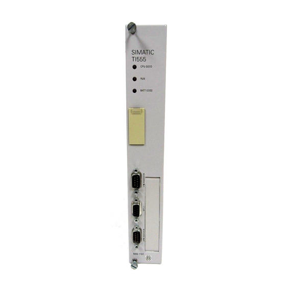
Page 18: Figure 1-1 Typical Ti555-1102 Control System
Features (continued) Siemens SIMATIC SIMATIC TI555 TI505 CPU GOOD BATT GOOD 555–1102 Figure 1-1 Typical TI555–1102 Control System TI545/TI555 systems (see Figure 1-1) are designed for use in applications that require discrete and analog control. Components include the CPU and the support devices that provide operator communication, I/O control, and power (see Figure 1-2). - Page 19 The TI545/TI555 controller system uses individual Series 505 or Series 500 I/O modules for I/O interfaces. A full line of discrete, analog, word, and intelligent I/O modules are available for handling almost any input or output specification. These I/O modules are rugged, plug-in devices capable of functioning in harsh environments within the operating specifications.
-
Page 20: Hardware Description
Hardware Description Series 505 Base The CPUs are housed in a Series 505 base assembly. A base assembly has Assemblies slots for the CPU or remote base controller (RBC), a power supply, and the I/O modules. Three base assembly models are currently available. Each has the following number of slots for I/O modules. -
Page 21: Communication Ports
Communication The CPU has two communications ports; features and descriptions are Ports listed below. Both ports are configured as Data Terminal Equipment (DTE). Port 1 — RS-232 (9-pin male) is used to either program the CPU by an IBM PC/AT compatible computer with APT or TISOFT, or to attach equipment such as the Timer/Counter Access Module (TCAM), a CVU100, or other operator interface using RS-232. -
Page 22: Real-Time Clock
Hardware Description (continued) Real-time Clock The CPU contains a real-time clock which includes the following information: Year (two digits), Month, Day of month, and Day of week. Hour, minute, second, tenths and hundredths of a second. Programming You can use APT to program the CPU. APT is a graphic programming Software environment that eliminates the need for you to work in relay ladder logic when you create your application program. -
Page 23: Chapter 2 Pre-Installation Guidelines Planning Your Installation
Chapter 2 Pre-installation Guidelines Chapter 2 Pre-installation Guidelines Planning Your Installation ............Defining Control . -
Page 24: Calculating Power Needs
Planning Your Installation Preparing the site for installation of your TI545/TI555 controller consists of the following tasks. Defining control requirements Determining the number of controllers needed Determining the panel and grounding layout NOTE: Since no two applications are identical, use these recommendations as general guidelines only. -
Page 25: Safety Considerations
Safety Considerations Pre-installation planning and site preparation must include consideration of hazards to personnel in the event of a system failure. The equipment connected to the control system must include interlocks and safety switches to help prevent operation during a system failure. Although the specific steps depend on the application, the general precautions include the following data. -
Page 26: Operator Safety Switches
Safety Considerations (continued) Operator Safety Provide a means for disconnecting power — independent of the controller — Switches from the output loads when a machine is not operating, or when it is necessary for the operator to reach into the machine. Power must be removed by a non-semiconductor switch or a physically-wired relay contact, placed to interrupt power to the output. -
Page 27: Jog Or Inch Switch
JOG or INCH Bypass the programmable control system with an external JOG or INCH Switch switch during machine loading or setup operations. See Figure 2-3. Switch or contact closed in the jog or inch mode User-supplied critical loads which could Switch or contact cause injury open in the JOG... -
Page 28: Enclosure And Temperature Considerations
Enclosure and Temperature Considerations Enclosure Selection An enclosure should provide the following features: Easy access to components. A common ground potential on the cabinet. A secure vertical panel or rails. Conformance to electrical standards. An electromagnetic shield. Access restricted to authorized personnel only. Cooling and heat dissipation. -
Page 29: Guidelines For Fuses/Circuit Breakers
Guidelines for Fuses/Circuit Breakers Fusing the Use the following guidelines for installing fuses/circuit breakers; see Controller and Figure 2-4. The sizes and types of fuses/circuit breakers depend on the Remote I/O Base specified power distribution requirement. A circuit breaker before isolation transformer (isolation transformers may not be required if your power distribution system does not have a high level of noise). -
Page 30: Definition And Source Of Electrical Noise
Definition and Source of Electrical Noise Electrical Noise Electrical noise is defined as any unwanted electrical signal which enters the control equipment. Noise signals cover the entire spectrum of frequencies and may have any wave shape. A major difficulty with noise problems is that they can occur at random intervals. -
Page 31: Correcting Noise Problems
Correcting Noise Problems When potential noise problem sources are identified, two general methods are available to handle them. These methods are described in the following sections. Noise snubbing. Noise isolation. These methods are described in the following sections. Noise Snubbing Noise snubbing reduces noise at its source. -
Page 32: Figure 2-6 Contact Noise Snubbing
Correcting Noise Problems (continued) You can also use contact snubbing (shown in Figure 2-6) as an alternative type of snubbing. Both types of snubbing cause the physical devices to come on or go off more slowly. The resistance-capacitance (RC) and metal oxide varistor (MOV) elements should have minimal effect on system timing;... -
Page 33: Noise Isolation
Noise Isolation The second approach to handling noise problems is to isolate the problem device and its wiring from the electronics and associated signal wiring. You may accomplish this by increasing the physical distance from some types of noisy devices. For extreme cases, electrostatic (metal) shielding may be required. -
Page 34: Wiring Considerations
Wiring Considerations Guidelines Consider the following guidelines before installing any system or power wiring. Always use the shortest possible single length cable. Avoid placing system and field wiring in the vicinity of high-energy and/or high frequency wiring. Keep field input wiring, output wiring, and all other types of wiring in the panel physically separated when possible. -
Page 35: Power System Grounding
Power System Grounding Earth Ground In some installations, a metal conduit that connects to the neutral phase at the circuit-breaker box supplies the earth ground of the power receptacle. Depending on site conditions, this metal conduit may conduct current from other sources that can interfere with the operation of the equipment. -
Page 36: Grounding The Controller
Power System Grounding (continued) Grounding the When installing the controller, ensure that noise is minimized by following Controller these guidelines. Use the ground connection (Figure 2-9) to attach one end of a ground wire; attach the other end to a nearby grounding rod that meets all electrical specifications required for an earth ground. -
Page 37: Figure 2-10 Example Of Ground Connection
CAUTION A good grounding system is essential for proper operation of the system. It is one of the most important considerations in planning your installation. Failure to provide a good grounding system could result in death or serious injury to personnel and/or damage to equipment. Ensure that you have a good grounding system when you install your equipment. - Page 38 Chapter 3 Installing Series 505 System Hardware Overview of Installation Procedures ..........Series 505 Bases .
-
Page 39: Chapter 3 Installing Series 505 System Hardware
Overview of Installation Procedures The following chart identifies the tasks for installing Series 505 system hardware. Install Base Rack mounting (Section 3.3) Panel mounting (Section 3.4) Install Power Supply (Section 3.5) Install TI545/TI555 Controller (Section 3.6) Install Remote Base Controller (Section 3.7) Install I/O Modules (Section 3.8) Installing Series 505 System Hardware TI545/TI555 System Manual... -
Page 40: Series 505 Bases
Series 505 Bases Description The controller is housed in a Series 505 base assembly. A base assembly has slots for the programmable controller or remote base controller (RBC), power supply, and the I/O modules. Four base assembly models are currently available (see Table 3-1). Table 3-1 Base Assembly Models Model Number of Slots... -
Page 41: Rack Mounting Series 505 Base
Rack Mounting Series 505 Base PPX:505–6516, Use the following steps, and Figure 3-1, for mounting the base in a standard 16-Slot Base 19-inch rack. Align two bracket holes with two screw holes located on the sides of base. Secure each bracket to base with two screws installed through the bracket holes. -
Page 42: Panel Mounting Series 505 Bases
Panel Mounting Series 505 Bases Series 505 Bases Use the following steps for panel mounting in an NEMA enclosure. PPX:505–6516, PPX:505–6508, Open NEMA enclosure door. PPX:505–6504 Drill four holes in sub-panel of NEMA enclosure with a #21 drill bit. Refer to Figure 3-2 through Figure 3-4 for screw-hole dimensions for each base. -
Page 43: Figure 3-3 Screw-Hole Dimensions For Ppx:505-6504 Bases
Panel Mounting Series 505 Bases (continued) 0.64 8.10 0.64 (16.26) (205.74) (16.26) 10.47 (265.94) 8.97 (227.81) 1.47 (37.31) 8.69 (220.79) Note: in. PPX:505–6504 (mm) Figure 3-3 Screw-hole Dimensions for PPX:505–6504 Bases Installing Series 505 System Hardware TI545/TI555 System Manual... -
Page 44: Figure 3-4 Screw-Hole Dimensions For Ppx:505-6508 Bases
11.29 0.64 0.64 (286.77) (16.26) (16.26) 10.47 (265.94) 8.97 (227.81) 1.47 (37.31) 11.93 (303.2) PPX:505–6508 Note: in. (mm) Figure 3-4 Screw-hole Dimensions for PPX:505–6508 Bases Installing Series 505 System Hardware TI545/TI555 System Manual... -
Page 45: Figure 3-5 Mounting Brackets To Base
Panel Mounting Series 505 Bases (continued) Tap the drilled holes with a #10-32 tap. Align two bracket holes with two screw holes located on each side of base. See Figure 3-5. Secure each bracket to base with two screws installed through the bracket holes. -
Page 46: Installing Series 505 Power Supply
Installing Series 505 Power Supply Power Budget for The total power consumption of all I/O modules (including the Series 505 Base programmable controller and RBC) drawing power from a Series 505 power supply must not exceed 55.0 W from the +5 VDC output and 3.75 W from the –5 VDC output. -
Page 47: Figure 3-8 Selecting Input Voltage-Ppx:505-6660 Only
Installing Series 505 Power Supply (continued) CAUTION Attempting to operate the PPX:505–6660 power supply at 220 VAC with 110 VAC selected, or 110 VAC with 220 VAC selected, results in damage to power supply. Attempting to operate the PPX:505–6663 power supply outside the designed voltage range of 20 to 30 VDC may cause damage to the power supply. -
Page 48: Installing The Ti545/Ti555 Cpu
Installing the TI545/TI555 CPU CPU/RBC Location The CPU/RBC must always be installed in the second slot from the left in a Base (beside the power supply module), as shown in Figure 3-9. Figure 3-9 Location of CPU/RBC in a Series 505 Base CAUTION Electronic equipment can be damaged by electrostatic discharge. -
Page 49: Installing And Removing The Cpu
Installing the TI545/TI555 CPU (continued) Installing and Refer to Figure 3-10 and follow the steps below to install the CPU. Removing the CPU Disconnect power to the base. WARNING Disable all power before installing or removing the CPU. Failure to do so could cause death or serious injury and/or damage to equipment. -
Page 50: Cpu Battery
CPU Battery A permanent, rechargeable battery protects user memory and programs during a power cycle. Battery backup typically lasts six months at temperatures ranging from 0 to 60 C provided the battery was fully charged. If the battery LED does not light, the battery may be discharged. A blinking LED indicates a marginal charge. -
Page 51: Using Port 1
Installing the TI545/TI555 CPU (continued) Using Port 1 Switch 2 selects Port 1 as, either a programming port, or a printer port; see Figure 3-12 for port locations. This port uses a RS-232/RS-423 signaling protocol and uses a RS-232 pinout arrangement with a RS-423 (+5 V) signal level extending up to 50 feet. -
Page 52: Setting Baud Rates
Setting Baud Rates Switches 3 through 8 are used to set baud rates for Ports 1 and 2. Switches 3, 4, and 5 set Port 1 baud rates (Table 3-2). Switches 6, 7, and 8 set Port 2 baud rates (Table 3-3). Table 3-2 Port 1 Baud Rate Settings Dipswitches Baud Rate... -
Page 53: Installing Series 505 Remote Base Controller
Installing Series 505 Remote Base Controller RBC Placement in The RBC must always be installed in the second slot from the left (adjacent Bases to the power supply module) in a remote base. Dipswitches There are two dipswitches, SW 2 and SW 3, located on the components side of the RBC. -
Page 54: Series 505 Rbc Sw 3 (Factory) Dipswitch Settings
Series 505 RBC The factory dipswitch, labeled SW 3 on the board is for factory use only. Do SW 3 (Factory) not change the settings on this dipswitch. If the dipswitch setting is Dipswitch Settings accidentally changed, or you are installing a new RBC, refer to Table 3-5 for the proper dipswitch settings. -
Page 55: Figure 3-14 Series 505 Rbc Jumper Locations
Installing Series 505 Remote Base Controller (continued) The RBC has a jumper to select the output state during a communication loss (Figure 3-14). If the output modules in the remote base have a selection switch, the freeze selection will override the output module’s selection. Outputs off (default) OFF FRZ... -
Page 56: Installing And Removing Series 505 Rbc
Installing and Use the following steps to install and remove a Series 505 RBC. Removing Series 505 RBC CAUTION The RBC can be damaged by electrostatic discharge. Ensure that personnel make contact with a grounded conductive pad and/or wear a grounded wrist strap when handling the RBC. Disconnect power to the base. -
Page 57: Series 505 Rbc Led Display
Installing Series 505 Remote Base Controller (continued) WARNING Control devices can fail in an unsafe condition that could result in death or serious injury and/or damage to equipment. Do not change the base thumbwheel numbers when the system is operating. This may cause the base to be logged off the system. When the base is logged off the system, all discrete outputs will be turned off, analog outputs will be frozen, and word and discrete inputs will go to 0. -
Page 58: Installing Series 505 I/O Modules
Installing Series 505 I/O Modules Mixing I/O A mix of I/O modules can be used with one base; you can combine input, Modules output, word input, word output, and intelligent modules in a single base. Installing and Use the following steps for installing and removing Series 505 I/O modules Removing in the base. - Page 59 Chapter 4 Cabling and Wiring the System Connecting Input Power ............Guidelines .
-
Page 60: Chapter 4 Cabling And Wiring The System
Connecting Input Power Guidelines To connect the Series 505 power supply, and the Series 500 remote I/O base to the external power source, follow these guidelines. Use 14 AWG solid or stranded wire. If you use stranded wire, the wire should be twisted and trimmed. -
Page 61: Figure 4-1 Supplying Power With The Ppx:505-6660A
Tighten screws. Refer to Chapter 2 for grounding guidelines. Siemens SIMATIC TI505 DC POWER GOOD AC LINE AC NEUTRAL GROUND Figure 4-1 Supplying Power with the PPX:505–6660A Cabling and Wiring the System TI545/TI555 System Manual... -
Page 62: Cable Routing
Cable Routing Guidelines Follow these suggestions when planning your cable routing. Allow for system growth. Provide for attachment of future I/O bases by routing cable through all possible areas of plant expansion. The TI545/TI555 can have a trunk line (attached to its I/O) that extends up to 3300 feet (1000 m) using RS-485 (twisted pair) cables. -
Page 63: Under-Floor Routing
Under-Floor In under-floor routing, the cable can be enclosed in ducts or, with raised Routing flooring, in the open air. Duct systems are better protected against unauthorized taps or terminal blocks, but expansion is more difficult and expensive than with open air systems. Open air systems provide more freedom of access, and allow maximum system expansion and flexibility. -
Page 64: Installing Remote I/O Cables
Installing Remote I/O Cables Cabling Options Effective with Firmware Release 3.0 the TI545/TI555 provides two cabling options for the remote I/O system: Non-redundant I/O cabling using twisted pair (RS-485) media. Redundant I/O cabling using coaxial (RF) media. This manual describes the twisted pair media. If you are installing a Redundant I/O system follow the instructions in the SIMATIC TI505 Redundant I/O Systems User Manual, PPX:505–8125–2. -
Page 65: User-Supplied Equipment
User-Supplied User-supplied components are listed below: Equipment RS-485 cables. Taps (terminal blocks). 9-Pin D-connectors (male) and shell. Terminal lugs. Mounting the Installation procedures for mounting the terminal block depend upon the Terminal Block cable installation technique used. Refer to mounting instructions provided by the terminal block vendor for additional information. -
Page 66: Preparing Cables (For Drop Lines)
Installing Remote I/O Cables (continued) Preparing Cables Use the following procedures to prepare drop line cables to connect the (for Drop Lines) programmable controller and RBC to terminal blocks: Strip back 1.50 inches (3.8 cm) of the sleeving on one end of the cable. There are three wires when the sleeving is stripped back;... -
Page 67: Connecting A Cpu Drop Line
Strip back 1.50 in. (3.8 cm) of the sleeving on the other end of the cable. Remove 0.13 in. (0.33 cm) of each color-coded insulation to expose the bare wires. Install each wire end onto a terminal lug according to directions provided by the vendor. -
Page 68: Figure 4-5 Adding A Terminating Resistor
Installing Remote I/O Cables (continued) If you are not using another terminal block, install a terminating resistor across the terminal screws securing the cable wires with the colored coded insulation jacket. See Figure 4-5. NOTE: The terminating resistor value depends on the type of cable being used. -
Page 69: Connecting The Rbc Drop Line
Connecting the Use the following procedure to connect a cable between the RBC and RBC Drop Line terminal block. Prepare another cable as described on page 4-8. Place the cable D-connector onto the RBC RS-485 connector. Tighten two cable connector screws to secure the cable D-connector to the RBC RS-485 connector. -
Page 70: Connecting Terminal Block Trunk Lines
Installing Remote I/O Cables (continued) Connecting The cable that connects the terminal blocks is called a trunk line. See Terminal Figure 4-2. The maximum trunk length depends on the cable type and Block Trunk Lines number of terminal blocks used in your installation. See Table 4-2. Table 4-2 Maximum Cable Length for Trunk Lines Maximum Distance in Feet (Meters) Number of... -
Page 71: Alternate Cables
Alternate Cables Three commercially available cables provide an acceptable level of I/O communication in an industrial environment when used in accordance with Table 4-2. Belden cable 9860 is a large conductor cable that provides a low attenuation and distortion for long trunk lines. Belden cable 9271 is a smaller and more flexible cable suitable for short trunk lines and all drop line cables. -
Page 72: Configuration Requirements
Installing Remote I/O Cables (continued) Configuration Follow these guidelines when installing RS-485 trunk line cabling. Requirements Measure the maximum length (listed in Table 4-2) from the CPU to the most distant tap. See Figure 4-7. *Terminating *Terminating Resistor Maximum Trunk Length Resistor T = Terminal Block *A terminating resistor must be installed on the end terminal blocks. -
Page 73: Figure 4-9 Multiple Tap Connections In Close Proximity
Where several connections need to be made close together, it is better to place a single terminal block in the trunk line and connect all nearby equipment to that terminal block (Figure 4-9). Make multiple connections like this..or this... Remote Base Remote... -
Page 74: Preparing Trunk Line Cables
Installing Remote I/O Cables (continued) The ideal cable installation is a single, unbranched trunk line with short drop cables and a termination resistor at each end of the trunk. NOTE: For installations with five connections or less that have a cable length between the controller and the most distant RBC less than 30m (100 feet), any cable configuration can be used. -
Page 75: Connecting Trunk Line To Terminal Blocks
Connecting Trunk Use the following procedures to connect two terminal blocks. See Line to Terminal Figure 4-11. Blocks Loosen three terminal screws on terminal block A and install second set of cable terminal lugs onto the terminal block. NOTE: Ensure that the wires of the second set of terminal lugs match with those of the first set of terminal lugs. -
Page 76: Connecting Modems
Connecting Modems Overview The CPU can communicate through Port 1 to an operator interface via dedicated line or dial-up phone modems. Dedicated line operation is a line used exclusively to connect the modems. Dial-up phone operation connects the modems by telephone lines. Refer to Figure 4-12 for a typical configuration. -
Page 77: Dedicated Line Operation
Dedicated Line Use these procedures to establish communication between modems in a Operation dedicated line configuration. Connect the modem configuration. Ensure that the CPU controller and modem baud rates are set to the same value. NOTE: If the modems are auto-bauding, ensure that the controller baud rate is set within the baud rate range of the modems. -
Page 78: Connecting A Printer
Connecting a Printer Overview The CPU has the capability to send information to a printer through the use of an SF program or SF subroutine. The printer connects to Port 1 and uses RS-232 protocol. Cabling for the two available handshaking options are as follows: XON/XOFF printer handshaking;... - Page 79 Chapter 5 Using an EEPROM or EPROM Introduction ..............Program Storage .
-
Page 80: Chapter 5 Using An Eeprom Or Eprom
Introduction Program Storage The CPU offers the option of storing your application program in non-volatile form. Using Electrically Erasable Programmable Read-Only Memory (EEPROM), or Erasable Programmable Read-Only Memory (EPROM [UV-EPROM]), is discussed in the following sections. See Table 5-1 for a description of available EEPROMs and EPROMs. Table 5-1 Program Storage Using EEPROM and EPROM Storage Type Size... -
Page 81: Using An Eprom
The EEPROM stores the user program including the following: Relay ladder logic (RLL). K memory. U memory. S memory (PID loops, analog alarms, and SF programs). Memory configuration. I/O configuration. Password , if installed. Scan configuration. After storage in the EEPROM, this data is saved even if power is cycled without a backup battery. -
Page 82: Eeprom Functions
Introduction (continued) EEPROM Functions After your EPROM has been programmed, it is portable and can be used in any other TI545–1102 or TI555 CPU of compatible or newer software revision. EPROMS are available from your distributor for EPROM applications. You can manage operation of EEPROMs by using AUX Function 84 on your programming unit. -
Page 83: Ti545/Ti555 Memory And Mode Status At Power-Up
TI545/TI555 Memory and Mode Status at Power-up When you power up a TI545/TI555 system, the CPU checks the status of the EEPROM (EPROM) and the battery. A clear (un-programmed) EEPROM (EPROM) is equivalent to having no EEPROM (EPROM) installed. Table 5-3 lists mode and memory status (after power up) that result from various battery and EEPROM (EPROM) conditions. -
Page 84: Installing Eeproms And Eproms
Installing EEPROMs and EPROMs Follow instructions in this section to install an EEPROM or EPROM in your CPU. NOTE: If you are installing an EEPROM and intend to download a program (from RAM memory), ensure that the good back-up battery is fully charged and enabled. - Page 85 Note location of notches Figure 5-1 EEPROM (EPROM) Socket and Jumper Pins Using an EEPROM or EPROM TI545/TI555 System Manual...
-
Page 86: Copying A Program Into An Eeprom
Copying a Program into an EEPROM To copy a program into your EEPROM, you must first enter the program into the CPU. Verify that your program is correct, save your program to your programming unit hard disk, and then continue with the steps listed below. - Page 87 If the program is correct and you want to run the program from EEPROM, use the Source Toggle option to select EEPROM as the program source. WARNING Electronic devices can operate in an unsafe condition that can cause death or serious injury and/or damage to equipment. When you select EEPROM, the controller is cleared and then loaded with the EEPROM content.
-
Page 88: Editing A Program Stored In Eeprom
Editing a Program Stored in EEPROM You can edit the program and data stored in an EEPROM by following the steps listed below. NOTE: If necessary, refer to your SIMATIC TI505 Programming Reference manual for detailed instructions about executing AUX Functions. Using your programming unit and the AUX Function 84 option, select EEPROM as the program source. - Page 89 Chapter 6 Starting Up the TI545/TI555 System Powering Up the TI545/TI555 System ..........Overview .
-
Page 90: Powering Up The Ti545/Ti555 System
Powering Up the TI545/TI555 System Overview This section provides general guidelines for powering up your TI545/TI555 system system. WARNING You must be fully informed about safety procedures before you power up the TI545/TI555 system. Not knowing so could result in death or serious injury and/or damage to equipment. - Page 91 Check AC input power for proper voltages. Ensure that the jumper in the back of the power supply is set for the correct voltage. Ensure that all I/O interface cables are properly connected to I/O interface connectors. Ensure that all configured bases are properly connected, there are no crimps or breaks in the cable, and base addresses are correct.
-
Page 92: Ti545 Cpu Memory Configuration
TI545 CPU Memory Configuration Memory The TI545 CPU memory is user configurable. The actual ranges of memory Configuration types depend upon how the memory has been configured. Ranges for memory types are listed in Table 6-1. You can increase the memory allocated to a particular memory type, a block at a time, up to the maximum listed in Table 6-1. -
Page 93: Ti555 Cpu Memory Configuration
TI555 CPU Memory Configuration Memory The TI555 CPU memory is user configurable. The actual ranges of memory Configuration types for each model of the CPU depend upon how the memory has been configured. Ranges for memory types are listed in Table 6-2. You can increase the memory allocated to a particular memory type, a block at a time, up to the maximum listed in Table 6-2. - Page 94 Chapter 7 Troubleshooting Troubleshooting by Using Auxiliary Functions ........Overview .
-
Page 95: Troubleshooting By Using Auxiliary Functions
Troubleshooting by Using Auxiliary Functions Overview The TI545/TI555 CPU has self-checking and diagnostic capabilities that can be used for troubleshooting purposes. The diagnostics and self-checks are accessible through the Auxiliary Function menu on your programming device. When you display the Auxiliary Function menu, the following functions are available for resetting the CPU, initiating diagnostics or displaying diagnostic information: Power-up restart —... -
Page 96: Table 7-1 Effects Of Using Aux Functions 10, 11, And 12
Table 7-1 Effects of Using AUX Functions 10, 11, and 12 Power-up Restart Partial Restart Complete Restart AUX 10 AUX 11 AUX 12 Battery Battery Battery System Characteristic Controller Mode (RUN, PGM HOLD, RAM, No change Program** No change* No change* No change* No change* ROM) Program/... -
Page 97: Compare Plc To Disk
Troubleshooting by Using Auxiliary Functions (continued) Compare PLC AUX Function 17 (Compare PLC to Disk) compares program disk and to Disk controller data. It allows you to save and load your VERIFY options to and from the disk or directory. Run PLC AUX Function 20 (run PLC diagnostics) initiates the CPU self-checks. - Page 98 SF/Loop Follows PLC to Program Mode — informational comment. PLC Fatal Error = a description, causes, and corrective actions are listed in Section 7.3. PLC Non-fatal Error = a description, causes, and corrective actions are listed in Section 7.4. Loop Fatal Error = status word 161 (STW161) reports the causes and indicates the corrective actions.
-
Page 99: Troubleshooting By Reading Leds
Troubleshooting by Reading LEDs Three LEDs on the CPU are labeled CPU GOOD, RUN, and BATT GOOD. These LEDs provide CPU status as shown in Table 7-2. NOTE: Since the CPU receives power from the base power supply module, the power supply must be on and functioning correctly to turn the LEDs on. Obviously, if the base power supply module is defective or Off, all CPU indicators will be Off. -
Page 100: Troubleshooting Controller Fatal Errors
Troubleshooting Controller Fatal Errors CPU Fatal Error A fatal error is indicated when both the following conditions are present. Indications CPU GOOD LED is not lighted. The DC POWER GOOD LED on the power supply is on. Causes of CPU The CPU enters a fatal error condition and ceases operation if one of the Fatal Errors problems listed below occurs. -
Page 101: Steps To Clear Fatal Errors
Troubleshooting Controller Fatal Errors (continued) Steps to Attempt to clear the fatal error by following the steps listed below. When the Clear Fatal Errors CPU GOOD LED turns on, the fatal error has been cleared. Determine the fatal error condition by selecting AUX Function 29 from the Auxiliary Function Menu on your programming unit. -
Page 102: Troubleshooting Controller Non-Fatal Errors
Troubleshooting Controller Non-Fatal Errors Definitions of non-fatal errors are listed in this section along with suggested courses of action. Scan overrun — The CPU scan time is not sufficient to execute the user program. I/O base failure — A configured base is not connected or has failed. Check the I/O cabling and/or I/O configuration. -
Page 103: Troubleshooting By Using Status Words
Troubleshooting by Using Status Words In addition to auxiliary functions, the CPU provides operational information in the form of 16-bit status words. Status words can be read with your programming device. Status words can also be used within a RLL program thus allowing the system to execute diagnostics during run-time conditions. -
Page 104: Troubleshooting Eeproms Or Eproms
Troubleshooting EEPROMs or EPROMs EEPROMs and EPROMs are generally not serviceable and must be replaced if they become defective. Before replacement however, review material in Chapter 5, Using an EEPROM or EPROM, and perform the following checks. Ensure that the EEPROM programming enable strap is installed correctly on the jumper pin E18. -
Page 105: Troubleshooting The Power Supply
Troubleshooting the Power Supply Complete the following steps when troubleshooting the power supply. Ensure that the power budget has not been exceeded and that the module is properly installed. After making sure the backup battery is on (so the program will not be lost), disable all power to the system for at least 90 seconds. - Page 106 Follow procedures established at your site for processing defective equipment. If necessary, contact your distributor or sales office in the United States or call Siemens Industrial Automation, Inc., at (800) 964–4114 for assistance in contacting your distributor or sales office.
-
Page 107: Checking Rs-485 (Twisted Pair) Cable Installation
Checking RS-485 (Twisted Pair) Cable Installation Using Digital or To locate problems with RS-485 communication links, use a digital or analog Analog Meter meter capable of measuring resistance between 0 and 150 ohms. Measure the line-to-line and line-to-shield resistance as follows: Remove power from the controller and all bases. -
Page 108: Resistance Below Minimum
Checking RS-485 (Twisted Pair) Cable Installation (continued) Resistance Below Line-to-line resistance that is below the minimum specified in Table 7-3 Minimum may be caused by the following: Incorrect termination resistors are installed. More than two termination resistors are installed. There is a short in the cable. Line-to-shield resistance that is below the minimum specified in Table 7-3 may be caused by the following: One of the 9-pin connectors is connected to an RBC or CPU. -
Page 109: Recommended Spare Parts List
3.0A/250 V, slow-blow fuse (3AG) for PPX:505–6660A, PPX:2587679–8015, Qty 5. 8.0A/250 V, normal-blow fuse (3AG) for PPX:505–6663, PPX:2587679–8018, Qty 5. Order the following spare parts as needed from your supplier or Siemens Industrial Automation: EEPROM, 128K x 8, PPX:2587681–8022 EEPROM, 256K x 8, PPX:2587681–8030. -
Page 110: Appendix A System Specifications
Appendix A System Specifications Series 505 System Specifications ..........TI545/TI555 System Manual System Specifications... -
Page 111: Table A-1 Environmental Specifications
Series 505 System Specifications Table A-1 Environmental Specifications PPX:545–1102 Controller PPX:555–1101 Controller PPX:555–1102 Controller Models PPX:505–6851 Remote Base Controller PPX:505–6660A Power Supply PPX:505–6663 Power Supply Storage Temperature –40 to 70 C; –40 to 158 F Operating Temperature 0 to 60 C; 32 to 140 F Relative Humidity 5% to 95% noncondensing Vibration... -
Page 112: Table A-2 General Series 505 Specifications
Table A-2 General Series 505 Specifications Provided by power supply module Input Power PPX:505–6660A for user-supplied 110/220 VAC PPX:505–6663 for user-supplied 24 VDC Maximum power drawn 4 W @ +5 VDC, from base by 0.2 W @ –5 VDC TI545/TI555 controller Maximum power drawn 5 W @ +5 VDC from base by RBC:... -
Page 113: Table A-3 Power Supply Electrical Specifications
International Electrotechnical Commission Committee (IEC-65A/WG6, Part 2). Information concerning product reliability and compliance to the IEC or other standards can be provided upon request. Contact Siemens Industrial Automation at the following address. Siemens Industrial Automation Incorporated 3000 Bill Garland Road P.O. -
Page 114: Appendix B Module Power Consumption
Appendix B Module Power Consumption Series 505 Modules ............. T545/TI555 System Manual Module Power Consumption... -
Page 115: Table B-1 Series 505 Module Power Requirements
Series 505 Modules Table B-1 Series 505 Module Power Requirements Maximum DC Power Special Immediate Model Consumption (Watts) Description Description Function Function Number umber Module Module +5 V –5 V PPX:505–4008 24 VAC Input (8 point) – – PPX:505–4016 24 VAC Input (16 point) –... - Page 116 Table B-1 Series 505 Module Power Requirements (continued) Special Immediate Maximum DC Power Model Number Description Function Consumption (Watts) Module PPX:505–4808 220 VAC Output (8 point) – – PPX:505–4816 220 VAC Output (16 point) – – PPX:505–4832 220 VAC Output (32 point) –...
-
Page 117: Series 505 Modules
Series 505 Modules (continued) Table B-1 Series 505 Module Power Requirements (continued) Maximum DC Power Special Immediate Consumption (Watts) Model Number Description Model Number Description Function Function Module Module +5 V –5 V PPX:505–6851A Remote Base Controller (RBC) 0.200 PPX:505–6860 RF to RS-485 Converter PPX:505–7002 High Speed Counter &... - Page 118 Appendix C TI545/TI555 CPU and I/O Compatibility I/O Module Compatibility ............I/O Modules not Compatible with TI545/TI555 CPUs .
-
Page 119: I/O Module Compatibility
I/O Module Compatibility I/O Modules not Unmodified Series 505 discrete I/O modules manufactured prior to Compatible with January, 1988 are unable to report module status and, therefore, cannot be TI545/TI555 CPUs recognized by the TI545/TI555 CPU (that is, inputs are not read and outputs are not written). -
Page 120: Determining The Compatibility Of A Module
This could result in death or serious injury and/or damage to equipment. Refer to the Safety Considerations Guidelines, part no. 2588015-0003 (shipped with each TI545/TI555 controller), for details. Follow Siemens Industrial Automation, Inc.’s recommended safety installation guidelines. TI545/TI555 System Manual TI545/TI555 Controller and I/O Compatibility... -
Page 121: Reading The Serial Numbers
Reading the Serial Numbers Determining the The fifth through the eighth characters of the serial number determines the Manufacturing manufacturing date. Figure C-1 shows how to read the serial numbers. Date Serial Number FF DD YY MM SSSSS C X Not present with initial serial number;... - Page 122 Appendix D Upgrading Series 500 Installations Series 500 System Installations ........... Upgrading a TI520/TI520C/TI530/TI530C/TI530T System .
-
Page 123: Series 500 System Installations
Series 500 System Installations You can upgrade an existing Series 500 system, by replacing the controller with a TI545–1102 or a TI555. The following Series 500 systems can be upgraded: SIMATIC TI520 , TI520C , TI530 , TI530C , and TI530T systems. SIMATIC TI560 , TI560T , TI565 , and TI565P systems using twin axial (RS-485) remote I/O channels. -
Page 124: Upgrading A Ti520/Ti520C/Ti530/Ti530C/Ti530T System
Upgrading a TI520/TI520C/TI530/TI530C/TI530T System To upgrade a TI520, TI520C, TI530, TI530C, or TI530T system to the TI545/TI555 you must install a twin axial (RS-485) remote I/O channel to connect the Series 500 bases to the TI545/TI555. You must also convert each of the existing series 500 bases to a series 500 remote base by replacing the existing programmable controller (and I/O channel controller, if present) or the existing distributed base controller with a PPX:500–5114A (RS-485) Remote Base Controller (RBC). -
Page 125: Check Base To Be Upgraded
Upgrading a TI520/TI520C/TI530/TI530C/TI530T System (continued) Check Base to be Determine the number of I/O slots in the base to be upgraded. For some Upgraded bases, a PPX:500–5840 adapter base must be installed. The 14-slot, 12-slot and 6-slot bases (Upgrade Path A) do not require an adapter base. For a 16-slot or 8-slot base (Upgrade Path B), you need to install an adapter base. -
Page 126: Finish Upgrade With These Steps
Series 500 Base is: Series 500 Base is: PPX:500–5848 PPX:500–5228 (16 I/O Slots) or (14 I/O Slots) PPX:500–5884 PPX:500–5864 (12 I/O Slots) or (8 I/O Slots) PPX:500–5892 Controlling Device is: Controlling Device is: (6 I/O Slots) TI530C/TI530T (and IOCC if present) TI530 (and IOCC if present) TI520C or TI520 or... -
Page 127: Upgrading An Rs-485 Based Ti560/Ti565/Ti560T/Ti565P System
Upgrading an RS-485 Based TI560/TI565/TI560T/TI565P System To upgrade an existing RS-485 based TI560, TI560T, TI565, TI565P system, replace the existing programmable controller, including its chassis, power supply and all installed boards with the TI505 base, power supply, and TI545/TI555 controller. The upgrade is shown graphically in Figure D-2. NOTE: Note that the TI545/TI555 cannot directly replace an hot backup HBU configuration. - Page 128 TI560 TI565 Upgrade Path TI545 Series 505 I/O 4, 8, or 16 slots TI555 Local I/O Figure D-2 Upgrading an RS-485 Based TI560/TI565/TI560T/TI565P System TI545/TI555 System Manual Upgrading Existing Series 500 Installations...
-
Page 129: Upgrading An Rf Based Ti560/Ti565/Ti560T/Ti565P System
Upgrading an RF Based TI560/TI565/TI560T/TI565P System To upgrade an existing RF based TI560, TI560T, TI565, TI565P system, replace the existing programmable controller, including its chassis, power supply and all installed boards with the TI505 base, power supply, TI545/TI555 controller, and RF/RS-485 converter. The upgrade is shown graphically in Figure D-3. - Page 130 TI560 TI565 Upgrade Path TI545 Series 505 I/O – 4, 8, or 16 slots TI555 Local I/O Figure D-3 Upgrading an RF Based TI560/TI565/TI560T/TI565P System TI545/TI555 System Manual Upgrading Existing Series 500 Installations...
-
Page 131: Installing A Ppx:500-5114A Rbc
Installing a PPX:500–5114A RBC Output State With the PPX:500–5114A RBC you can select the state of the outputs Selection whenever a communication error occurs. Previous models of the RBC automatically set all outputs to off (0) when communication is lost. You must configure the RBC to freeze outputs in the state they were in when communication was lost, or to have them set to off (0). -
Page 132: Installing A Series 500 Rbc
Installing a To install the RBC, refer to Figure D-5 and follow the steps below. Series 500 RBC Position the RBC so that the bezel is facing you. Grasp the top and bottom of the RBC. Carefully push the RBC into the slot until it mates with the back plane connectors. -
Page 133: Setting Baud Rates
Installing a PPX:500–5114A RBC (continued) Setting Baud Rates The RBC is equipped with a RS-232 port to program the TI545/TI555 CPU or, to troubleshoot from a remote I/O base. A baud rate thumbwheel (see Figure D-6) is used to set the baud rate for this port. RS-485 I/O port 9-pin female LED Display Base Thumbwheel... -
Page 134: Series 500 Rbc Led Display
Table D-1 Base Numbers Thumbwheel Thumbwheel Base Number Base Number Number Number Do Not Use Notes: Base 0 is reserved on the model TI545/TI555 controller for local base assignment. Therefore, do not select number 0 on the Series 500 RBC. Series 500 RBC The display at the top of the module (refer to Table D-2) indicates the status LED Display... - Page 135 Index connecting terminal blocks, 4-17 measuring resistance, 7-14 preparing trunk line, 4-16 Assistance, calling for, 7-8 user-supplied equipment, 4-6 Auxiliary functions Cable routing display failed I/O, 7-4 in-ceiling, 4-5 restarting, 7-2 methods, 4-4 run diagnostics, 7-4 mounting tap, 4-5 show diagnostic cell, 7-4 surface duct, 4-5 used in troubleshooting, 7-2 terminal block, 4-5...
- Page 136 Emergency, stop switch, 2-4 controller compatibility, C-2 local, overview, 1-6 Enclosure, planning for PLC, 2-6 mismatches, troubleshooting, 7-4 EPROM remote, overview, 1-6 installing, 5-6 serial number, C-4 overview, 5-3 series 505 installing and removing, 3-21 EPROM/EEPROM mixing, 3-21 compatability, 5-2 troubleshooting, 7-4 troubleshooting, 7-11 using, 5-2...
- Page 137 setting baud rate, 3-16 RBE, support, 1-2 Noise Restart avoiding electrical, 2-8 list of auxiliary functions, 7-3–7-16 isolating from, 2-11 using auxiliary functions, 7-2 snubbing, contact noise, 2-9 RF to RS-485 converter, D-8 Power needs, planning for, 2-2 Safety Power supply guidelines, 2-3 connecting input, 4-2 inch switch, 2-5...
- Page 138 Spare parts, list of, 7-16 Troubleshooting cable, RS-485, 7-14 Specifications, series 505 compare disk to PLC, 7-4 general, A-3 EPROM/EEPROM, 7-11 power supply electrical, A-4 fatal errors, 7-7 system specifications, A-2 non-fatal errors, list of, 7-9 Start-up, procedures, 6-2 reading LEDs, 7-6 restart, 7-2 Status words, using in troubleshooting, 7-10 series 505, power supply, 7-12...
- Page 139 SIMATIC and SINEC are trademarks of Siemens AG. Series 505, Series 500, APT, CVU100, CVU1000, CVU10000, Peerlink, TISOFT, TIWAY, PCS, 386/ATM, and 7MT are trademarks of Siemens Industrial Automation, Inc. IBM and AT are registered trademarks of International Business Machines Incorporated.
- Page 140 Customer Registration We would like to know what you think about our user manuals so that we can serve you better. How would you rate the quality of our manuals? Excellent Good Fair Poor Accuracy Organization Clarity Completeness Overall design Size Index Would you be interested in giving us more detailed comments about our manuals?
- Page 141 UNITED STATES BUSINESS REPLY MAIL PERMIT NO.3 FIRST CLASS JOHNSON CITY, TN POSTAGE WILL BE PAID BY ADDRESSEE ATTN: Technical Communications M/S 3519 SIEMENS INDUSTRIAL AUTOMATION INC. 3000 BILL GARLAND RD P O BOX 1255 JOHNSON CITY TN 37605–1255 FOLD...