Table of Contents
Advertisement
Quick Links
SITRANS RD200
SITRANS
Communication and Displays
SITRANS RD200
Operating Instructions
05/2019
A5E47629414-AA
SITRANS RD200
Specifications
Dimension drawings
Installing/mounting
Connection
Setup
Operating
Factory defaults
Troubleshooting tips
Quick user interface
reference guide
Serial communication
protocol
Modbus register tables
Technical support
1
2
3
4
5
6
7
A
B
C
D
E
F
Advertisement
Table of Contents
Troubleshooting

Related Manuals for Siemens SITRANS RD200


Summary of Contents for Siemens SITRANS RD200
- Page 1 SITRANS RD200 SITRANS RD200 Specifications Dimension drawings SITRANS Installing/mounting Communication and Displays SITRANS RD200 Connection Setup Operating Instructions Operating Factory defaults Troubleshooting tips Quick user interface reference guide Serial communication protocol Modbus register tables Technical support 05/2019 A5E47629414-AA...
-
Page 2: Legal Information
Note the following: WARNING Siemens products may only be used for the applications described in the catalog and in the relevant technical documentation. If products and components from other manufacturers are used, these must be recommended or approved by Siemens. Proper transport, storage, installation, assembly, commissioning, operation and maintenance are required to ensure that the products operate safely and without any problems. -
Page 3: Table Of Contents
Table of contents SITRANS RD200 ............................5 Introduction ..........................5 Specifications ............................6 Power ............................6 Mounting ........................... 6 Memory ............................. 6 Programming ..........................7 Display ............................7 Outputs ............................. 7 Serial Communications ......................8 Inputs ............................8 Enclosure ..........................9 2.10... - Page 4 Register Overview ........................81 Register Notes ........................90 Decimal Point ......................... 92 Relay Configuration ....................... 92 4-20 mA Output Mode ......................92 Available Register Table ......................93 Technical support ............................ 94 Technical support ........................94 SITRANS RD200 Operating Instructions, 05/2019, A5E47629414-AA...
-
Page 5: Sitrans Rd200
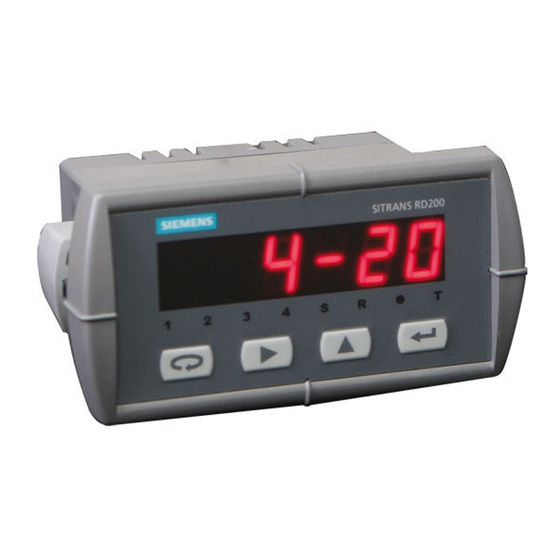
SITRANS RD200 Introduction SITRANS RD200 is a universal input, panel mount remote digital display for process instrumentation. It accepts a single input of current, voltage, thermocouple, or RTD signals, and the four front panel buttons make the setup and programming an easy task. -
Page 6: Specifications
Storage temperature range: -40 to +85 °C (-40 to +185 °F) • Relative humidity Relative humidity: 0 to 90% non-condensing Installation category Memory ● Non-volatile ● Stores settings for minimum of ten years if power is lost SITRANS RD200 Operating Instructions, 05/2019, A5E47629414-AA... -
Page 7: Programming
Auto and manual reset via front panel or PC • Latch or non-latch • Accuracy ±0.1% FS ±0.004 mA • All relays are certified only for use with equipment that fails in a state or under the rated maximums of the relays. SITRANS RD200 Operating Instructions, 05/2019, A5E47629414-AA... -
Page 8: Serial Communications
Type T, 0.1 °Res: ±1 °C in range -180.0 to +371 °C (±1.8 °F in range -199.9 • to+700 °F) RTD temperature 100 Ω RTD: ±1 °C in range -200 to +750 °C (±1 °F in range -328 to +1382 °F) SITRANS RD200 Operating Instructions, 05/2019, A5E47629414-AA... -
Page 9: Enclosure
● CE ● UL ● Note Testing was conducted on SITRANS RD200 meters installed through the covers of grounded metal enclosures with cable shields grounded at the point of entry representing installations designed to optimize EMC performance. SITRANS RD200 Operating Instructions, 05/2019, A5E47629414-AA... -
Page 10: Dimension Drawings
Dimension drawings RD200 Meter Dimensions - Side View ① Screw terminal connector [0.5 Nm (4.5 lb/in) tightening torque] SITRANS RD200 Operating Instructions, 05/2019, A5E47629414-AA... - Page 11 Dimension drawings RD200 Case Dimensions - Top View SITRANS RD200 Operating Instructions, 05/2019, A5E47629414-AA...
-
Page 12: Installing/Mounting
Unpacking Remove the meter from box. Inspect the packaging and contents for damage. Report damages, if any, to the carrier. If any part is missing or the meter malfunctions, please contact your local Siemens representative for assistance. Panel Mounting Instructions 1. - Page 13 Mounting screw ⑥ Mounting bracket ⑦ Panel cutout to DIN 43700 A= 92 mm (3.622") + 0.8 mm (+0.032") - 0.0 mm (+0.000") B= 45 mm (1.772") + 0.6 mm (+0.024") - 0.0 mm (+0.000") SITRANS RD200 Operating Instructions, 05/2019, A5E47629414-AA...
-
Page 14: Connection
The connectors label, affixed to the meter, shows the location of all connectors available with requested configuration. It also identifies the location of the RTD/TC selector switch. Connector Labeling for Two Relays and 24 V Supply SITRANS RD200 Operating Instructions, 05/2019, A5E47629414-AA... -
Page 15: Power Connections
The following figures show examples for current and voltage connections. There are no switches or jumpers to set up for current and voltage inputs. Setup and programming is performed through the front panel buttons. SITRANS RD200 Operating Instructions, 05/2019, A5E47629414-AA... - Page 16 The fuse limits the current to a safe level when it detects a fault condition, and automatically resets itself when the fault condition is removed. SITRANS RD200 Operating Instructions, 05/2019, A5E47629414-AA...
-
Page 17: Thermocouple And Rtd Connections
The RTD/TC selector switch must be set to the proper position for the meter to accept the selected temperature input. SEtu The input type is selected using the Setup ( ) menu. Selected thermocouple input must correspond to thermocouple sensor and wire type used. SITRANS RD200 Operating Instructions, 05/2019, A5E47629414-AA... - Page 18 Signal Connector ② Switch position Three-wire RTD input connections ① Signal connector ② Switch position ③ RTD sensor The meter accepts two, three, or four-wire RTDs. The three-wire RTD connection has built-in lead wire compensation. SITRANS RD200 Operating Instructions, 05/2019, A5E47629414-AA...
- Page 19 The four-wire RTD connection is similar to the three-wire. One of the leads of a four-wire RTD is not connected, and may be clipped off. The three-wire connection provides sufficient lead wire compensation to provide accurate readings even with long leads. SITRANS RD200 Operating Instructions, 05/2019, A5E47629414-AA...
-
Page 20: Serial Communication
RS232 serial adapter RS232 RS422/485 serial adapter RS422/485 SITRANS RD200 meter copy cable Meter-to-meter (for cloning purposes - copying pro- grammed settings from one meter to other meters) Relays and 24 V Output Connections Relay connections are made to a six-terminal connector labeled RELAY1, RELAY2 on Connector Labeling (Page 14). - Page 21 Connection 5.6 Serial Communication 4 to 20 mA Output Powered Externally ① mA out ② External power supply ③ Remote display chart recorder SITRANS RD200 Operating Instructions, 05/2019, A5E47629414-AA...
-
Page 22: Setup
Press Enter/Ack to access a menu or to accept a setting. Press and hold Right arrow and Menu for three seconds to access Advanced Features menu of the meter. SITRANS RD200 Operating Instructions, 05/2019, A5E47629414-AA... - Page 23 Set relay 2 action (automatic, latching, etc.) SEt2 Set2 Program set point 2 rSt2 Reset2 Program reset point 2 FLSF Fail-safe Enter Fail-safe menu FLS1 Fail-safe1 Set relay 1 fail-safe operation Enable fail-safe operation SITRANS RD200 Operating Instructions, 05/2019, A5E47629414-AA...
-
Page 24: Main Menu
Run Mode. Changes made to settings prior to pressing Enter/Ack are not saved. Changes to the settings are saved only after pressing Enter/Ack The display moves to the next menu every time a setting is accepted by pressing Enter/Ack SITRANS RD200 Operating Instructions, 05/2019, A5E47629414-AA... -
Page 25: Setting Numeric Values
• Visual alarm indication is available through front panel LEDs and the SITRANS RD Software. • The Analog Output menu is available if selected in the Advanced Features menu. 4 to 20 mA output option board is installed and set up at the factory. SITRANS RD200 Operating Instructions, 05/2019, A5E47629414-AA... -
Page 26: Setting Decimal Point
0-5, 1-5, 0-10, or ±10 V DC signals. The current input is capable of accepting any signal from -20 to 20 mA. Select current input to accept 0 to 20 or 4 to 20 mA signals. SITRANS RD200 Operating Instructions, 05/2019, A5E47629414-AA... - Page 27 • If tC is selected, the input signal must be connected to the appropriate input terminals and the RTD/TC selector switch must be set accordingly, see Thermocouple and RTD connections (Page 17). • For thermocouple inputs, allow at least 30 minutes warm-up time for meter to reach specified accuracy. SITRANS RD200 Operating Instructions, 05/2019, A5E47629414-AA...
- Page 28 – Off (relay and status LED disabled) ● Set point ● Reset point ● Fail-safe operation – On (enabled) – (disabled) ● Time delay – On delay (0-199 seconds) – Off delay (0-199 seconds) SITRANS RD200 Operating Instructions, 05/2019, A5E47629414-AA...
- Page 29 If set and reset points are programmed the same, relay will reset one count below set point. rLY2 is displayed. Press Enter/Ack to set up relay 2 or press Menu to exit and return to Run Mode. SITRANS RD200 Operating Instructions, 05/2019, A5E47629414-AA...
- Page 30 1. On1 is displayed. 8. Press Enter/Ack to proceed. 9. Press Up arrow to change digit and Right arrow to change active digit. 10. Press Enter/Ack to accept setting. SITRANS RD200 Operating Instructions, 05/2019, A5E47629414-AA...
-
Page 31: Relay And Alarm Operation
High alarm operation (Set > Reset) For Manual reset mode, Enter/Ack can be pressed at any time to turn off relay. For relay to turn back on, signal must go below setpoint, and then go above it. SITRANS RD200 Operating Instructions, 05/2019, A5E47629414-AA... - Page 32 Low alarm operation (Set < Reset) For Manual reset mode, Enter/Ack can be pressed at any time to turn off relay. For relay to turn back on, signal must go below setpoint, and then go below it. SITRANS RD200 Operating Instructions, 05/2019, A5E47629414-AA...
-
Page 33: Time Delay Operation
If the signal drops below the set point (high alarm) before the time delay has elapsed, the time delay timer resets and the relay does not change state. The same principle applies to the time delay. SITRANS RD200 Operating Instructions, 05/2019, A5E47629414-AA... - Page 34 6.4 Relay and Alarm Operation High alarm with fail-safe operation (Set > Reset) The relay coil is energized in non-alarm condition. In case of a power failure, the relay will go to alarm state. SITRANS RD200 Operating Instructions, 05/2019, A5E47629414-AA...
- Page 35 6.4 Relay and Alarm Operation Low alarm with fail-safe operation (Set < Reset) The relay coil is energized in non-alarm condition. In case of a power failure, the relay will go to alarm state. SITRANS RD200 Operating Instructions, 05/2019, A5E47629414-AA...
- Page 36 Setup 6.4 Relay and Alarm Operation Alternating pumps- mode: automatic (non-latching) SITRANS RD200 Operating Instructions, 05/2019, A5E47629414-AA...
-
Page 37: Scaling
Run Mode. Note For instructions on how to program numeric values, see Setting numeric values (Page 25). The Analog Output menu is also used to program the Sensor break value in mA. SITRANS RD200 Operating Instructions, 05/2019, A5E47629414-AA... - Page 38 The analog output reflects the display out of range conditions as follows: Input Condition Display Analog Output Underrrange Flashing -1999 3.00 mA Overrange Flashing 9999 21.00 mA Open TC or RTD Flashing open Sensor break value SITRANS RD200 Operating Instructions, 05/2019, A5E47629414-AA...
- Page 39 1. 9. Change display using the technique described in steps 7-8. 10. Repeat steps 6 to 10 for the second input value. 11. Press Enter/Ack to confirm settings and return to Run Mode. SITRANS RD200 Operating Instructions, 05/2019, A5E47629414-AA...
- Page 40 0.20 VDC 100°F (56°C) 50°F (28°C) Calibrating the SITRANS RD200 (CAL) Recalibration is recommended at least every twelve months. The meter can be calibrated to display the process in engineering units by applying the appropriate input signal and following the calibration procedure.
- Page 41 See "Recommended calibration points" above. After the meter accepts input 2, the display flashes the message CJr that indicates the meter is sensing the cold junction reference. This completes the recalibration procedure for the selected input. SITRANS RD200 Operating Instructions, 05/2019, A5E47629414-AA...
-
Page 42: Security
If the meter is password protected, the correct password must be entered in order to change parameters. Entering the correct four-digit number sets the password to 0000, disabling protection. Changes to the programmed parameter settings are allowed only with the password set to 0000. SITRANS RD200 Operating Instructions, 05/2019, A5E47629414-AA... -
Page 43: Advanced Features
Not available for process inputs FLtr Filet Set noise filter value byPS Bypass Set filter bypass value SErL Serial Set serial communication parameters Prot Protocol Enter the Protocol menu Select PDC protocol Modbus Select Modbus protocol SITRANS RD200 Operating Instructions, 05/2019, A5E47629414-AA... - Page 44 Display gain and offset for process inputs SErL Serial Display serial communication settings InFo Information Display software version and S/N information Note For instructions on how to program numeric values see Setting numeric values (Page 25). SITRANS RD200 Operating Instructions, 05/2019, A5E47629414-AA...
-
Page 45: Offset Adjustment
3. Press Up arrow to change the active digit and press Right arrow to advance to the next digit. 4. Press Ent/Ack to accept display setting. 5. Press Menu to exit at any time. SITRANS RD200 Operating Instructions, 05/2019, A5E47629414-AA... -
Page 46: Noise Filter Bypass (Byps)
Right arrow to advance to the next digit. 6. Press Enter/Ack to accept display settings. 7. Press Menu to exit at any time. SITRANS RD200 Operating Instructions, 05/2019, A5E47629414-AA... - Page 47 SITRANS RD200 can also be connected directly to another RD200 meter through a cable assembly (SITRANS RD200 Meter Copy Cable). This allows the user to copy all the settings from one meter to another, using the Copy function. See Meter copy function (Page 49).
- Page 48 5. Press Up arrow to scroll through the eight intensity levels. When the desired intensity level is displayed, press Ent/Ack to accept the setting. 6. Press Menu to exit at any time. SITRANS RD200 Operating Instructions, 05/2019, A5E47629414-AA...
-
Page 49: Sitrans Rd Software
6.7.4 SITRANS RD Software SITRANS RD software allows the SITRANS RD200 to be programmed from a PC and to act as a data logger. The software allows all setup parameters to be saved to a file for reporting, restoring, or programming other meters. -
Page 50: Meter Cloning Instructions
Do not connect the two meters to the same 4 to 20 mA loop while cloning. Internal calibration may be affected. 1. Connect the two meters using SITRANS RD200 meter copy cable or equivalent. Cable should not exceed 2.1 m (7 ft). - Page 51 • If meter is in operation and it is intended to accept only one input type (such as 4 to 20 mA), recalibration of other inputs is not necessary. • Allow the meter to warm up for at least 15 minutes before performing the internal calibration procedure. SITRANS RD200 Operating Instructions, 05/2019, A5E47629414-AA...
- Page 52 • Low and high input signals can be any valid values within the range of the meter. • Observe minimum input span requirements between input 1 and input 2. • Low input must be less than high input signal. SITRANS RD200 Operating Instructions, 05/2019, A5E47629414-AA...
-
Page 53: Troubleshooting
4. Press Enter/Ack button to access a displayed menu and Menu button to exit at any time. For a description of the diagnostics messages see Advanced Features (Page 43). SITRANS RD200 Operating Instructions, 05/2019, A5E47629414-AA... -
Page 54: Determining Software Version
), version ( ), and serial number ( ) information. Write down the information as it is displayed. Continue pressing Enter/Ack until all the information is displayed. 4. Press Menu to exit at any time. SITRANS RD200 Operating Instructions, 05/2019, A5E47629414-AA... -
Page 55: Operating
4. Press Right arrow to reset Max/Min while reading is being displayed. Max/ Min display readings are reset to actual reading. 5. Press Menu to exit Max/Min display. SITRANS RD200 Operating Instructions, 05/2019, A5E47629414-AA... -
Page 56: Factory Defaults
Input 2 20.00 mA diS2 Display 2 20.00 dd.dd Decimal point 2 places rLY1 Relay 1 Act1 Action 1 Automatic SEt1 Set 1 7.00 rSt1 Reset 1 6.00 rLY2 Relay 2 Act2 Action 2 Automatic SITRANS RD200 Operating Instructions, 05/2019, A5E47629414-AA... - Page 57 The minimum timeout allowed is saved to memory if a lower value is entered (for example, if user enters 0.00 with a baud rate of 300, 0.06 is saved). SITRANS RD200 Operating Instructions, 05/2019, A5E47629414-AA...
-
Page 58: Troubleshooting Tips
Display Software or other programs Serial adapter and cable Serial protocol selected Meter address and baud rate SITRANS Remote Display Software address and baud rate Other symptoms not described above Contact your local Siemens representative for assistance. SITRANS RD200 Operating Instructions, 05/2019, A5E47629414-AA... -
Page 59: Quick User Interface Reference Guide
Quick user interface reference guide SITRANS RD200 Operating Instructions, 05/2019, A5E47629414-AA... - Page 60 Menu or wait 10 seconds to return to Run Mode. Pressing Enter/Ack will disable the 10 second timeout and continuously display Max or Min. Note Press & hold Right arrow and Menu for 3 seconds to access Advanced Features Menu SITRANS RD200 Operating Instructions, 05/2019, A5E47629414-AA...
- Page 61 SITRANS RD200 Operating Instructions, 05/2019, A5E47629414-AA...
-
Page 62: Serial Communication Protocol
Serial communication protocol SITRANS RD200 PDC This section describes how to communicate with the SITRANS RD200 meter using the Serial Communication Protocol (PDC). The user should be familiar with serial communications and the meter. Refer to the instruction manuals for the meter and the serial communication adapters for setup and wiring instructions. -
Page 63: Command Packet Format
= 1 + not(0xEB) = 1 + 0x14 = 0x15 Therefore, the complete command packet that is sent = 0x01, “0026S015”, 0x03 In hex form = 0x01 0x30 0x30 0x32 0x36 0x53 0x30 0x31 0x35 0x03 SITRANS RD200 Operating Instructions, 05/2019, A5E47629414-AA... -
Page 64: Reply Packet Format
Error Code Description Message too short to be valid Checksum error Invalid command code Incorrect amount of data in the data field Invalid data in the data field EEPROM write error SITRANS RD200 Operating Instructions, 05/2019, A5E47629414-AA... -
Page 65: Read Only Commands
The reply data format is eight characters consisting of ‘+’ or ‘-’ followed by a number string. The number string is always seven characters, consisting of either six digits and a decimal point, or six digits with a leading zero if no decimal point is selected. SITRANS RD200 Operating Instructions, 05/2019, A5E47629414-AA... - Page 66 ‘0’ ‘1’ ‘.’ ‘2’ ‘3’ ‘4’ ‘ “ ‘ ‘9’ ‘4’ (0x02) (0x03) The reply data is eight characters consisting of the version code enclosed in quotation marks. An example is shown for “01.234” SITRANS RD200 Operating Instructions, 05/2019, A5E47629414-AA...
-
Page 67: No-Data Commands
2. Bypass and Filter values 3. Adjust value 4. Relay parameters (whether installed or not) 5. 4-20 mA output parameters (whether installed or not) 6. Serial parameters and address There is no data in the reply. SITRANS RD200 Operating Instructions, 05/2019, A5E47629414-AA... -
Page 68: Read/Write Commands
Code: 20 Description: Input Selection Parameters Table D- 20 Command: Read SOH (0x01) Meter Address Meter Address ‘2’ ‘0’ ‘9’ ‘E’ ETX (0x03) Table D- 21 Command: Write Meter Meter ‘2’ ‘0’ Check- Check- (0x01) Address Address (0x03) SITRANS RD200 Operating Instructions, 05/2019, A5E47629414-AA... - Page 69 0100 Type E thermocouple 0101 100 Ω Platinum RTD (385) 0110 100 Ω Platinum RTD (392) Example: To program meter 00 for Type J thermocouple in degrees F: Command packet: = 0x01, “00202380D1”, 0x03 SITRANS RD200 Operating Instructions, 05/2019, A5E47629414-AA...
- Page 70 Reply: Write and Read ‘2’ ‘2’ ‘+’ ‘0’ ‘0’ ‘0’ Check- Check- (0x02) (0x03) The data field is 7 characters consisting of “+000” followed by the value. Valid values are 000, and 002 to 199. SITRANS RD200 Operating Instructions, 05/2019, A5E47629414-AA...
- Page 71 ‘0’ ‘0’ Chec Chec (0x02 k-sum k-sum (0x03 The data field is 7 characters. The range is -199 to +199. Note that these values actually represent –19.9 to +19.9. The decimal point is implied. SITRANS RD200 Operating Instructions, 05/2019, A5E47629414-AA...
- Page 72 Meter Address ‘2’ ‘7’ Relay # Checksum Checksum ETX (0x03) Table D- 39 Command: Write Meter Meter ‘2’ ‘7’ Relay # ‘0’ ‘0’ Check- Check- (0x01) Address Address (0x03) ‘1‘ ‘1’ ‘2’ ‘3’ ‘4’ ‘7’ SITRANS RD200 Operating Instructions, 05/2019, A5E47629414-AA...
- Page 73 On Time Delay. The delay number is “+000” followed by the value in seconds. The range is 000 to 199. Note Relay numbers start with zero, but in the meter instruction manuals, relay numbering starts with one. SITRANS RD200 Operating Instructions, 05/2019, A5E47629414-AA...
- Page 74 Note that if a relay is not in a mode that allows acknowledgement, it will not be acknowledged. Note Relay numbers start with zero, but in the meter instruction manuals, relay numbering starts with one. SITRANS RD200 Operating Instructions, 05/2019, A5E47629414-AA...
- Page 75 ’6’ dddddd (no decimal) CAUTION Starting with SITRANS RD200 Version 3.000, if the presently selected input is either mA or V, writing a new decimal point using this command will immediately update the displayed decimal point also. SITRANS RD200...
- Page 76 If the 4-20 mA source selection is not Serial Communication(mA), this command will have no effect on the 4-20 mA output. The reply will be –99.99 to indicate this improper operation. Refer to Command 41 (next) for Modes. SITRANS RD200 Operating Instructions, 05/2019, A5E47629414-AA...
- Page 77 The data field is 7 characters consisting of “+0000” followed by the value. Valid values are 00, and 02 to 19. Note that this filtering is in addition to the display filtering. Note Filter Value cannot be accessed through the front panel menu. SITRANS RD200 Operating Instructions, 05/2019, A5E47629414-AA...
- Page 78 Limit Parameter ’0’ Sensor Break Value ’1’ Overrange Value ’2’ Underrange Value ’3’ Max Value Allowed ’4’ Min Value Allowed Note Only the Sensor Break Value can be accessed through the front panel menu. SITRANS RD200 Operating Instructions, 05/2019, A5E47629414-AA...
- Page 79 Command: Read SOH (0x01) Meter Address Meter Address ‘4’ ‘7’ ‘9’ ‘5’ (0x03) Table D- 62 Command: Write Meter Ad- Meter Address ‘4’ ‘7’ ‘+’ ‘0’ ‘0’ Chec Chec (0x01) dress ksum ksum (0x03 SITRANS RD200 Operating Instructions, 05/2019, A5E47629414-AA...
- Page 80 Select Linear (‘L’) or Exponent (‘E’) display mode. Linear: DisplayValue = (ADC_count * Gain) + Offset, Exponent: DisplayValue = ((ADC_count – Input_low)0.5 * Gain) + Offset, where Input_low, Gain, and Offset are user defined, either through scaling or external calibration. SITRANS RD200 Operating Instructions, 05/2019, A5E47629414-AA...
-
Page 81: Modbus Register Tables
Modbus register tables This section describes how to communicate with the SITRANS RD200 meter using the Modbus RTU Serial Communication Protocol. The user should be familiar with Modbus ® serial communication and the meter. Refer to the instruction manuals for the meter and the serial communication adapters for setup and wiring instructions. - Page 82 (0004– Only 40006 value point by itself will return 0xFFFF. 0005) 40007 6 Alarm Read 1 = In Alarm None Bits Mirror of 40002. (0006) both, 1 = relay Relay energized Write status Relays SITRANS RD200 Operating Instructions, 05/2019, A5E47629414-AA...
- Page 83 (000F) Scale Only to execute Volts Caution! See "Remote scaling procedure" remote in Register Notes below. scaling. 40101 Input Read None See Register Notes (Page 90). (0064) selection Write applicable SITRANS RD200 Operating Instructions, 05/2019, A5E47629414-AA...
- Page 84 (0069) Write Defined Valid only for process inputs. 9999 40107 Filter Read 0, 2 Unit-less Integer Display filtering. 0 = no filter- ing. New = old + ((new - (006A) Write old)/Filter) SITRANS RD200 Operating Instructions, 05/2019, A5E47629414-AA...
- Page 85 None Integer Changes to this register are saved but don’t take (006F) Address Write effect until next meter reset (Modbus command or power-up). Writing out of range data results in an address of 247. SITRANS RD200 Operating Instructions, 05/2019, A5E47629414-AA...
- Page 86 00D1) Volts of Volts 40212 fault values of 0 and 210 – 211 (000.0 1000, respectively, will be (00D2– used instead. This data to 300.0 00D3) represents the input SITRANS RD200 Operating Instructions, 05/2019, A5E47629414-AA...
- Page 87 Due to hardware variations, – actual output range is de- (0192) Write signed to be at least 1.00 to Sensor 23.00 mA. Writing out of range Break value data results in a value of 3.00 SITRANS RD200 Operating Instructions, 05/2019, A5E47629414-AA...
- Page 88 Integer 4-20mA out scaling. Rep- out – resents the mA output at (0199) Write Display 1 value without Output 1 decimal point. Writing out of range data results in a value of 23.99 mA. SITRANS RD200 Operating Instructions, 05/2019, A5E47629414-AA...
- Page 89 49108 (2390 – ters 2393) 49109 9108 – Mfg. Serial Read None ASCII 16 (max) characters indi- 9115 cating the manufacturing Number Only applicable charac- serial number information. 49116 (2394 – ters 239B) SITRANS RD200 Operating Instructions, 05/2019, A5E47629414-AA...
-
Page 90: Register Notes
Process value dis- Register 40001 Register 40102 Registers 40005 – played 40006 1.234 04D2 0003 3F9D – F3B6 12.34 04D2 0002 4145 – 70A4 123.4 04D2 0001 42F6 – CCCD -123.4 FB2E 0001 C2F6 – CCCD SITRANS RD200 Operating Instructions, 05/2019, A5E47629414-AA... - Page 91 – b. Write the desired values for the input, Input 1 & 2, for mA or volts. Note that the values written to SITRANS RD200 are (mA * 100) or (volts * 100) because of the meter’s input specifications (4 digit, 20.00 mA and 10.00 volt input ranges).
-
Page 92: Decimal Point
6 – 3 2 – 0 Function 00000000 Output Option 000 0 4-20 mA Data Source Relays Serial Comm., The data for the 4- bits 20 mA output is register 40412. 4-20 mA Unused Unused Unused SITRANS RD200 Operating Instructions, 05/2019, A5E47629414-AA... -
Page 93: Available Register Table
Available Register Table This table shows available registers for SITRANS RD200 with firmware version 3.xxx. RD200 Version 3. xxx 40001 to 40016 40301 to 40310 • • 40101 to 40113 40401 to 40412 • • 40201 to 40212 49101 to 49116 •... -
Page 94: Technical Support
In addition to our documentation, Siemens provides a comprehensive support solution at: ● Services & Support (http://www.siemens.com/automation/service&support) Personal contact If you have additional questions about the device, please contact your Siemens personal contact at: ● Partner (http://www.automation.siemens.com/partner) To find the personal contact for your product, go to "All Products and Branches" and select "Products &...