
Related Manuals for Bosch Rexroth IndraControl VR 21 Series


Summary of Contents for Bosch Rexroth IndraControl VR 21 Series
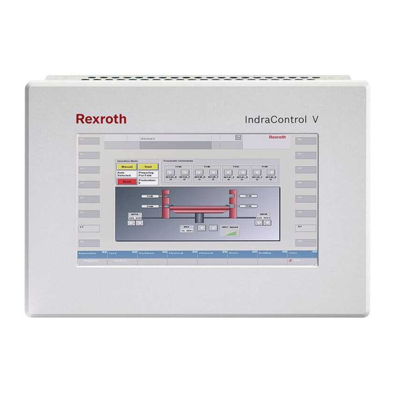
- Page 1 Electric Drives Linear Motion and and Controls Hydraulics Assembly Technologies Pneumatics Service Rexroth IndraControl R911339476 Edition 02 VR 21 Operating Panel Operating Instructions...
- Page 2 © Bosch Rexroth AG 2014 This document, as well as the data, specifications and other information set forth in it, are the exclusive property of Bosch Rexroth AG. It may not be repro- duced or given to third parties without its consent.
-
Page 3: Table Of Contents
VR 21 Bosch Rexroth AG Table of Contents Table of Contents Page About this Documentation..............1 Product Identification and Scope of Delivery........2 Product Identification................2 Scope of Delivery................... 2 Using the Safety Instructions..............3 Safety Instructions – Structure.............. 3 Explaining Signal Words and Safety Alert Symbol......... - Page 4 Bosch Rexroth AG VR 21 Table of Contents Page Assembly, Disassembly and Electrical Installation......13 10.1 Housing Dimensions................13 10.1.1 Front View.................... 13 10.1.2 Overview of Housing Dimensions - Side View........14 10.2 Installation Notes................. 14 10.3 Mounting Cut-Out................15 10.4...
- Page 5 VR 21 Bosch Rexroth AG Table of Contents Page Service and Support................23 Index....................25 DOK-SUPPL*-VR21**.01**-IT02-EN-P...
- Page 6 Bosch Rexroth AG VR 21 DOK-SUPPL*-VR21**.01**-IT02-EN-P...
-
Page 7: About This Documentation
VR 21 Bosch Rexroth AG About this Documentation 1 About this Documentation Overview – target groups and product phases The activities, product phases and target groups that refer to the present docu- mentation are marked in red color in the following figure. -
Page 8: Product Identification And Scope Of Delivery
Please email your feedback on the documentations to Feed- back.Documentation@boschrexroth.de. Directly insert comments in the elec- tronic PDF document and send the PDF file to Bosch Rexroth. 2 Product Identification and Scope of Delivery 2.1 Product Identification The type plate is located on the rear panel. -
Page 9: Using The Safety Instructions
VR 21 Bosch Rexroth AG Using the Safety Instructions Six mounting brackets including tool ● 24 V female connector strip ● 3 Using the Safety Instructions 3.1 Safety Instructions – Structure The safety instructions are structured as follows: Consequences and... -
Page 10: Symbols Used
Tips are displayed as follows: This is a tip. 4 Intended Use The IndraControl VR 21 devices by Bosch Rexroth are machine operator panels that can, depending on the application, visualize control data and trigger func- tions at the machine. -
Page 11: Spare Parts, Accessories And Wear Parts
VR 21 Bosch Rexroth AG Spare Parts, Accessories and Wear Parts Packaging and food processing machines ● Printing machines and paper converting machines ● Machine tools ● Wood processing machines ● The machine operator panels may only be operated under the mounting and in- stallation conditions, the position, and the ambient conditions (temperature, de- gree of protection, humidity, EMC etc.) specified in this documentation. -
Page 12: Ambient Conditions
Bosch Rexroth AG VR 21 Technical Data 6 Ambient Conditions In operation Transport Storage Max. ambient +0 ℃ to +50 ℃ -25 ℃ to +70 ℃ temperature Humidity Min. relative humidity: 20 Min. relative humidity: 20 Min. relative humidity: 20 % Max. -
Page 13: Vr 21 Multitouch
VR 21 Bosch Rexroth AG Technical Data VR2104 Singletouch VR2107 Singletouch VR2109 Singletouch Front panel material Aluminium, brushed, naturally anodized Enclosure rating Front panel IP 65 according to DIN EN 60 529, rear side IP 20 Central processing unit ARM Cortex™-A8, 800 MHz with real-time clock... -
Page 14: Standards
Bosch Rexroth AG VR 21 Standards VR2107 Multitouch VR2109 Multitouch Voltage supply DC 24 V (use a 24 V power supply unit according to DIN EN 60742, classification VDE 0551, for example the power supply unit VAP01.1H-W23-024-010-NN, part number R911171065) Current consumption 0.4 A (typically at 24 V) -
Page 15: Ce Marking
VR 21 Bosch Rexroth AG Standards 8.3 CE Marking 8.3.1 Declaration of Conformity The electronic products that are described in the present instructions, comply with the requirements and the target of the following EU directive and with the following harmonized European standards:... -
Page 16: Interfaces
Bosch Rexroth AG VR 21 Interfaces Loss of UL/CSA conformity due to modifications to the device. The UL and CSA marking is only valid for the device in its delivery status. After modifying the device, the UL and CSA conformity is to be verified. -
Page 17: Dc 24 V Voltage Supply
VR 21 Bosch Rexroth AG Interfaces Malfunctions due to insufficient shielding! NOTICE Use only shielded cables and metallic or conductive connector/coupling covers with large-area shield support. 9.3 DC 24 V Voltage Supply Cables with a cross section of 0.75 to 2.5 mm can be connected to the connec- tion terminal. -
Page 18: Ethernet Interface X5
Bosch Rexroth AG VR 21 Interfaces Not all USB devices are recognized. The operating system does not support all USB devices. Devices that require a special USB driver, which is not integrated in the system, cannot be operated at the USB interfaces. -
Page 19: Assembly, Disassembly And Electrical Installation
VR 21 Bosch Rexroth AG Assembly, Disassembly and Electrical Installation Removing the memory card Insert the memory card in the operating device until it engages. Remove the un- locked memory card. 10 Assembly, Disassembly and Electrical Installation 10.1 Housing Dimensions 10.1.1 Front View... -
Page 20: Overview Of Housing Dimensions - Side View
Bosch Rexroth AG VR 21 Assembly, Disassembly and Electrical Installation 10.1.2 Overview of Housing Dimensions - Side View ① ③ Front panel See the following table for mounting ② Mounting surface 1 to 6 mm depth Fig. 10-2: Side view (sample illustration) -
Page 21: Mounting Cut-Out
VR 21 Bosch Rexroth AG Assembly, Disassembly and Electrical Installation Loss of degree of protection IP 65! The housing in which the operator display is installed, has to fulfil the following conditions: Free from impurities ● Sufficient mechanical strength and flatness ●... -
Page 22: Mounting Dimensions
Bosch Rexroth AG VR 21 Assembly, Disassembly and Electrical Installation 10.4 Mounting Dimensions Mounting cut-out Fig. 10-4: Mounting cut-out Device ① ② VR2104 92 mm 132 mm VR2107 142 mm 203 mm VR2109 170 mm 255 mm Tab. 10-3: Housing dimensions: IndraControl VR 21 front 10.5 Disassembly... -
Page 23: Connecting The Functional Earth (Fe)
VR 21 Bosch Rexroth AG Assembly, Disassembly and Electrical Installation Use a cable with finely stranded cores with a minimum cross section of 0.75 mm and a maximum cross section of 2.5 mm for the supply voltage. Comply with the following torques at the connectors: Screw terminal of the terminals: 0.22 Nm (minimum) up to 0.25... -
Page 24: Commissioning
Bosch Rexroth AG VR 21 Device Description Fig. 10-6: Functional earth connection 11 Commissioning The product is ready for operation immediately The IndraControl VR 21 is configured using the cockpit tool. The cockpit tool is described in the project planning manual "Rexroth IndraControl V Devices Ope- rating Systems"... -
Page 25: Control And Display Elements
VR 21 Bosch Rexroth AG Device Description 12.2 Control and Display Elements 12.2.1 Display Poisoning or chemical burns due to damaged WARNING display If the display is damaged, avoid direct skin contact, choking, breathing in of leaking liquid or gas! -
Page 26: Error Causes And Elimination
14.2 Display The backlight is subject to wear (see chapter 5.2 "Wear Parts" on page A fading backlight causes a progressive deterioration display readability, so that a replacement is necessary. For further information please contact the Bosch Rexroth Service. 20/29 DOK-SUPPL*-VR21**.01**-IT02-EN-P... -
Page 27: Cleaning Notes
VR 21 Bosch Rexroth AG Ordering Information 14.3 Cleaning Notes The surface of the foil as well as the display NOTICE seal are dissolved by solvents! Do not use any solvents (e. g. diluents)! ● No high pressure cleaning devices are to be used! ●... -
Page 28: Type Code Vr21Xx.01
Bosch Rexroth AG VR 21 Disposal 15.2 Type Code VR21xx.01 Short text column 1 2 3 4 5 6 7 8 9 0 1 2 3 4 5 6 7 8 9 0 1 2 3 4 5 6 7 8 Example: V R 2 1 0 4 . -
Page 29: Packaging
VR 21 Bosch Rexroth AG Service and Support Bosch Rexroth AG Electric Drives and Controls Bürgermeister-Dr.-Nebel-Straße 2 D-97816 Lohr am Main, Germany 16.2 Packaging The packaging materials consist of cardboard, plastic material, wood or expan- ded polystyrene (EPS). The packaging materials can be recycled without any problem. - Page 30 Bosch Rexroth AG VR 21 24/29 DOK-SUPPL*-VR21**.01**-IT02-EN-P...
-
Page 31: Index
VR 21 Bosch Rexroth AG Index Index Accessories........5 Installation notes......14 Ambient conditions......6 Intended use........4 Assembly........13 Interfaces........10 Ethernet interface....12 X9, X10 USB interfaces.... 11 Backlight......... 5 Maintenance......... 20 Maintenance notes....... 21 CE marking........9 Memory card......... - Page 32 Bosch Rexroth AG VR 21 Index Target groups......... 1 Technical data........ 6 Voltage supply......11 Wear parts......... 5 Touchscreen......... 19 Type code........22 Type plate........2 UL/CSA Certified......9 USB interfaces......11 Use, intended......... 4 Voltage supply......11 Voltage supply (DC 24 V)....11 VR 21 variants.......
- Page 33 VR 21 Bosch Rexroth AG 27/29 DOK-SUPPL*-VR21**.01**-IT02-EN-P...
- Page 34 Bosch Rexroth AG VR 21 28/29 DOK-SUPPL*-VR21**.01**-IT02-EN-P...
- Page 35 VR 21 Bosch Rexroth AG Notes...
- Page 36 Bosch Rexroth AG Electric Drives and Controls P.O. Box 13 57 97803 Lohr, Germany Bgm.-Dr.-Nebel-Str. 2 97816 Lohr, Germany Tel. +49 9352 18 0 +49 9352 18 8400 www.boschrexroth.com/electrics DOK-SUPPL*-VR21**.01**-IT02-EN-P...