ABB C1900 Operating Manual
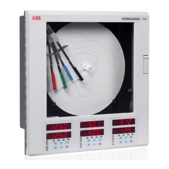
Circular chart recorder
Hide thumbs
Also See for C1900:
- Operating manual (44 pages) ,
- Installation manual (28 pages) ,
- User manual (20 pages)
Table of Contents
Advertisement
Quick Links
—
A B B M E A S U R E M E N T & A N A LY T I C S | O P E R AT I N G G U I D E | I M/C 1 9 0 0 - O G R R E V. L
C1900
Circular chart recorder
For more information
—
C1900
Further publications are available for free download
circular chart recorder
from:
www.abb.com/recorders
or by scanning this code:
Measurement made easy
Data Sheet
C1900
Circular chart recorder
Quick Reference Guide
C1900
Circular chart recorder
Installation Guide
C1900
Circular chart recorder and
recorder / controller
Programming Guide
C1900
Circular chart recorder
Operating Instructions
C1900
Circular chart recorder and
recorder/controller
User Guide
C1900
Circular chart recorder and
recorder/controller
Search for or click on
DS/C1900R-EN
IM/C1900-QR
IM/C1900-INS
IM/C1900-PGR
IM/C1900-MOD
IM/C1900-ADV
Advertisement
Table of Contents

Related Manuals for ABB C1900


Summary of Contents for ABB C1900
- Page 1 A B B M E A S U R E M E N T & A N A LY T I C S | O P E R AT I N G G U I D E | I M/C 1 9 0 0 - O G R R E V. L C1900...
- Page 2 Use of instructions Health and safety To ensure that our products are safe and without risk to health, Warning – an instruction that draws attention to the risk of injury or death. the following points must be noted: • The relevant sections of these instructions must be read Caution –...
-
Page 3: Table Of Contents
CONTENTS 1 INTRODUCTION Section Page The documentation for the C1900 series of circular chart recorders is shown in Fig. 1.1. The , including Standard Manuals the data sheet, are supplied with all instruments. The INTRODUCTION ............1 supplied depend on the specification of Supplementary Manuals the instrument. -
Page 4: Setting Up
2 SETTING UP 2.1 Instrument Power-up – Fig. 2.1 and 2.2 1914 J Caution. Ensure that all connections, especially to the tESt earth stud, are made correctly. a) Check that the input sensors are installed correctly. Instrument Test identifies the instrument type, e.g. 1914J –... -
Page 5: Power-Up Error Codes
2 SETTING UP… 2.1.1 Power-up Error Codes If any of the power-up tests fail (see Fig. 2.2), error codes are displayed to identify the fault. Refer to Fig. 2.3 for error code interpretations. A––––F Configuration and battery-backed RAM errors –2–4–– Calibration errors Code Error... -
Page 6: Fitting The Chart
…2 SETTING UP 2.2 Fitting the Chart – Fig. 2.4 2.3 Fitting the Pen Capsule(s) – Fig. 2.5 Raise pens Raise pens Lift the chart clamp and remove the chart Gently pull the arm off the bracket – see Note Note. -
Page 7: Displays & Controls
3 DISPLAYS & CONTROLS The displays, LED indicators and operation/programming controls are located on the faceplate on the front panel of the instrument – see Fig 3.1. 8. 8 . 8 . 8 . 8 . 8 . Displays 3.1 Displays and LED Indicators – Fig. 3.1 8. -
Page 8: Use Of Controls
…3 DISPLAYS & CONTROLS 3.2 Use of Controls – Fig. 3.2(a) to (f) Lift/Lower pen on alternate operations Page 1 Page 2 Frame 1 Frame 1 Frame 2 Frame 2 Notes. Frame 3 Frame 3 • The key can be enabled or disabled in the Set Up Return from Frame 4... -
Page 9: Operation
4 OPERATION Fig. 4.1 Summary of Operating Level... -
Page 10: Input Error Messages
…4 OPERATION The instrument has dedicated in the – see Sections. 4.1 to 4.4. These pages are used for general Operating Pages OPERATOR LEVEL monitoring of the process measurements and are not affected by the security system which inhibits access to the PROGRAMMING only –... -
Page 11: Operating
4 OPERATION… 4.2 Operating Page Displays Faceplate 1 for channels 1 and 2 Faceplate 2 for channels 3 and 4 Process Variable 1 (PV1) Process Variable 3 (PV3) 100. 3 300. 3 200. 5 Process Variable 2 (PV2)* Process Variable 4 (PV4)* 400. -
Page 12: Alarm Acknowledge Page
…4 OPERATION 4.3 Alarm Acknowledge Page 4.3.3 Using the Alarm Acknowledge Page No Alarm Active 4.3.1 Alarm Indications – Fig. 4.3 No LED indicators illuminated. The definitions for alarm states (on, off or flashing) are detailed in Fig. 4.3. 4.3.2 Acknowledging Alarms Note. -
Page 13: Totals
4 OPERATION… 4.4 Totals Page Displays This page is omitted from both faceplates if the is not fitted. The page is also omitted from faceplate 1 if both Totals Totalizer Option 1 and 2 are set to and from faceplate 2 if both Totals 3 and 4 are set to –... -
Page 14: Access To Configuration Levels
…4 OPERATION 4.5 Access to Configuration Levels A security system is used to prevent tampering with the programmed parameters by utilizing a password giving access to all programming pages – refer to the Programming Manual Security Code Security Code Page the pen adjustment SECOdE 100. -
Page 15: Simple Fault Finding
5 SIMPLE FAULT FINDING Symptom Possible Cause Action Does not power up a) Internal fuse (if fitted) is blown a) Check wiring, rectify fault and replace fuse b) Internal power switch (if fitted) is OFF b) Turn power switch ON c) Power supply connections are incorrect c) Check connections Chart does not appear to move... -
Page 16: Spares List
ER/C Type Chart (J or R in Code Number) – Event Pen ....................C1900/0078 PX105 and PXR105 Type Chart (K or S in Code Number) – Standard Pen ..............C1900/0075 PX105 and PXR105 Type Chart (K or S in Code Number) – Event Pen ................. C1900/0077 Fuses 24V .................................... - Page 17 NOTES...
- Page 18 NOTES...
- Page 19 Sales Service Software...
- Page 20 We reserve the right to make technical changes or modify the contents of this document without prior notice. With regard to purchase orders, the agreed particulars shall prevail. ABB does not accept any responsibility whatsoever for potential errors or possible lack of information in this document.