
Related Manuals for Sony MEU-WX1


Summary of Contents for Sony MEU-WX1
- Page 1 4-098-710-16 (1) Multiformat Engine Unit Operating Instructions MEU-WX1 © 2003 Sony Corporation...
- Page 2 In the event of a malfunction or when maintenance is commercial environment. This equipment generates, necessary, consult an authorized Sony dealer. uses, and can radiate radio frequency energy and, if not installed and used in accordance with the instruction...
- Page 3 Attention-when the product is installed in Rack: 1.Prevention against overloading of branch circuit When this product is installed in a rack and is supplied power from an outlet on the rack, please make sure that the rack does not overload the supply circuit. 2.Providing protective earth When this product is installed in a rack and is supplied power from an outlet on the rack, please confirm that the...
- Page 4 Öffnen Sie niemals das Gehäuse, und überlassen Sie Wartungsarbeiten stets nur einem Fachmann. Dans le cas d'une défaillance ou de nécessité d'entretien, consulter un revendeur Sony autorisé. Sollten am Gerät Probleme auftreten oder eine Wartung erforderlich werden, wenden Sie sich an einen Cet appareil contient des substances susceptibles de autorisierten Sony -Händler.
- Page 5 Nel caso di malfunzionamenti o di necessarie En caso de mal funcionamiento o cuando sea necesario riparazioni dell'apparecchio, consultare un rivenditore el servicio de mantenimiento, consulte a su proveedor autorizzato Sony. Sony. Questo apparecchio contiene sostanze che possono Esta unidad contiene sustancias que pueden contaminar inquinare l'amibiente se non vengono smaltite con le el medio ambiente si no se desecha adecuadamente.
- Page 6 Pour les clients européens Para los usuarios en Europa Ce produit portant la marque CE est conforme à la fois Este producto con la marca CE cumple con las à la Directive sur la compatibilité électromagnétique Directivas EMC (89/336/CEE) y de Baja Tensión (73/ (EMC) (89/336/CEE) et à...
-
Page 8: Table Of Contents
Table of Contents Precaution .............. 9 On Safety ............9 On Installation ............ 9 On Cleaning ............9 On Repacking ............. 9 On Mounting on a Rack ........9 On Fan Error ............9 Features ..............9 Location and Function of Parts and Controls .. 11 Front Panel ............ -
Page 9: Precaution
• Disconnect the power cord from the AC outlet by grasping the plug, not by pulling the cord. • The socket-outlet shall be installed near the equipment The MEU-WX1 is a Multiformat Engine Unit which is and shall be easily accessible. used with an LCD monitor for professional use. - Page 10 Input Scan setting You can set the display size to 0% or 5% over scan Analog RGB/component input connectors mode. Analog RGB or component (Y, P ) signals from H/V delay mode video equipment can be input through these connectors. The horizontal and vertical sync signals can be Y/C input connectors monitored simultaneously in the H/V delay mode.
-
Page 11: Location And Function Of Parts And Controls
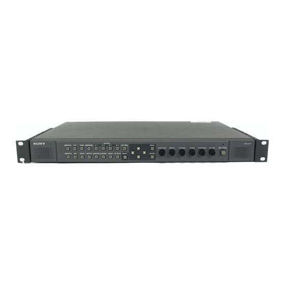
Location and Function of Parts and Controls Front Panel a POWER switch and indicator h Menu operation buttons Press to turn on the power. The indicator turns on. Press Displays or sets the on-screen menu. again to turn off the power. M/m/</, (arrow) buttons b VOLUME control Select the menu or make various adjustments. - Page 12 n MARKER button RGB button: to monitor the signal through the video input (RGB) connectors. When the button is pressed, an area marker is displayed. Set the safety area size in the menu screen. COMPONENT button: to monitor the signal o BLUE ONLY button through the video input (component) connectors.
-
Page 13: Input Signals And Adjustable/Setting Items
Input signals and adjustable/ setting items Input signal Item Video, Y/C B & W Component Computer CONTRAST* BRIGHT* × × × × CHROMA* × × × × × × × × × PHASE* (NTSC) × × × APERTURE COLOR TEMP AUTO CHROMA/ ×... -
Page 14: Rear Panel
Rear Panel a G/Y/COMPOSITE connector (BNC)* When the cable is connected to this connector, the Input connector for composite, component Y 75-ohm termination of the input is automatically (luminance) and G of RGB signals. released, and the signal input to the IN connector is output from this connector. -
Page 15: Installing To The Rack
j AUDIO MONITOR OUT connector (stereo Installing to the Rack mini jack) The audio signal which is selected by the input select button on the front panel is output. Remove the four legs from the bottom. When an analog video signal is input, the signal which is set in the USER CONFIG menu is output (see page 12 and 26). -
Page 16: Connections
To Connect the AC Power Cord Connections Connect the supplied AC power cord as illustrated. Plug the AC power cord into the AC IN socket on To Connect an LCD Monitor the rear panel. Then, attach the AC plug holder (supplied) to the AC power cord. -
Page 17: Attaching The Input Adaptor
Attaching the Input Selecting the Default Adaptor Settings Before attaching the input adaptor, disconnect the power When you turn on the unit for the first time after cord. purchasing it, select the area where you intend to use this Attach the input adaptor to the optional input slot after unit from among the options. - Page 18 4 If ASIA EXCEPT JAPAN is selected: Customers who will use this unit in the shaded areas shown in the map below should select NTSC AREA. Other customers should select PAL AREA. Press the POWER switch. The power is turned on and the SELECT SETTING screen appears.
-
Page 19: Selecting The Menu Language
Press the M or m button to select “LANGUAGE,” Selecting the Menu then press the , or ENTER button. The selected item is displayed in yellow. Language Press the M or m button to select a language, then press the ENTER button. You can select one of seven languages (English, The menu changes to the selected language. -
Page 20: Using The Menu
Note Using the Menu If the menu consists of multiple pages, press M or m to go to the desired menu page. The unit is equipped with an on-screen menu for making various adjustments and settings such as picture control, Make the setting or adjustment on an item. -
Page 21: Adjustment Using The Menus
INPUT SETTING Adjustment Using the When selecting the COMPUTER input Menus SUB CONTROL INPUT SETTING Items USER CONFIG MATRIX The screen menu of this monitor consists of the following items. COMP LEVEL NTSC SETUP STATUS (the items indicate the GAMMA current settings.) FORMAT DISP LANGUAGE... -
Page 22: Adjusting And Changing The Settings
• Power saving Adjusting and Changing the • Display Settings • Multi Format Engine • Option A • Option B STATUS menu The STATUS menu is used to display the current status COLOR TEMP/BAL menu of the unit. The following items are displayed: The COLOR TEMP/BAL menu is used for adjusting the When selecting an input other than COMPUTER picture white balance. -
Page 23: User Control Menu
USER CONTROL menu Submenu Setting The USER CONTROL menu is used for adjusting the SUB CONTROL You can finely adjust the picture. adjustment range of the following controls on the front panel; Items that cannot be adjusted depending on the input CONTRAST, BRIGHT, CHROMA signal are displayed in blue. - Page 24 When selecting the COMPUTER input Submenu Setting * The menu cannot be adjusted. SUB CONTROL You can finely adjust the adjustment range of the following U S E R C O N T R O L ( 2 / 3 ) R r controls on the front panel;...
- Page 25 About the Preset Memory No. Note This unit has 18 types of preset for the signals connected to the computer input terminal (the preset memory). Set the same polarity as the sync signal (horizontal/ When a preset signal is input, the unit automatically vertical) as one of the "Preset signals"...
-
Page 26: User Config Menu
USER CONFIG menu Submenu Setting You can select a language, etc. MATRIX Applied to 480/60I or 480/60P signal. Select 601 or 709. U S E R C O N F I G ( 1 / 2 ) R r xM AT R I X COMP LEVEL Select the component level from ·... - Page 27 Submenu Setting Submenu Setting MARKER When the frame of the film is SCAN Sets the scan size of the picture. displayed on the screen, select the Select from “FULL” and “ZOOM” aspect ratio according to the film. mode. The displayed picture differs •...
- Page 28 When a 4:3 monitor is used Output Input ZEROSCAN NORMAL SCAN FULL ZOOM (5% OVERSCAN) SD signal HD singal When a 15:9 monitor is used Output Input ZEROSCAN NORMAL SCAN FULL ZOOM (5% OVERSCAN) SD signal HD Signal Adjustment Using the Menus...
-
Page 29: Remote Parallel Menu
REMOTE PARALLEL menu OPTION CONFIG menu Select the REMOTE connector pins for which you want Sets an optional input adaptor. to change the function. You can assign various functions to 1 to 4 pins and 6 to O P T I O N C O N F I G O P T I O N A 8 pins. -
Page 30: Troubleshooting
Troubleshooting Specifications This section may help you isolate the cause of a problem Picture performance and as a result, eliminate the need to contact technical Over scan 0%/5% support. • The display is colored in green or purple t Select Input/output connectors the correct input by pressing RGB or COMPONENT button. - Page 31 Computer audio input jack Recommended temperature Stereo mini jack (1), –5 dBu, 47 20 °C to 30 °C (68 °F to 86 °F) kilohms or higher Humidity 30% to 85% (no condensation) Optional input slot Pressure 700 hPa to 1060 hPa 2 slots Storage and transport conditions Signal format:...
- Page 32 Video signal formats The unit is applicable to the following signal formats. Input System Total lines Active lines Frame rate* Scanning format Aspect ratio Signal standard 575/50I (PAL) 2:1 interlace 16:9/4:3 EBU N10 (PAL: ITU-R BT.624) 480/60I (NTSC) 2:1 interlace 16:9/4:3 SMPTE 253M (NTSC: SMPTE 170M)
-
Page 33: Dimensions
When an optional input adaptor is installed, the unit is Dimensions applicable to the following signal formats. When BKM-220D/243HS is installed Front Input System Signal standard BKM-220D BKM-243HS 575/50I ITU-R BT.656 480/60I SMPTE 259M 1080/24PsF SMPTE 292M × 383.6 (15 1080/50I SMPTE 292M ×... - Page 34 Sony Corporation...