ABB ACS800-U7 Hardware Manual
Acs800
45 to 560 kw; 50 to 600 hp
Hide thumbs
Also See for ACS800-U7:
- Firmware manual (214 pages) ,
- Hardware manual (96 pages) ,
- Manual (42 pages)

Related Manuals for ABB ACS800-U7


Summary of Contents for ABB ACS800-U7
- Page 1 ACS800 Hardware Manual ACS800-07 Drives (45 to 560 kW) ACS800-U7 Drives (50 to 600 hp)
-
Page 2: List Of Related Manuals
You can find manuals and other product documents in PDF format on the Internet. See section Document library on the Internet on the inside of the back cover. For manuals not available in the Document library, contact your local ABB representative. - Page 3 ACS800-07 Drives 45 to 560 kW ACS800-U7 Drives 50 to 600 hp Hardware Manual 3AFE64702165 Rev H EFFECTIVE: 2012-09-19 2012 ABB Oy. All Rights Reserved.
-
Page 5: Safety Instructions
Safety instructions What this chapter contains This chapter contains the safety instructions which you must follow when installing, operating and servicing the drive. If ignored, physical injury or death may follow, or damage may occur to the drive, the motor or driven equipment. Read the safety instructions before you work on the unit. -
Page 6: Installation And Maintenance Work
Installation and maintenance work These warnings are intended for all who work on the drive, motor cable or motor. WARNING! Ignoring the following instructions can cause physical injury or death, or damage to the equipment:. • Only qualified electricians are allowed to install and maintain the drive. •... -
Page 7: Grounding
• Depending on the external wiring, dangerous voltages [115 V, 220 V or 230 V] may be present on the terminals of relay outputs RO1 to RO3 or on the optional AGPS board (Prevention of unexpected start-up). • The Prevention of unexpected start-up function (option +Q950 does not remove the voltage from the main and auxiliary circuits. -
Page 8: Mechanical Installation And Maintenance
Mechanical installation and maintenance These instructions are intended for all who install and service the drive. WARNING! Ignoring the following instructions can cause physical injury or death, or damage to the equipment: • Cover the drive when installing to ensure that dust from borings and grindings or foreign objects do not enter the drive. -
Page 9: Operation
Operation These warnings are intended for all who plan the operation of the drive or operate the drive. WARNING! Ignoring the instructions can cause physical injury or death or damage to the equipment. • Before adjusting the drive and putting it into service, make sure that the motor and all driven equipment are suitable for operation throughout the speed range provided by the drive. -
Page 10: Permanent Magnet Synchronous Motor
Permanent magnet synchronous motor These are additional warnings concerning permanent magnet synchronous motor drives. Ignoring the instructions can cause physical injury or death, or damage to the equipment. Installation and maintenance work WARNING! Do not work on the drive when the permanent magnet synchronous motor is rotating. -
Page 11: Table Of Contents
Table of contents List of related manuals ............2 Safety instructions What this chapter contains . - Page 12 Additional requirements for the braking applications ......42 Additional requirements for ABB high-output and IP23 motors ....42 Additional requirements for non-ABB high-output and IP23 motors .
- Page 13 Armored cable / shielded power cable ........54 Power factor compensation capacitors .
- Page 14 Motor control and I/O board (RMIO) What this chapter contains ............77 Note on optional terminal block X2 .
- Page 15 Replacing the additional fan at the lower part of the cubicle (R6 with du/dt filter, +E205) ..........98 Replacing the cabinet fans (frame size R8 only) .
- Page 16 Providing feedback on ABB Drives manuals ........
-
Page 17: Introduction To The Manual
Introduction to the manual What this chapter contains This chapter describes the intended audience and contents of the manual. It contains a flowchart of steps in checking the delivery, installing and commissioning the drive. The flowchart refers to chapters/sections in this manual and other manuals. -
Page 18: Contents
Contents The chapters of this manual are briefly described below. Safety instructions give safety instructions for the installation, commissioning, operation and maintenance of the drive. Introduction to the manual introduces this manual. Operation principle and hardware description describes the drive. Mechanical installation shows how to move and unpack the delivery and how to fasten the cabinet to the floor. -
Page 19: Installation And Commissioning Flowchart
If the converter has been non-operational for more than one year, the converter DC link Only intact units may be started up. capacitors need to be reformed. Ask ABB for instructions. Check the installation site. Mechanical... -
Page 20: Terms And Abbreviations
Terms and abbreviations Term/Abbreviation Definition ABRC Brake chopper control board ADPI Diagnostics and panel interface board AGDR Gate driver control board AGPS Power supply board for IGBT gate driver boards. Used in implementation of the optional Prevention of unexpected start-up function. AIBP Input bridge protection board AIMA... -
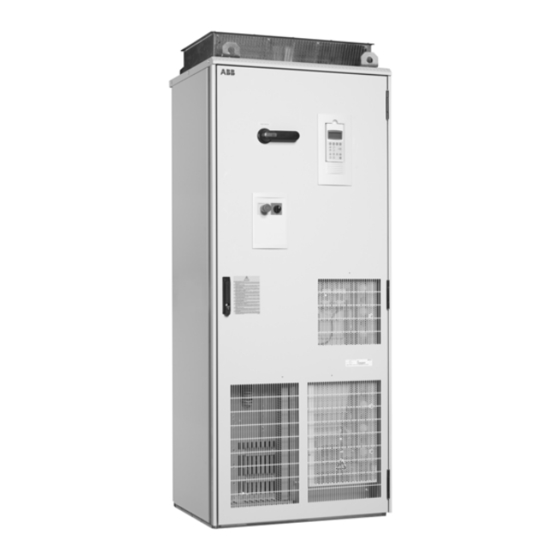
Page 21: Operation Principle And Hardware Description
Operation principle and hardware description What this chapter contains This chapter describes the construction and operating principle of the drive in short. Product overview The ACS800-07/U7 is a cabinet-installed drive for controlling AC motors. IP21/22 (UL type 1) *Line contactor Control panel Switch fuse (main Switch fuse handle... - Page 22 IP21/22 See page Drive module RMIO Additional fan (not in all types) View of frame size R6 without shrouds Power cable terminals See page Drive module RMIO View of frame size R5 without shrouds Power cable terminals Operation principle and hardware description...
-
Page 23: Type Designation Key
Type designation key The type designation key contains information on the specifications and configuration of the drive. The first digits from left express the basic configuration (eg, ACS800-07-0170-5). The optional selections are given thereafter, separated by + signs (eg, +E202). The main selections are described below. Not all selections are available for all types. - Page 24 Selection Alternatives Cabinet options +G300 cabinet heater (external supply) +G304 115 VAC control voltage +G307 terminals for external control voltage (UPS) +G313 output for motor heater (external supply) +G330 halogen-free materials and control wiring +G338 wire marking class A1 +G339 wire marking class A2 +G340 wire marking class A3...
-
Page 25: Main Circuit And Control
Main circuit and control Door switches The following switches are mounted on the cabinet door: Operating switch (units with main Emergency stop button contactor only) (optional) “START” position closes the main contactor; “ON” position keeps the main contactor closed; “OFF” position opens the main contactor. -
Page 26: Diagram
Diagram This diagram shows the control interfaces and the main circuit of the drive. Motor Optional module 1: RMBA, RAIO, control and RDIO, RDNA, RLON, RPBA, RCAN, I/O board RCNA, RETA, RRIA or RTAC (RMIO) Optional module 2: RTAC, RAIO, RRIA External control via or RDIO analogue/digital... -
Page 27: Printed Circuit Boards
Printed circuit boards The drive contains the following printed circuit boards as standard: • main circuit board (AINT) • motor control and I/O board (RMIO) with a fibre optic link to the AINT board • input bridge control board (AINP) •... - Page 28 Operation principle and hardware description...
-
Page 29: Mechanical Installation
Mechanical installation What this chapter contains This chapter describes the mechanical installation procedure of the drive. Moving the unit Move the transport package by truck and pallet truck to the installation site. Cabinet back panel Support View of cabinet laid on its back It is allowed to tilt the drive if required, or move it on its back when supported properly from below. -
Page 30: Before Installation
Before installation Delivery check The drive delivery contains: • drive cabinet including factory installed options such as optional modules (inserted onto the RMIO board in the RDCU unit) • residual voltage warning stickers • hardware manual • appropriate firmware manuals and guides •... -
Page 31: Cooling Air Flow
Cooling air flow Provide the drive with the amount of clean cooling air given in chapter Technical data section IEC data NEMA data. Cable channel in the floor below the cabinet A cable channel can be constructed below the 400 mm wide middle part of the cabinet. -
Page 32: Fastening The Cabinet To The Floor And Wall (Non-Marine Units)
Fastening the cabinet to the floor and wall (non-marine units) Fasten the cabinet to the floor either with the outside fastening brackets from front and back, or by the fastening holes inside the cabinet. When fastening at the back is not possible, fasten the cabinet at the top using L-brackets bolted to the holes of the lifting lugs (M16 bolt). -
Page 33: Fastening The Cabinet With The Outside Brackets
Fastening the cabinet with the outside brackets Insert the bracket into the longitudinal hole in the edge of the cabinet frame body and fasten it with a bolt to the floor. Dimensions of the fastening bracket: Cabinet frame body Cabinet frame body Cubicle Fastening hole distance in mm [in.] width... -
Page 34: Fastening The Cabinet Through The Holes Inside The Cabinet
Fastening the cabinet through the holes inside the cabinet The cabinet can be fastened to the floor using the fastening holes inside the cabinet, if they are available and accessible. The maximum allowed distance between the fastening points is 800 mm (31.50 in.). Side plates of the cabinet: 15 mm Back plate of the cabinet: 10 mm Gap between the 200 mm, 400 mm, 600 mm,... -
Page 35: Fastening The Cabinet To The Floor And Roof/Wall (Marine Units)
Fastening the cabinet to the floor and roof/wall (marine units) See ACS800-07/U7 Dimensional Drawings [3AFE64775421 (English)] for the locations of the fastening holes in the flat bars below the cabinet and for fastening points at the top of the cabinet. Top fastening brackets are included in the delivery. Fasten the cabinet to the floor and roof (wall) as follows: 1. -
Page 36: Electric Welding
Electric welding It is not recommended to fasten the cabinet by welding. Cabinets without flat bars at the base (non-marine versions) If the preferred fastening methods (clamping or bolting through the holes inside the cabinet) cannot be used, proceed as follows: •... -
Page 37: Planning The Electrical Installation
Note: The installation must always be designed and made according to applicable local laws and regulations. ABB does not assume any liability whatsoever for any installation which breaches the local laws and/or other regulations. Furthermore, if the recommendations given by ABB are not followed, the drive may experience problems that the warranty does not cover. - Page 38 3. Check that the motor voltage rating meets the application requirements: If the drive is equipped … and … … then the motor voltage with … rating should be … diode supply no resistor braking is in use frequent or long term brake cycles will ACeq1 be used = rated input voltage of the drive...
-
Page 39: Protecting The Motor Insulation And Bearings
The stress on motor insulation can be avoided by using optional ABB du/dt filters. du/dt filters also reduce bearing currents. -
Page 40: Requirements Table
Motor Nominal AC supply Requirement for type voltage Motor insulation ABB du/dt and common mode filters, insulated system N-end motor bearings < 100 kW 100 kW < P < 350 kW frame size <... - Page 41 Motor Nominal AC supply Requirement for type voltage Motor insulation ABB du/dt and common mode filters, insulated system N-end motor bearings < 100 kW 100 kW < P < 350 kW frame size < IEC 315 < frame size <...
-
Page 42: Additional Requirements For Explosion-Safe (Ex) Motors
In addition, consult the motor manufacturer for any further requirements. Additional requirements for ABB motors of types other than M2_, M3_, M4_, HX_ and Use the selection criteria given for non-ABB motors. Additional requirements for the braking applications... -
Page 43: Additional Requirements For Non-Abb High-Output And Ip23 Motors
EN 50347:2001. The table below shows the requirements for random-wound and form-wound non-ABB motors. Nominal AC line Requirement for voltage Motor insulation ABB du/dt filter, insulated N-end bearing and ABB common system mode filter < 100 kW 100 kW < P < 350 kW IEC 315 <... -
Page 44: Additional Data For Calculating The Rise Time And The Peak Line-To-Line Voltage
Additional data for calculating the rise time and the peak line-to-line voltage If you need to calculate the actual peak voltage and voltage rise time considering the actual cable length, proceed as follows: • Peak line-to line voltage: Read the relative Û value from the appropriate diagram below and multiply it by the nominal supply voltage (U •... -
Page 45: Permanent Magnet Synchronous Motor
Permanent magnet synchronous motor Only one permanent magnet synchronous motor can be connected to the inverter output. It is recommended to install a safety switch between the permanent magnet synchronous motor and the drive output. The switch is needed to isolate the motor during any maintenance work on the drive. -
Page 46: Thermal Overload And Short-Circuit Protection
Thermal overload and short-circuit protection Thermal overload protection of the drive and the input and motor cables The drive protects itself and the input and motor cables against thermal overload when the cables are dimensioned according to the nominal current of the drive. No additional thermal protection devices are needed. -
Page 47: Protection Against Short-Circuit Inside The Drive Or In The Supply Cable
2) Circuit breakers which have been tested by ABB with the ACS800 can be used. Fuses must be used with other circuit breakers. Contact your local ABB representative for the approved breaker types and supply network characteristics. -
Page 48: Ground Fault Protection
Ground fault protection The drive is equipped with an internal ground fault protective function to protect the unit against ground faults in the motor and motor cable. This is not a personal safety or a fire protection feature. The ground fault protective function can be disabled with a parameter, refer to the appropriate ACS800 Firmware Manual. -
Page 49: Prevention Of Unexpected Start-Up
Prevention of unexpected start-up The ACS800-07/U7 drives can be equipped with an optional Prevention of unexpected start-up function (POUS) according to standards IEC/EN 60204-1:1997; ISO/DIS 14118:2000 and EN 1037:1996. The Prevention of unexpected start-up function disables the control voltage of the power semiconductors, thus preventing the inverter from generating the AC voltage required to rotate the motor. -
Page 50: Safe Torque Off (Sto)
Safe torque off (STO) The drive supports the Safe torque off (STO) function according to standards EN 61800-5-2:2007; EN/ISO 13849-1:2008, IEC 61508, and EN 62061:2005. The function also corresponds to an uncontrolled stop in accordance with category 0 of EN 60204-1 and Prevention of unexpected start-up of EN 1037. The STO may be used where power removal is required to prevent an unexpected start. - Page 51 Planning the electrical installation...
-
Page 52: Selecting The Power Cables
Selecting the power cables General rules Dimension the mains (input power) and motor cables according to local regulations: • The cable must be able to carry the drive load current. See chapter Technical data for the rated currents. ° ° •... -
Page 53: Alternative Power Cable Types
Alternative power cable types Power cable types that can be used with the drive are represented below. Recommended Symmetrical shielded cable: three phase conductors A separate PE conductor is required if the conductivity and a concentric or otherwise symmetrically of the cable shield is < 50% of the conductivity of the constructed PE conductor, and a shield phase conductor. -
Page 54: Additional Us Requirements
Additional US requirements Type MC continuous corrugated aluminum armor cable with symmetrical grounds or shielded power cable must be used for the motor cables if metallic conduit is not used. For the North American market, 600 V AC cable is accepted for up to 500 V AC. -
Page 55: Equipment Connected To The Motor Cable
2. If capacitor load is increased/decreased step by step when the AC drive is connected to the power line: Ensure that the connection steps are low enough not to cause voltage transients that would trip the drive. 3. Check that the power factor compensation unit is suitable for use in systems with AC drives, that is, harmonic generating loads. -
Page 56: Protecting The Relay Output Contacts And Attenuating Disturbances In Case Of Inductive Loads
Protecting the relay output contacts and attenuating disturbances in case of inductive loads Inductive loads (relays, contactors, motors) cause voltage transients when switched off. The relay contacts on the RMIO board are protected with varistors (250 V) against overvoltage peaks. In spite of this, it is highly recommended to equip inductive loads with noise attenuating circuits [varistors, RC filters (AC) or diodes (DC)] in order to minimize the EMC emission at switch-off. -
Page 57: Selecting The Control Cables
Control panel cable In remote use, the cable connecting the control panel to the drive must not exceed 3 metres (10 ft). The cable type tested and approved by ABB is used in control panel option kits. Planning the electrical installation... -
Page 58: Connection Of A Motor Temperature Sensor To The Drive I/O
Connection of a motor temperature sensor to the drive I/O WARNING! IEC 60664 requires double or reinforced insulation between live parts and the surface of accessible parts of electrical equipment which are either non- conductive or conductive but not connected to the protective earth. To fulfil this requirement, the connection of a thermistor (and other similar components) to the digital inputs of the drive can be implemented in three alternate ways:... -
Page 59: Control Cable Ducts
A diagram of the cable routing is shown below. Motor cable Drive min 300 mm (12 in.) Power cable Input power cable Motor cable 90 ° min 200 mm (8 in.) min 500 mm (20 in.) Control cables Control cable ducts 230 V 230 V (120 V) - Page 60 Planning the electrical installation...
-
Page 61: Electrical Installation
(ungrounded systems). If the drive is equipped with EMC filter +E202, disconnect the filter before connecting the drive to an ungrounded system. For detailed instructions on how to do this, please contact your local ABB representative. WARNING! If a drive with EMC filter +E202 is installed on an IT system [an... -
Page 62: Brake Resistor Assembly
2. Measure the insulation resistance between each phase conductor and the Protective Earth conductor using a measuring voltage of 500 V DC. The insulation resistance of an ABB motor must exceed 100 Mohm (reference value at 25 °C or 77 °F). For the insulation resistance of other motors, please consult the manufacturer’s instructions. -
Page 63: Example Wiring Diagram
Example wiring diagram The diagram below presents an example for the main wiring. Note that the diagram includes optional components (marked *) which are not always included in the delivery. Electrical installation... -
Page 64: Power Cable Connection Diagram
Power cable connection diagram Drive OUTPUT INPUT V2 W2 (PE) (PE) External brake resistor (optional) Motor 1), 2) Grounding of the motor cable shield at the motor end If shielded cable is used (not required but For minimum radio frequency interference: recommended), use a separate PE cable (1) or a •... -
Page 65: Connecting The Power Cables
9. Fasten the conductive sleeve to the cable shield with cable ties. 10.Seal the slot between the cable and mineral wool sheet (if used) with sealing compound (for example, CSD-F, ABB brand name DXXT-11, code 35080082). 11.Tie up the unused conductive sleeves with cable ties. -
Page 66: Additional Instructions For Frame Size R6
Additional instructions for frame size R6 Cable terminals R+ and R- Power cable conductors of sizes 95 to 185 mm (3/0 to 350 AWG) are connected to the cable terminals as follows: • Undo the fastening screw of the terminal. •... -
Page 67: Connecting The Control Cables
Connecting the control cables Routing the cables (frame sizes R5 and R6) Run the cables to the inside of the cabinet through the grommets (1) and the EMI conductive cushions (2) to the swing-out frame or the RMIO board as shown below. Use sleeving wherever the cables are laid against sharp edges. -
Page 68: Routing The Cables (Frame Sizes R7 And R8)
Routing the cables (frame sizes R7 and R8) Run the cables to the inside of the cabinet through the grommets (1) and the EMI conductive cushions (2) to the swing-out frame as shown below. Use sleeving wherever the cables are laid against sharp edges. Leave some slack in the cable at the hinge (3) to allow the frame to open fully. -
Page 69: 360 Degrees Emc Grounding At The Cable Entry
360 degrees EMC grounding at the cable entry 1. Loosen the fastening screws of the EMI conductive cushions and pull the cushions apart. 2. Cut adequate holes to the rubber grommets in the lead-through plate and lead the cables through the grommets and the cushions into the cabinet. Strain relief EMI conductive... -
Page 70: Special For Top Entry
Special for top entry When each cable has its own rubber grommet, sufficient IP and EMC protection can be achieved. However, if very many control cables come to one cabinet, plan the installation beforehand as follows: 1. Make a list of the cables coming to the cabinet. 2. -
Page 71: Connecting The Cables To The I/O Terminals
Connecting the cables to the I/O terminals Connect the conductors to the appropriate detachable terminals of the RMIO board or optional terminal X2 [see chapter Motor control and I/O board (RMIO)]. Tighten the screws to secure the connection. Insulation Single-shielded cable Double-shielded cable Single-shielded cable: Twist the grounding wires of the outer shield and connect them to the nearest grounding clamp. -
Page 72: Settings Of The Cooling Fan Transformer
Settings of the cooling fan transformer The voltage transformer of the cooling fan is located at the top right-hand corner of the drive module. Remove the front cover for adjusting the settings and replace the cover after setting. Set to 220 V if the supply frequency is 60 Hz. Set to 230 V if the supply frequency is 50 Hz. -
Page 73: Pulse Encoder Module Cabling
Pulse encoder module cabling Clamp as close to the terminals as possible. Alternative to a) Note 1: If the encoder is of unisolated As short as type, ground the encoder cable at the possible drive end only. If the encoder is galvanically isolated from the motor shaft and the stator frame, ground the encoder cable shield at the drive and... -
Page 74: Layout Drawing Of Factory Installed Optional Equipment
Layout drawing of factory installed optional equipment Frame sizes R5 and R6 * Main contactor control relays * Motor auxiliary fan circuit breaker * Motor auxiliary fan contactor *Thermistor/Pt100 relays *Thermistor/Pt100 control relays *Relay for Prevention of unexpected start-up (option +Q950) or Safe torque off (option +Q968) *Emergency stop of Category 1 *Earth fault *Circuit breakers for cabinet heaters... -
Page 75: Frame Size R7 And R8
Frame size R7 and R8 Grounding clamps for RMIO RDCU, RMIO Grounding clamps for * Main contactor control relays * Motor auxiliary fan devices *Thermistor/Pt100 relays *X10 *Relay for Prevention of unexpected start-up (option +Q950) or Safe torque off (option +968) *Emergency stop of Category 1 *AIMA board... - Page 76 Electrical installation...
-
Page 77: Motor Control And I/O Board (Rmio)
Motor control and I/O board (RMIO) What this chapter contains This chapter shows • external control connections to the RMIO board for the ACS800 Standard Control Program (Factory Macro) • specifications of the inputs and outputs of the board. Note on optional terminal block X2 The connections for the RMIO board shown below apply also to optional terminal block X2 available for the ACS800-07. -
Page 78: Note On External Power Supply
Note on external power supply External +24 V power supply for the RMIO board is recommended if • the application requires a fast start after connecting the input power supply • fieldbus communication is required when the input power supply is disconnected. The RMIO board can be supplied from an external power source via terminal X23 or X34 or via both X23 and X34. -
Page 79: External Control Connections (Non-Us)
External control connections (non-US) External control cable connections to the RMIO board for the ACS800 Standard Control Program (Factory Macro) are shown below. For external control connections of other control macros and programs, see the appropriate Firmware Manual. RMIO RMIO Terminal block size: VREF- Reference voltage -10 V DC, 1 kohm <... -
Page 80: External Control Connections (Us)
External control connections (US) External control cable connections to the RMIO board for the ACS800 Standard Control Program (Factory Macro US version) are shown below. For external control connections of other control macros and programs, see the appropriate Firmware Manual. RMIO RMIO VREF-... -
Page 81: Rmio Board Specifications
RMIO board specifications Analogue inputs With Standard Control Program two programmable differential current inputs (0 mA / 4 mA ... 20 mA, R = 100 ohm) and one programmable differential voltage input (-10 V / 0 V / 2 V ... +10 V, R = 200 kohm). -
Page 82: Relay Outputs
Maximum continuous current 2 A rms Insulation test voltage 4 kV AC, 1 minute DDCS fibre optic link With optional communication adapter module RDCO. Protocol: DDCS (ABB Distributed Drives Communication System) 24 V DC power input Voltage 24 V DC ± 10%... - Page 83 Isolation and grounding diagram (Test voltage: 500 V AC) VREF- AGND VREF+ AGND AI1+ Common mode AI1- voltage between AI2+ channels ±15 V AI2- AI3+ AI3- AO1+ AO1- AO2+ AO2- Jumper J1 settings: DGND1 All digital inputs share a common ground.
- Page 84 Motor control and I/O board (RMIO)
-
Page 85: Installation Checklist And Start-Up
Installation checklist and start-up What this chapter contains This chapter contains a list for checking the mechanical and electrical installation and the start-up procedure of the drive. Checklist Check the mechanical and electrical installation of the drive before start-up. Go through the checklist below together with another person. -
Page 86: Start-Up Procedure
Check that ... The external control connections inside the drive are OK. Mains (input power) voltage cannot be applied to the output of the drive (with bypass connection). Drive, motor connection box and other covers are in place. Start-up procedure Action Additional information Safety... -
Page 87: Maintenance
Ignoring the safety instructions can cause injury or death. Maintenance intervals If installed in an appropriate environment, the drive requires very little maintenance. This table lists the routine maintenance intervals recommended by ABB. Interval Maintenance For instruction, see section... -
Page 88: Required Tools For Maintenance
Replacing the drive module fan (R8) size R8) Every 10 years Capacitor change Capacitors Consult your local ABB Service representative for more details on the maintenance. On the Internet, go to http://www.abb.com/drives and select Drive Services – Maintenance and Field Services. -
Page 89: Cabinet Layout
Cabinet layout Cabinet layout stickers are shown below. The symbols are described under Designations. Frame sizes R5 and R6 The options included are marked with x at the factory. IP54 ROOF OPTION 1 OPTION 2 OPTION 3 Maintenance... -
Page 90: Frame Sizes R7 And R8 Without Du/Dt Filter
Frame sizes R7 and R8 without du/dt filter The options included are marked with x at the factory. IP22/42 BOTTOM ENTRY/EXIT IP22/42 TOP ENTRY/EXIT Maintenance... -
Page 91: Frame Sizes R7 And R8 With Du/Dt Filter
Frame sizes R7 and R8 with du/dt filter The options included are marked with x at the factory. IP22/42 BOTTOM ENTRY/EXIT IP22/42 BOTTOM ENTY/EXIT IP22/42 TOP ENTRY/EXIT Maintenance... -
Page 92: Designations
Designations Designation Component A48,49 Control panel mounting platform, control panel C1, C3 Fan capacitor Cabinet heater F10.1-2 Auxiliary voltage transformer fuses Circuit breaker F15.1-2 IP22/42/54 fan fuses F30.1-3 Motor auxiliary fan fuses Circuit breaker +24 VDC external power supply Line contactor Q1, F1.1 -3 Switch fuse Start/Stop switch... -
Page 93: Layout Of The Drive Module
Layout of the drive module The layout stickers of the drive module are shown below. The stickers show all possible components. Not all of them are present in each delivery. Components that need to be changed regularly are listed below: Designation Component Cooling fan... -
Page 94: Checking And Replacing The Air Filters
The lifespan of the cooling fan depends on the running time of the fan, ambient temperature and dust concentration. See the appropriate ACS800 firmware manual for the actual signal which indicates the running time of the cooling fan. Replacement fans are available from ABB. Do not use other than ABB specified spare parts. Maintenance... -
Page 95: Replacing The Drive Module Fan (R5 And R6)
Replacing the drive module fan (R5 and R6) To remove the fan, undo the fixing screws. Disconnect the cable. Install the fan in reverse order. Bottom view Maintenance... -
Page 96: Replacing The Drive Module Fan (R7)
Replacing the drive module fan (R7) 1. Remove the front cover. 2. Disconnect the discharging resistor wire(s). 3. Remove the DC capacitor pack by undoing the red fixing screws and pulling the pack out. 4. Disconnect the fan supply wires (detachable connector). 5. -
Page 97: Replacing The Drive Module Fan (R8)
Replacing the drive module fan (R8) 1. Remove the front cover. 2. Disconnect the fan capacitor and power supply wires. 3. Undo the red fastening screws of the plastic side cover of the fan. Shift the cover to the right to free its right-hand edge and lift the cover off. 4. -
Page 98: Replacing The Cabinet Fans (R5 And R6)
Replacing the cabinet fans (R5 and R6) Replacing the fans at upper part of the cubicle 1. Remove the fan cassette from the cabinet as shown in section Replacing the drive module (R5 and R6) on page 106. 2. Undo the fastening screws of the fans. 3. -
Page 99: Replacing The Cabinet Fans (Frame Size R8 Only)
Replacing the cabinet fans (frame size R8 only) For location of the cabinet fans, see section Cabinet layout on page 89. 1. Undo the fastening screws. 2. Disconnect the fan supply wires (detachable connector at the back edge of the fan cassette). -
Page 100: Replacing The Additional Cabinet Fan (Frame Sizes R7 And R8 Only With Ip22 And Ip42 When Cabling: Bottom Entry/Exit)
Replacing the additional cabinet fan (frame sizes R7 and R8 only with IP22 and IP42 when cabling: bottom entry/exit) 1. Remove the top plate of the cabinet roof by undoing the fastening screws. 2. Remove the fan cover by undoing the fastening screws. 3. -
Page 101: When Cabling: Top Entry And Bottom Exit, Bottom Entry And Top Exit Or Top Entry/Exit)
Replacing the additional cabinet fan (frame sizes R7 and R8 only with IP22 and IP42 when cabling: top entry and bottom exit, bottom entry and top exit or top entry/exit) 1. Remove the shroud by undoing the fastening screws. 2. Disconnect the fan supply wires (detachable connector). 3. -
Page 102: Replacing The Ip54 (Ul Type 12) Fan In Frame Size R6 (Option +B055 And +B059)
Replacing the IP54 (UL type 12) fan in frame size R6 (option +B055 and +B059) 1. Remove the front grating of the fan cubicle by lifting it upwards. 2. Remove the shroud by undoing the fastening screws. 3. Disconnect the fan supply wires (detachable terminal). 4. -
Page 103: Replacing The Ip54 (Ul Type 12) Fan In Frame Sizes R7 And R8 (Option +B055 And +B059)
Replacing the IP54 (UL type 12) fan in frame sizes R7 and R8 (option +B055 and +B059) 1. Remove the front and back gratings of the fan cubicle by lifting them upwards. 2. Remove the shrouds by undoing the fastening screws. 3. -
Page 104: Capacitors
It is not possible to predict a capacitor failure. Capacitor failure is usually followed by damage to the unit and an input cable fuse failure, or a fault trip. Contact ABB if capacitor failure is suspected. Replacements are available from ABB. Do not use other than ABB specified spare parts. -
Page 105: Replacing The Capacitor Pack (R8)
Replacing the capacitor pack (R8) 1. Remove the module from the cabinet as described in section Replacing the drive module (R7 and R8) on page 108. 2. Remove the front cover. Remove the profiled side plate. 3. Disconnect the discharging resistor wires. 4. -
Page 106: Replacing The Drive Module (R5 And R6)
Replacing the drive module (R5 and R6) 1. Open the swing-out frame. Undo screw (1) to open the swing-out frame wide. 2. Disconnect the control panel cable. 3. Disconnect the fan wires (detachable terminal). 4. Undo the fastening screws of the air baffle and fan cassette, and pull the air baffle out. - Page 107 11.Fasten the slide rails at the bottom of the cabinet to the sides of the cabinet. 12.Undo the fastening screws of the module. Use a torque wrench with an extension bar. 13.R5: Lift the module out. R6: Slide the module out onto a pallet truck. 14.Install the new module in reverse order to the above.
-
Page 108: Replacing The Drive Module (R7 And R8)
Replacing the drive module (R7 and R8) 1. Remove the shroud. 2. Undo the fastening screws. 3. Disconnect the input power busbars from the module. 4. Disconnect the power supply cable from the APOW board. 5. Disconnect the door wires. 6. - Page 109 10.Disconnect the pedestal from the module by undoing the fastening (a) and busbar connecting (b) screws. Frame size R7 M6 combi screw Tightening torque: 5 Nm (3.7 lbf ft) M8x25 combi screw Tightening torque: 15...22 Nm (11...16 lbf ft) Frame size R8 M6x16 combi screws M10x25 combi screws Tightening torque: 5 Nm (3.7 lbf ft)
- Page 110 11.Secure the module to a fork lift. 12.Pull the module from the cabinet onto the fork lift. WARNING! Secure the module properly. The module of frame size R7 weighs 90 kg (198 lb). The module of frame size R8 weighs 200 kg (441 lb).
-
Page 111: Leds
LEDs This table describes LEDs of the drive. Where When the LED is lit RMIO board Drive in fault state Green The power supply on the board is OK. Control panel mounting platform Drive in fault state Green The main + 24 V power supply for the control panel and the RMIO board is OK. - Page 112 Maintenance...
-
Page 113: Technical Data
Technical data What this chapter contains This chapter contains the technical specifications of the drive, for example, the ratings, sizes and technical requirements, provisions for fulfilling the requirements for CE and other markings, and warranty policy. IEC data Ratings The IEC ratings for the ACS800-07 with 50 Hz and 60 Hz supplies are given below. The symbols are described below the table. - Page 114 ACS800-07 type Nominal ratings Light-overload use Heavy-duty use Frame Air flow Heat overload size dissipation cont.max cont.max Three-phase supply voltage 380 V, 400 V, 415 V, 440 V, 460 V, 480 V or 500 V -0105-5 2150 -0120-5 2310 -0140-5 2810 -0165-5 3260...
-
Page 115: Symbols
Symbols Nominal ratings continuous rms output current. No overload capability at 40 °C (104 °F). cont.max maximum output current. Available for 10 s at start, otherwise as long as allowed by drive temperature. Typical ratings: No-overload use typical motor power. The power ratings apply to most IEC 34 motors at the nominal voltage, cont.max 400 V, 500 V or 690 V. -
Page 116: Fuses
Fuses The drive is equipped with aR fuses as standard. Standard aR fuses and optional gG fuses for protection against short-circuit in the input power cable or drive are listed below. Either fuse type may be used if it operates rapidly enough. Choose between gG and aR fuses according to the table under Quick guide for selecting between gG and aR fuses... -
Page 117: Notes Concerning The Fuse Tables
2 · The calculated short-circuit current 9.7 kA is higher than the minimum short-circuit current of the drive gG fuse type OFAF3H500 (8280 A). -> The 500 V gG fuse (ABB Control OFAF3H500) can be used. Notes concerning the fuse tables... -
Page 118: Ultrarapid (Ar) Fuses
Ultrarapid (aR) fuses ACS800-07 Input Min. short- Fuse size current circuit current Manufacturer Type DIN 43620 Size Three-phase supply voltage 380 V, 400 V or 415 V -0075-3 1630 80 500 Bussmann 170M1572 DIN000 -0100-3 1280 46 500 Bussmann 170M3817 DIN1* -0120-3 1810... -
Page 119: Optional Gg Fuses
Min. short- Fuse size circuit current Manufacturer Type IEC size Three-phase supply voltage 380 V, 400 V or 415 V -0075-3 2400 200000 ABB Control OFAF00H160 -0100-3 2850 350 000 ABB Control OFAF1H200 -0120-3 3300 420 000 ABB Control OFAF1H224... -
Page 120: Quick Guide For Selecting Between Gg And Ar Fuses
Quick guide for selecting between gG and aR fuses The table below is a short cut in selecting between gG and aR fuses. The combinations (cable size, cable length, transformer size and fuse type) in the table fulfil the minimum requirements for the proper operation of the fuse. ACS800-07 size Cable type Supply transformer minimum apparent power S... -
Page 121: Cable Types
Selection of smaller fuses improves the protection, but may also affect the fuse life time and lead to unnecessary operation of the fuses. In case of any uncertainty regarding the drive protection, please contact your local ABB. Cable types The table below gives copper and aluminium cable types for different load currents. -
Page 122: Cable Entries
Cable entries Mains, motor and brake resistor cable terminal sizes (per phase), maximum accepted cable and tightening torques are given below. Frame L1, L2, L3, U2, V2, W2, UDC+/R+, UDC-, R- Earthing PE size Number of Hole Max. wire Screw Tightening Screw Tightening... -
Page 123: Nema Data
NEMA data Ratings The NEMA ratings for the ACS800-U7 and ACS800-07 with 60 Hz supplies are given below. The symbols are described below the table. For sizing, derating and 50 Hz supplies, see section data. ACS800-U7 type Normal use Heavy-duty use... -
Page 124: Symbols
Symbols maximum output current. Available for 10 s at start, otherwise as long as allowed by drive temperature. Normal use (10% overload capability) continuous rms current. 10% overload is typically allowed for one minute every 5 minutes. typical motor power. The power ratings apply to most 4-pole NEMA rated motors (460 V or 575 V). -
Page 125: Ul Class T Or L Fuses
UL class T or L fuses ACS800-U7 type Input Fuse current Manufacturer Type UL class Three-phase supply voltage 380 V, 400 V, 415 V, 440 V, 460 V or 480 V -0100-5 Bussmann JJS-150 -0120-5 Bussmann JJS-200 -0140-5 Bussmann JJS-225... -
Page 126: Cable Types
Cable types Cable sizing is based on NEC Table 310-16 for copper wires, 75 °C (167 °F) wire insulation at 40 °C (104 °F) ambient temperature. Not more than three current-carrying conductors in raceway or cable or earth (directly buried). For other conditions, dimension the cables according to local safety regulations, appropriate input voltage and the load current of the drive. -
Page 127: Cable Entries
Cable entries Input, motor and brake resistor cable terminal sizes (per phase) and tightening torques are given below. Two-hole 1/2 inch diameter cable lugs can be used. Frame L1, L2, L3, U2, V2, W2, UDC+/R+, UDC-, R- Earthing PE size Max. -
Page 128: Free Space Around The Unit
Free space around the unit Frame Required free space around the unit for cooling size Front Side Above* 5.91 15.75 5.91 15.75 5.91 15.75 5.91 15.75 * measured from the base plate of the cabinet top 320 mm (12.28 in.) for fan replacement in frame sizes R7 and R8 >... -
Page 129: Input Power Connection
Input power connection Voltage (U 380/400/415 VAC 3-phase ± 10% for 400 VAC units 380/400/415/440/460/480/500 VAC 3-phase ± 10% for 500 VAC units 525/550/575/600/660/690 VAC 3-phase ± 10% for 690 VAC units Rated short-time and peak withstand current IEC 60439-1 / 1 sec. -
Page 130: Cooling
Cooling Method Internal fan, flow direction from front to top Filter material Inlet (door) Outlet (roof) IP22 / IP42 units airTex G150 288 mm x 292 mm 688 mm x 521 mm IP54 units Luftfilter/airComp 300-50 Luftfilter/airTex G150 288 mm x 292 mm 2 pcs: 398 mm x 312 mm 688 mm x 521 mm Free space around the unit... -
Page 131: Materials
EU. They must be removed and handled according to local regulations. For further information on environmental aspects and more detailed recycling instructions, please contact your local ABB distributor. Applicable standards The drive complies with the standards below. The compliance with the European Low Voltage Directive is verified according to standards EN 61800-5-1 and EN 60204-1. -
Page 132: Ce Marking
CE marking A CE mark is attached to the drive to verify that the unit follows the provisions of the European Low Voltage, and EMC Directives. The CE marking also verifies that the drive, in regard to its safety functions (such as Safe torque off), conforms with the Machinery Directive as a safety component. Compliance with the European Low Voltage Directive The compliance with the European Low Voltage Directive has been verified according to standards EN 60204-1 and EN 61800-5-1. -
Page 133: Second Environment (Drive Of Category C3)
Equipment 2. An EMC plan for preventing disturbances is drawn up for the installation. A template is available from the local ABB representative. 3. The motor and control cables are selected as specified in the Hardware Manual. 4. The drive is installed according to the instructions given in the Hardware Manual. -
Page 134: C-Tick" Marking
“C-tick” marking “C-tick” marking is required in Australia and New Zealand. A “C-tick” mark is attached to each drive in order to verify compliance with the relevant standard (EN 61800-3:2004 – Adjustable speed electrical power drive systems – Part 3: EMC product standard including specific test methods), mandated by the Trans-Tasman Electromagnetic Compatibility Scheme. -
Page 135: Second Environment (Drive Of Category C3)
Equipment 2. An EMC plan for preventing disturbances is drawn up for the installation. A template is available from the local ABB representative. 3. The drive is installed according to the instructions given in the Hardware Manual. 4. The motor and control cables used are selected as specified in the Hardware Manual. -
Page 136: Ul/Csa Markings
In no event shall the manufacturer, its suppliers or subcontractors be liable for special, indirect, incidental or consequential damages, losses or penalties. If you have any questions concerning your ABB drive, please contact the local distributor or ABB office. The technical data, information and specifications are valid at the time of printing. The manufacturer reserves the right to modifications without prior notice. -
Page 137: Dimensional Drawings
Dimensional drawings Example dimensional drawings with dimensions in millimetres and [inches] are shown below. See ACS800-07/U7 Dimensional Drawings [3AFE 64775421 (English)] for • location of cable connection terminals • units with EMC filter, du/dt filter and brake resistors • marine units •... -
Page 138: Frame Sizes R5 And R6
Frame sizes R5 and R6 Dimensional drawings... -
Page 139: Frame Sizes R7 And R8
Frame sizes R7 and R8 Dimensional drawings... -
Page 140: Ip54 And Ip54R Units Of Frame Sizes R7 And R8
IP54 and IP54R units of frame sizes R7 and R8 Dimensional drawings... -
Page 141: Resistor Braking
Resistor braking What this chapter contains This chapter describes how to select, protect and wire brake choppers and resistors. The chapter also contains the technical data. Availability of brake choppers and resistors Brake choppers are optionally available as built-in units, indicated in the type code by +D150. -
Page 142: Optional Brake Chopper And Resistor(S)
• the resistance does not restrict the braking capacity needed, that is,, max < where maximum power generated by the motor during braking voltage over the resistor during braking, eg, 1.35 · 1.2 · 415 VDC (when supply voltage is 380 to 415 VAC), 1.35 ·... - Page 143 ACS800-07/U7 Frame Braking power of the chopper and Brake resistor(s) type size the drive 5/60 s 10/60 s 30/60 s Type Rcont (ohm) (kJ) (kW) br10 br30 brcont (kW) (kW) (kW) (kW) 690 V units -0070-7 SAFUR90F575 8.00 1800 -0100-7 SAFUR80F500 6.00 2400...
- Page 144 Combined braking cycles for R7: Examples max 5 s or 10 s or P br10 br30 brcont No braking max 30 s min. 30 s min. 30 s max 30 s min. 30 s • After P or P braking, the drive and the chopper will withstand P continuously.
-
Page 145: Resistor Installation And Wiring
Below is a simple example wiring diagram. Fuses ACS800 U1 V1 W1 Thermal switch (standard in ABB resistors) Resistor braking... -
Page 146: Protection Of Frame Sizes R6, R7 And R8
Note: If an external brake chopper (outside the drive module) is used, a main contactor is always required. A thermal switch (standard in ABB resistors) is required for safety reasons. The cable must be shielded and not longer than the resistor cable. -
Page 147: Further Information
Product and service inquiries Address any inquiries about the product to your local ABB representative, quoting the type designation and serial number of the unit in question. A listing of ABB sales, support and service contacts can be found by navigating to www.abb.com/drives... - Page 148 Contact us www.abb.com/drives www.abb.com/drivespartners...