Table of Contents
Advertisement
Quick Links
- 1 Hp Elite Slice for Meeting Rooms G2 Features
- 2 Top Components
- 3 Rear Components
- 4 Hp Video Ingest Module
- 5 Connecting or Removing Modules
- 6 Attaching the Elite Slice G2 to a Mounting Device
- 7 Setting up an Elite Slice G2 Conferencing Solution
- 8 Microsoft Skype Room System (Srs) Conferencing Solution
- Download this manual
Advertisement
Table of Contents

Summary of Contents for HP Elite Slice for Meeting Rooms G2
- Page 1 Hardware Reference Guide HP Elite Slice for Meeting Rooms G2...
- Page 2 HP products and services are set forth in the bound by the terms of the HP End User License express warranty statements accompanying Agreement (EULA). If you do not accept these such products and services.
- Page 3 About This Book This guide provides basic information for upgrading the HP Elite Slice for Meeting Rooms G2. WARNING! Indicates a hazardous situation that, if not avoided, could result in death or serious injury. CAUTION: Indicates a hazardous situation that, if not avoided, could result in minor or moderate injury.
- Page 4 About This Book...
-
Page 5: Table Of Contents
Table of contents 1 Product features ............................1 HP Elite Slice for Meeting Rooms G2 features ....................... 1 Top components ..........................2 Rear components ..........................2 Side components ..........................3 HP Video Ingest Module ............................3 HP Wireless Display Module (optional) ........................4 HP Optical Disc Drive (ODD) Module (optional) ...................... - Page 6 Upgrading system memory ..........................26 Memory module specifications ......................26 Populating memory module slots ....................27 Installing system memory modules ....................28 Removing and replacing an SSD .......................... 30 Appendix A Electrostatic discharge ........................32 Preventing electrostatic damage ........................32 Grounding methods .............................
-
Page 7: Product Features
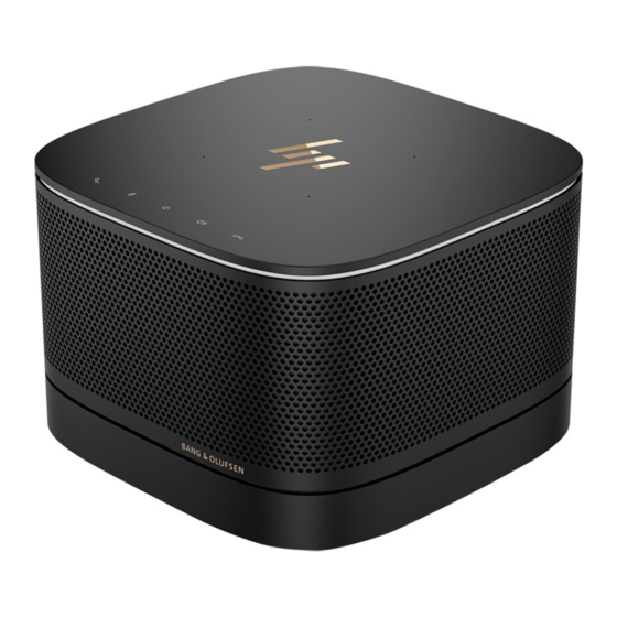
Product features HP Elite Slice for Meeting Rooms G2 features The Elite Slice G2 features Bang & Olufsen audio and wireless communication for Intel Unite or Microsoft Skype Room System (SRS) conferencing software. Four speakers are on the Elite Slice G2, one in each corner and four microphones are on the top. -
Page 8: Top Components
Top components The Elite Slice G2 top components enable call control with capacitive touch buttons for conference calls. Item Component Item Component Answer/Call Volume up Mute Reject/Disconnect call Volume down Rear components Item Component Item Component Power button USB ports (2) Power jack Dual-Mode DisplayPort (D++) port RJ-45 (network) jack... -
Page 9: Side Components
Audio-out (headphone)/Audio-in (microphone) combo jack (disabled from factory, enabled through system BIOS) HP Video Ingest Module The Video Ingest Module is required for the Microsoft SRS. This module enables a video source to be connected to the SRS. The Video Ingest Module does not support Intel Unite software. -
Page 10: Hp Wireless Display Module (Optional)
HP Wireless Display Module (optional) The Elite Slice G2 may be ordered with the optional Wireless Display Module. The wireless receiver transceiver included with the module can be attached to a display. The Wireless Display Module can transmit a signal up to 10 meters to the transceiver in the room. -
Page 11: Hp Optical Disc Drive (Odd) Module (Optional)
HP Optical Disc Drive (ODD) Module (optional) The ODD Module (available as an after-market option) may be ordered to add optical drive functionality. Additional optical drive modules may be connected to an Elite Slice G2 configuration, depending upon the power supply and the total number of powered modules. -
Page 12: Regulatory Information And Serial Number Location
Regulatory information and serial number location Each computer has a unique serial number and a product ID number laser-etched on the base cover of the Elite Slice G2. A copy of these labels is inside the case. Keep these numbers available for use when contacting support for assistance. -
Page 13: Setup
Setup Connecting or removing modules Additional modules may be connected to the Elite Slice G2. Modules should be attached to the base module in the following order, from top to bottom: Video Ingest Module (required for the Microsoft SRS only) ●... -
Page 14: Connecting The Optional Slice Vesa Plate
Align the module connection port on the underside of the Elite Slice G2 with the module expansion connector on the new module and press the computer down firmly. You should hear a quiet click when the modules lock together. The module locks into place and hides the release latch of the module above it. - Page 15 Slide the quick release latch on the back of the VESA Plate to the locked position to lock all modules together. CAUTION: There are four tabs in the VESA Plate. When you position the Elite Slice G2 configuration correctly onto the VESA Plate and slide the quick release latch to the locked position, the four tabs lock the VESA Plate to the Elite Slice G2 assembly.
-
Page 16: Removing Modules
Removing modules CAUTION: Before disconnecting modules, turn off the Elite Slice G2 and disconnect it from any AC power source. Modules cannot be “hot-plugged” or “hot-swapped.” Modules must be removed one at a time, starting at the bottom. Removing the bottom module exposes the release latch of the module above it. -
Page 17: Attaching The Elite Slice G2 To A Mounting Device
NOTE: HP highly recommends that you secure the Elite Slice G2 assembly by attaching a security cable to the rear of the VESA Plate. This stops the quick release latch from being moved to the unlocked position and prevents accidental release of the modules. -
Page 18: Connecting Ac Power
The security cable is designed to act as a deterrent, but it may not prevent the computer from being mishandled or stolen. Connecting AC power The Elite Slice G2 employs the HP Cable and Port Cover to supply power to the elements of the conferencing solution. Connect the Cable and Port Cover to the Elite Slice G2: Pull the port cover down (1) to expose the cable connectors. -
Page 19: Setting Up An Elite Slice G2 Conferencing Solution
Microsoft Skype Room System (SRS) conferencing solution The SRS ships with Microsoft SRS software, HP Elite Slice G2, HP Center of Room Control (CoRC), HP Video Ingest Module, and HP Cable and Port Cover. The HP Wireless Display Module and HP VESA mount are optional. - Page 20 TIP: When routing cables under a table or other surface, cable guides, shown in red above, should be used to minimize stress on the cables. Connect the Video Ingest Module (required) to the Elite Slice G2. Connect additional modules, if desired, to the Elite Slice G2. Place the Elite Slice G2 in a central location.
- Page 21 Insert a rubber plug at the cable exit point (3) to secure the cable. Remove the CoRC back cover from the shipping box (4) and attach it to the back of the CoRC (5). If the Wireless Display Module is installed, perform the following steps to install the wireless receiver transceiver: NOTE: The transceiver must face the front of the Wireless Display Module.
- Page 22 Connect the transceiver to the HDMI port and a powered USB port on the display (3). Alternatively, use the two included screws to mount the transceiver VESA plate (1) onto a wall or table, and then press the transceiver firmly onto the plate (2) until it clicks into place. To remove the transceiver from the VESA plate, slide the release button on the VESA plate.
- Page 23 You may instead connect the display to a powered USB port on the Cable and Port Cover. Connect the display to an HDMI or DisplayPort port on the Cable and Port Cover. (2) NOTE: If dual HDMI ports are required, use a DisplayPort-to-HDMI adapter to add the second HDMI port.
-
Page 24: Intel Unite Conferencing Solution
Follow the Microsoft Skype Room System (SRS) instructions to install the conferencing software on the Elite Slice G2. Intel Unite conferencing solution The Intel Unite conferencing system ships with Intel Unite software, HP Elite Slice G2, and HP Cable and Port Cover. The HP Wireless Display Module and HP VESA mount are optional. Item... - Page 25 Connect the desired modules to the Elite Slice G2. Place the Elite Slice G2 in a central location. Be sure nothing is placed on top of or next to the Elite Slice G2 that could block speakers and microphones. Connect the Cable and Port Cover to the Elite Slice G2: Pull the port cover down (1) to expose the cable connectors.
- Page 26 Connect the wireless receiver transceiver to the HDMI port and a powered USB port on the display (3). TIP: For the best performance, be sure the line of sight between the wireless receiver transceiver and the Wireless Display Module is optimal. To connect a display without the Wireless Display Module, perform the following steps: Connect a display power cord to an AC outlet (1).
- Page 27 You may instead connect the display to a powered USB port on the Cable and Port Cover. Connect the display to an HDMI or DisplayPort port on the Cable and Port Cover. (2) NOTE: If dual HDMI ports are required, use a DisplayPort-to-HDMI adapter to add the second HDMI port.
- Page 28 Press the power button on the Elite Slice G2. Follow the Intel Unite instructions to install the conferencing software on the Elite Slice G2. Chapter 2 Setup...
-
Page 29: Hardware Upgrades
It also provides electrical and mechanical safety information. This guide is located on the web at http://www.hp.com/ergo. IMPORTANT: Static electricity can damage the electrical components of the computer or optional equipment. -
Page 30: Removing And Replacing The Access Panel
Removing and replacing the access panel Removing the access panel The Elite Slice G2 access panel must be removed to access the solid state drive (SSD) and system memory modules. Remove the Elite Slice G2 from any additional modules. For instructions, see Removing modules on page Place the computer upside down on a flat surface covered with a soft cloth to protect the computer from scratches or other damage. -
Page 31: Replacing The Access Panel
Replacing the access panel Place the Elite Slice G2 upside down on a flat surface covered with a soft cloth. Align the access panel with the computer so that the module connection port is clearly visible through the opening in the access panel. Tighten the four captive screws to secure the access panel to the computer. -
Page 32: Upgrading System Memory
SODIMMs constructed with x8 and x16 devices ● NOTE: To avoid compatibility issues, HP recommends that you use only HP memory modules in this computer. The system will not operate properly if you install unsupported DIMM memory. DIMMs constructed with x4 SDRAM are not supported. -
Page 33: Populating Memory Module Slots
Populating memory module slots There are two memory module slots, one slot per channel. The slots are labeled DIMM1 and DIMM3. The DIMM1 slot operates in memory channel B. The DIMM3 slot operates in memory channel A. Item Description System Board Label Slot Color Memory 1 slot, Channel B DIMM1... -
Page 34: Installing System Memory Modules
Installing system memory modules IMPORTANT: You must disconnect the AC power cord and wait approximately 30 seconds for the power to drain before adding or removing memory modules. Regardless of the power-on state, voltage is always supplied to the memory modules as long as the computer is plugged into an active AC outlet. Adding or removing memory modules while voltage is present may cause irreparable damage to the memory modules or system board. - Page 35 Insert the new memory module into the slot at approximately a 30° angle (1), and then press the memory module (2) into the slot so that the latches lock it in place. NOTE: A memory module can be installed in only one way. Match the notch on the module with the tab on the memory module slot.
-
Page 36: Removing And Replacing An Ssd
Removing and replacing an SSD NOTE: Back up the SSD before you remove it so that you can transfer the data to the new SSD. To add an SSD instead of replacing one, purchase a 4-screw after-market option kit to obtain the screws required to mount the drive. - Page 37 Set the new SSD (1) into the cage. Be sure the label side of the SSD is visible. Fasten the four screws (2) to secure the SSD in the cage. Connect the power-and-data cable (1) to the SSD. Set the drive cage (2) in the chassis. Be sure that the SSD connectors are facing the back of the chassis. Align the drive cage tabs with the screw posts in the chassis and fasten the four screws (3) to secure the SSD.
-
Page 38: Appendix A Electrostatic Discharge
● Use a portable field service kit with a folding static-dissipating work mat. ● If you do not have any of the suggested equipment for proper grounding, contact an HP authorized dealer, reseller, or service provider. NOTE: For more information on static electricity, contact an HP authorized dealer, reseller, or service provider. -
Page 39: Appendix B Computer Operating Guidelines, Routine Care And Shipping Preparation
Computer operating guidelines, routine care and shipping preparation Computer operating guidelines and routine care Follow these guidelines to properly set up and care for the computer and monitor: Keep the computer away from excessive moisture, direct sunlight, and extremes of heat and cold. ●... -
Page 40: Shipping Preparation
Shipping preparation Follow these suggestions when preparing to ship the computer: Back up the SSD files to an external storage device. Be sure that the backup media is not exposed to electrical or magnetic impulses while stored or in transit. NOTE: The SSD locks automatically when the system power is turned off. -
Page 41: Appendix C Accessibility
Accessibility HP designs, produces, and markets products and services that can be used by everyone, including people with disabilities, either on a stand-alone basis or with appropriate assistive devices. To access the latest information on HP accessibility, go to http://www.hp.com/accessibility. -
Page 42: Index
Index security cable 11 removing AC power 12 SSD 30 access panel 24 access panel system memory 26, 28 modules 10 removing 24 Intel Unite conferencing 18 SSD 30 replacing 25 Intel Unite, installing 22 replacing accessibility 35 internal components 25 access panel 25 system memory 28 Cable and Port Cover 13, 18... - Page 43 Wireless Display Module 4 wireless receiver transceiver 4 wireless receiver transceiver 4 Index...